manuals.online logo
Brands
  1. Home
  2. •
  3. Brands
  4. •
  5. Staubli
  6. •
  7. Cables And Connectors
  8. •
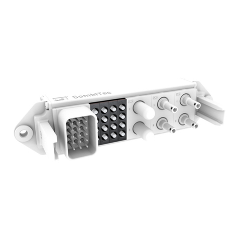
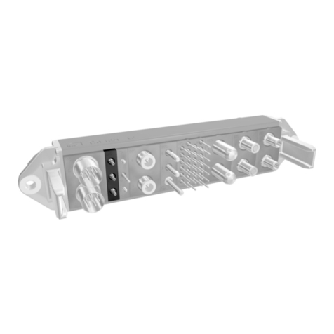
  9. Staubli CombiTac uniq CT-GOF User manual

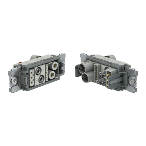
Staubli CombiTac uniq CT-GOF User manual

1 / 4
MA000 (de_en)
Montageanleitung
MA000 (de_en)
Assembly instructions
MA213-06 (es_en)
Instrucciones de montaje
MA213-06 (es_en)
Assembly instructions
CombiTac uniq
cristal de bra óptica CT-GOF
CombiTac uniq
Glass Optical Fibre CT-GOF
Índice
Instrucciones de seguridad ��������������������������������������������������������2
Montaje �������������������������������������������������������������������������������������3
Desmontaje �������������������������������������������������������������������������������4
Capuchones de protección��������������������������������������������������������4
Content
Safety Instructions����������������������������������������������������������������������2
Assembly�����������������������������������������������������������������������������������3
Disassembly ������������������������������������������������������������������������������4
Protective caps ��������������������������������������������������������������������������4
2 / 4
Instrucciones de seguridad Safety instructions
Sólo personal adecuadamente cualicado y especialistas for-
mados podran realizar el montaje y la instalación de los pro-
ductos teniendo en cuenta todas las regulaciones de seguri-
dad aplicables�
Stäubli Electrical Connectors (Stäubli) no se responsabiliza
ante el incumplimiento de estas advertencias�
The products may be assembled and installed exclusively by
suitably qualied and trained specialists duly observing all ap-
plicable safety regulations.
Stäubli Electrical Connectors (Stäubli) does not accept any li-
ability in the event of failure to observe these warnings.
Utilice sólo los componentes y herrmientas indicadas por
Stäubli� No se desvíe de los procedimientos de preparación y
montaje aquí descritos, en caso de una manipulación inade-
cuada no se podrá garantizar la seguridad ni la conformidad
con los datos técnicos. No modique el prodcuto en ningún
caso�
Use only the components and tools specied by Stäubli. In
case of self-assembly, do not deviate from the preparation and
assembly instructions as stated herein, otherwise Stäubli can-
not give any guarantee as to safety or conformity with the
technical data. Do not modify the product in any way.
Los conectores no fabricados por Stäubli que se pueden co-
nectar con elementos Stäubli, a veces denominados por los
fabricantes como „compatibles con Stäubli“ no cumplen con
los requisitos para una conexión eléctrica segura y estable a
largo plazo� No pueden conectarse con elementos Stäubli por
motivos de seguridad� Por tanto, Stäubli no se responsabili-
zará de los daños surgidos por la conexión de conectores no
autorizados por Stäubli con elementos Stäubli�
Connectors not originally manufactured by Stäubli which can
be mated with Stäubli elements and in some cases are even
described as ”Stäubli-compatible” by certain manufacturers
do not conform to the requirements for safe electrical connec-
tion with long-term stability, and for safety reasons must not
be plugged together with Stäubli elements. Stäubli therefore
does not accept any liability for any damages resulting from
mating such connectors (i.e. lacking Stäubli approval) with
Stäubli elements�
Los trabajos aquí descritos no pueden ejecutarse
en piezas conectadas a la red y con tensión.
The work described here must not be carried out
on live or load-carrying parts.
El producto nal debe proporcionar protección al
usuario frente a una descarga eléctrica.
Protection from electric shock must be assured by
the end product (i.e. by the correctly assembled
plug connector) and by its user.
Los conectores no pueden separarse estando car-
gados. Se permite la conexión y desconexión con
tensión.
The plug connections must not be disconnected
under load. Plugging and unplugging when live is
permitted.
Cada vez que el conector sea usado, éste debe ser
inspeccionado previamente por posibles defectos
externos (particularmente en el aislante). Si hay
alguna duda para su seguridad, se debe consultar a
un especialista o el conector debe ser reemplazado.
Each time the connector is used, it should previously
be inspected for external defects (particularly in the
insulation). If there are any doubts as to its safety, a
specialist must be consulted or the connector must
be replaced.
Los conectores en carcasa están protegidos contra
el agua conforme a la clase de protección IP infor-
mada para el producto respectivo.
The plug connectors in the housing are protected
from water in accordance with the IP protection
class stated for the relevant product.
Se deben proteger ante la humedad y suciedad los
conectores no conectados. No se pueden conectar
conectores sucios.
Unmated plug connectors must be protected from
moisture and dirt. The male and female parts must
not be plugged together when soiled.
Encontrará más detalles técnicos en el catálogo del
producto.
For further technical data please see the product
catalogue.
Explicación de los símbolos Explanation of the symbols
Advertencia de voltajes peligrosos Warning of dangerous voltages
Advertencia de área de peligro Warning of a hazard area
Sugerencia o consejo útil Useful hint or tip

3 / 43 / 4
1
2
3
Montaje Assembly
Nota:
El montaje de los contactos de
bra óptica debe realizarse por
personal experto y con el equipo
adecuado. Para crimpar el manguito
de retención, se recomiendan unas
tenazas de crimpado hexagonales y
con un ancho de llave de 3,3mm.
Note:
The assembly of glass bre con-
tacts must be carried out by special-
ised personnel with the appropriate
equipment. For crimping the reten-
tion sleeve, a crimping tool with a
hexagonal form and a wrench size of
3.3mm is recommended.
(ill. 1)
Introducir lateralmente el cable mon-
tado en la placa de sujeción�
Tire del cable hasta que los contactos
se coloquen en la placa de sujeción�
(ill. 1)
Insert assembled cable laterally into
the holding plate�
Pull back cable until contacts are posi-
tioned in the holding plate�
(ill. 2)
Inserte los contactos en el soporte de
contactos con la placa de sujeción
cuidando de que estén correctamente
colocados� (1-4)
(ill. 2)
Push contacts into the contact carrier
with the holding plate.
Make sure that they are correctly
positioned� (1-4)
(ill. 3)
Presione la placa de sujeción hacia el
soporte de contacto hasta que escu-
che cómo las lengüetas de retención
se acoplan�
(ill. 3)
Press holding plate towards the con-
tact carrier until retaining latches have
both engaged audibly�
Atención
Compruebe la posición correcta!
Attention
Check correct position!
4 / 44 / 4
7
4
6
S
8
S
5
Fabricante/Producer:
Stäubli Electrical Connectors AG
Stockbrunnenrain 8
4123 Allschwil/Switzerland
Tel. +41 61 306 55 55
Fax +41 61 306 55 56
mail [email protected]
www.staubli.com/electrical
© by Stäubli Electrical Connectors AG, Switzerland – MA213-06 – 01.2020, Index a, Marketing Communications – Sujeto a modicaciones / Subject to alterations
Desmontaje Disassembly
(ill. 4)
Doble la lengüeta de retención lige-
ramente hacia fuera. En función de
la posición de instalación, puede ser
necesario utilizar un destornillador de
ayuda�
(ill. 4)
Bend the retaining latch slightly out-
wards. Depending on the installation
position, a screwdriver may be used.
(ill. 5)
Desde el lateral de conexión, ejercer
presión en los contactos hasta que la
placa de sujeción salga de la retenci-
ón� Repita la operación con la segun-
da lengüeta de retención�
(ill. 5)
From the plugging side, exert pressure
on the contacts until the holding plate
is pushed out of the retention. Repeat
operation on the second retaining
latch�
(ill. 6)
Saque la placa de sujeción del soporte
de contactos con los contactos� En
caso de contactos de pin se recomi-
enda ejercer presión en los contactos
con un contacto de conexión desmon-
tado� Esto hace que se pueda ejercer
más presión y protege la supercie
extrema de las bras de posibles
daños y suciedad�
(ill. 6)
Pull holding plate out of the contact
carrier with the contacts. When deal-
ing with pin contacts, it is recom-
mended to exert pressure on the
contacts with an unassembled socket
contact� This enables greater pressure
to be exerted and protects the end
surface of the bres from damage and
dirt�
Capuchones de protección Protective caps
Contactos preensamblados con
capuchones de protección (ill. 7-8)
Pre-assembled contacts with pro-
tective caps (ill. 7-8)
Atención
Retirar todos los capucho-nes de
protección (S) antes de conectar�
Attention
Before plugging, remove all the
protective caps (S)�

Other Staubli Cables And Connectors manuals

Staubli MC4-Evo 2 User manual

Staubli

Staubli MC4-Evo 2 User manual

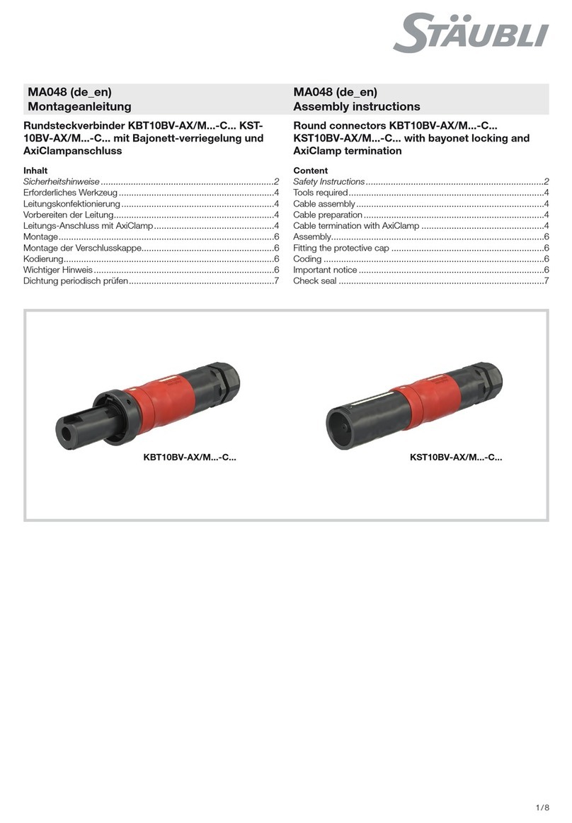
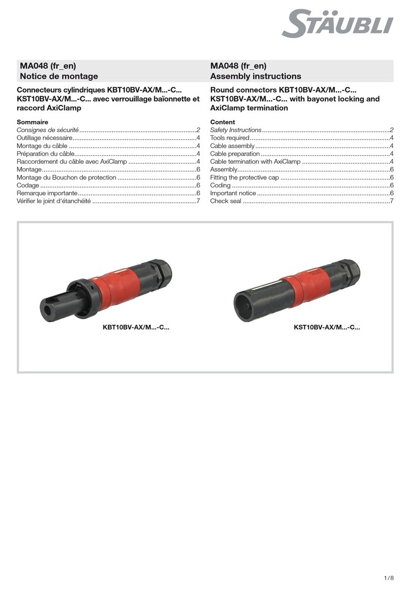
Staubli KST10BV-AX/M C Series User manual

Staubli

Staubli KST10BV-AX/M C Series User manual

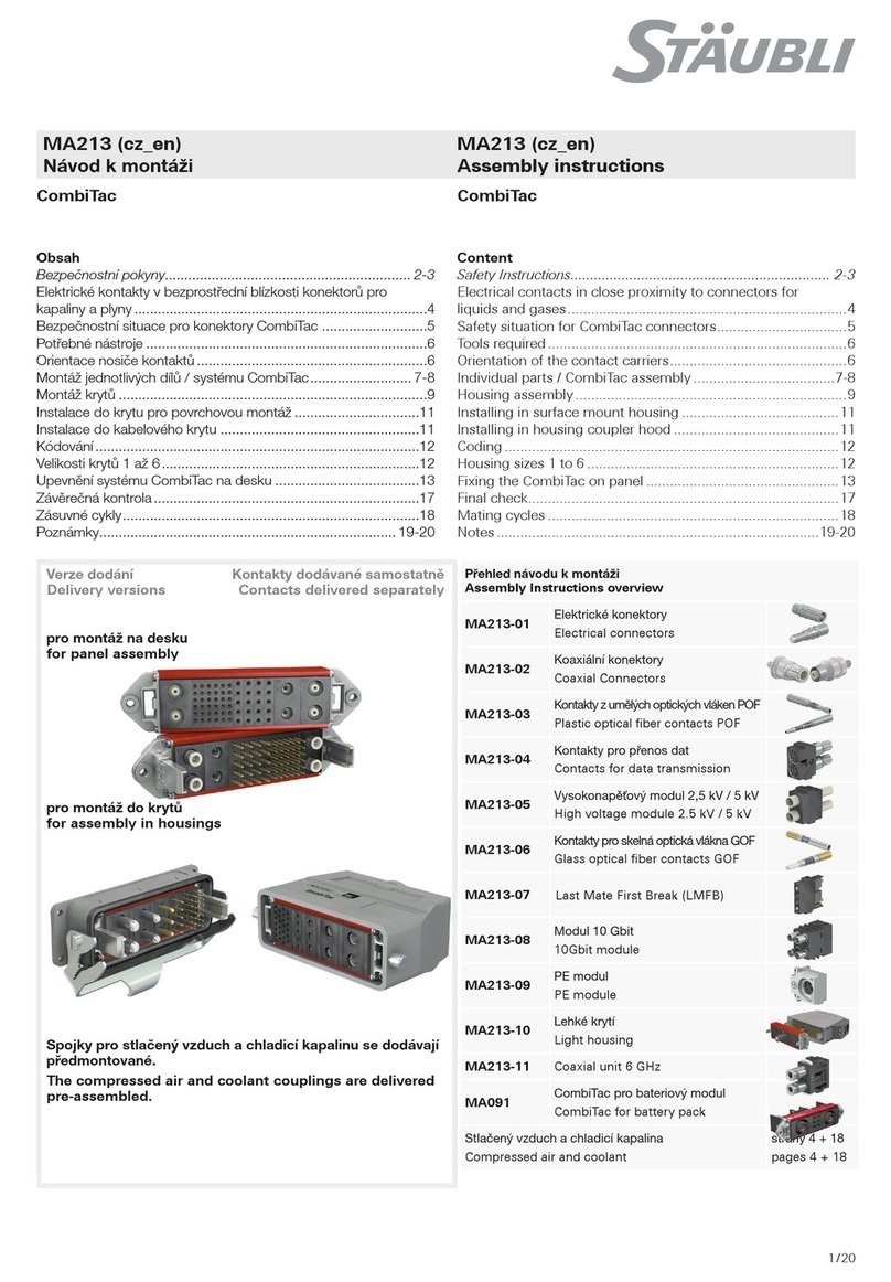
Staubli CombiTac User manual

Staubli

Staubli CombiTac User manual

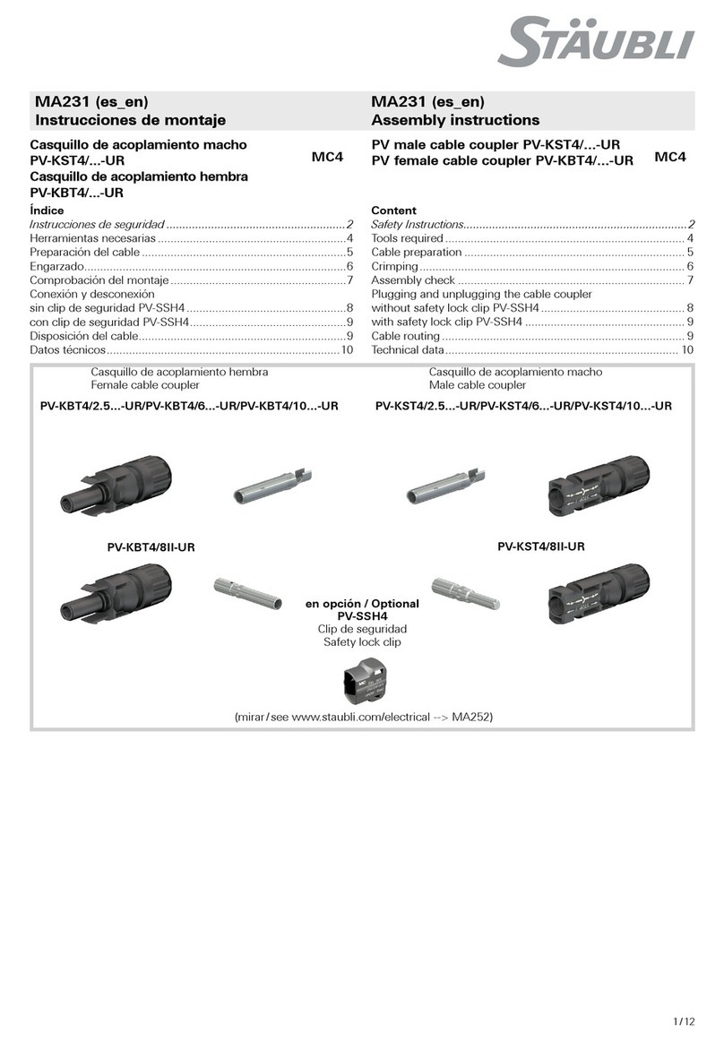
Staubli PV-KST4 UR Series User manual

Staubli

Staubli PV-KST4 UR Series User manual

Staubli PV-KST4 UR Series User manual

Staubli

Staubli PV-KST4 UR Series User manual

Staubli CombiTac uniq CT-GOF User manual

Staubli

Staubli CombiTac uniq CT-GOF User manual

Staubli MC-K PV-ADSP4-S2 Series User manual

Staubli

Staubli MC-K PV-ADSP4-S2 Series User manual

Staubli MC4-Evo 2 User manual

Staubli

Staubli MC4-Evo 2 User manual

Staubli KBT16BV-NS/M Series User manual

Staubli

Staubli KBT16BV-NS/M Series User manual

Staubli MA213-05 User manual

Staubli

Staubli MA213-05 User manual

Staubli CombiTac uniq CT-NET Series User manual

Staubli

Staubli CombiTac uniq CT-NET Series User manual

Staubli PV-KST4 UR Series User manual

Staubli

Staubli PV-KST4 UR Series User manual

Staubli CombiTac direqt User manual

Staubli

Staubli CombiTac direqt User manual

Staubli ID/S21-C Series User manual

Staubli

Staubli ID/S21-C Series User manual

Staubli MC4-Evo 2 User manual

Staubli

Staubli MC4-Evo 2 User manual

Staubli PV-KBT4-EVO 2-UR User manual

Staubli

Staubli PV-KBT4-EVO 2-UR User manual

Staubli MPC-XA User manual

Staubli

Staubli MPC-XA User manual

Staubli CombiTac uniq CT-NET Series User manual

Staubli

Staubli CombiTac uniq CT-NET Series User manual

Staubli PerforMore User manual

Staubli

Staubli PerforMore User manual

Staubli ID/S21-C Series User manual

Staubli

Staubli ID/S21-C Series User manual

Staubli MA231 User manual

Staubli

Staubli MA231 User manual

Staubli CombiTac User manual

Staubli

Staubli CombiTac User manual

Staubli KBT10BV-AX/M C Series User manual

Staubli

Staubli KBT10BV-AX/M C Series User manual

Staubli CombiTac MA213-03 User manual

Staubli

Staubli CombiTac MA213-03 User manual

Popular Cables And Connectors manuals by other brands

HAGOR CPS Pole connector installation manual

HAGOR

HAGOR CPS Pole connector installation manual

RFS RADIAFLEX installation instructions

RFS

RFS RADIAFLEX installation instructions

Elastimold 161LRJS Installation & operating instructions

Elastimold

Elastimold 161LRJS Installation & operating instructions

Rockwell Automation Allen-Bradley Kinetix 2090 Series installation instructions

Rockwell Automation

Rockwell Automation Allen-Bradley Kinetix 2090 Series installation instructions

Extron electronics DVID SL/15 Specifications

Extron electronics

Extron electronics DVID SL/15 Specifications

Philips SWV3502S/10 user manual

Philips

Philips SWV3502S/10 user manual

Stelpro SSFP Series owner's manual

Stelpro

Stelpro SSFP Series owner's manual

CYP CPRO-U8T Operation manual

CYP

CYP CPRO-U8T Operation manual

Lux Tools SW-360 Assembly and operation instruction

Lux Tools

Lux Tools SW-360 Assembly and operation instruction

National Instruments BNC-9920 Operating instructions and specifications

National Instruments

National Instruments BNC-9920 Operating instructions and specifications

Nexans EUROMOLD K800PB/G installation instructions

Nexans

Nexans EUROMOLD K800PB/G installation instructions

Emos P08420 instructions

Emos

Emos P08420 instructions

PTN SUH25E KIT user manual

PTN

PTN SUH25E KIT user manual

Intermatic KPT Series installation guide

Intermatic

Intermatic KPT Series installation guide

HRS ZE064W Series Handling manual

HRS

HRS ZE064W Series Handling manual

Hall Research Technologies ULTRA-V Series user manual

Hall Research Technologies

Hall Research Technologies ULTRA-V Series user manual

Vintage Auto Garage FK Series instructions

Vintage Auto Garage

Vintage Auto Garage FK Series instructions

TÜNKERS SDZ 40 F Installation and operation instructions

TÜNKERS

TÜNKERS SDZ 40 F Installation and operation instructions

manuals.online logo
manuals.online logoBrands
  • About & Mission
  • Contact us
  • Privacy Policy
  • Terms and Conditions

Copyright 2025 Manuals.Online. All Rights Reserved.