Page 5 of 13
23291401 Rev J
®
CABLE CONFIGURATION (Alternate View)
5
7
6
8
3
AUDIO
1AUDIO
2
3
4
1
2
RoHS
COMPLIANT
4
3
2
1
WAKE UP
CTRL
N136
KCC-REI-IM8-SP106-201
Manufactured by ALTINEX
This device complies with part 15 of
the FCC Rules.Operations is subject
to the following two conditions: (1) This device
may not cause harmful interference, and (2)
this device must accept any interference
received, including interference that may cause
undesired operations.
POWER
12V, 6A
SP106-201
MAC:
Default IP: 192.168.1.254
New IP : ______________
SN: 109098115132
11:22:33:44:55:66
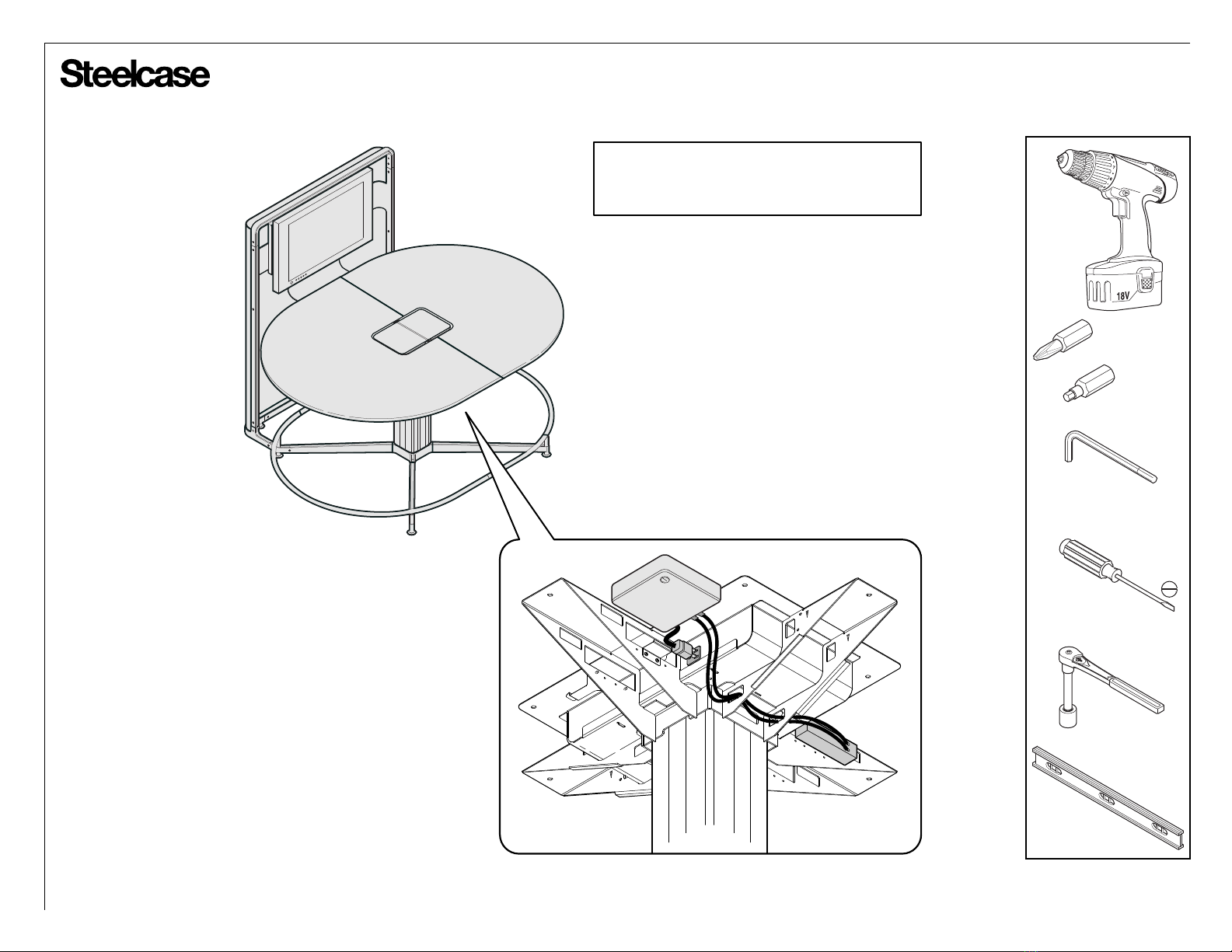
Cooling fan is temperature activated.
Fan operates intermittently.
Maintenance
connection
PUCKs IN
AUX IN
PUCKs IN AUX IN
TO DISPLAY
AUD OUT
NETWORK
1 2
DIGITAL SWITCHER
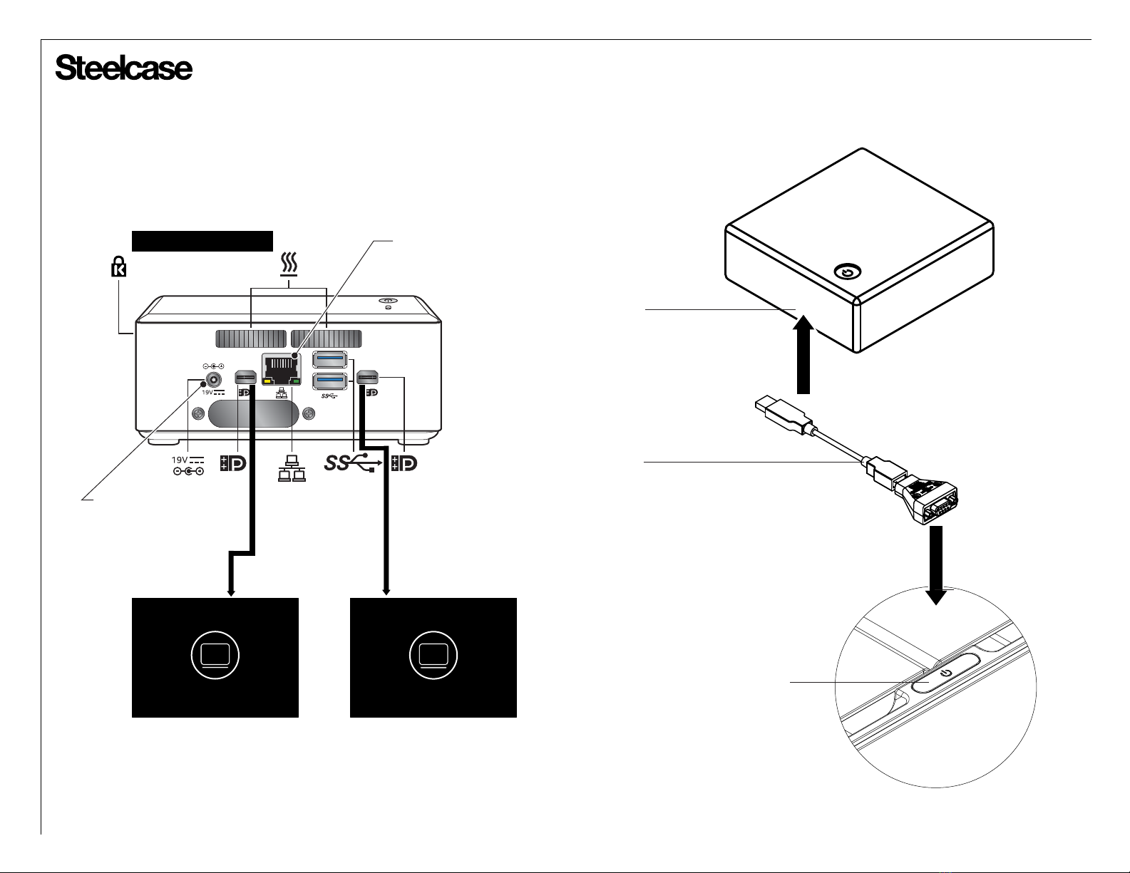
Note:
The HDMI output ports (1 & 2) require specific routing configuration.
Configure: VP Server HDMI output 1 to Switcher Aux input 1,
and VP Server HDMI output 2 to Switcher Aux input 2.
* For one monitor setting, use VP Server HDMI output 1 to
switcher AUX input 1.
Note:
Power cord has a “flag style”
connector. DO NOT confuse
with power supply for switcher.
FLAG STYLE CONNECTOR
STRAIGHT POWER CONNECTOR
VP RECEIVER
Note:
Must connect miniDP to
HDMI cable for each video
output between VP receiver
and Digital Switcher.
Power point plug-in to
available media:scape
outlet.
Plug in ethernet Cable.
1
2