Stihl BT 131 User manual

Contents
1 Guide to Using this Manual.........................2
2 Safety Precautions and Working Techni‐
ques............................................................ 2
3 Assembling the Unit.................................... 7
4 Adjusting the Throttle Cable........................7
5 Fuel............................................................. 7
6 Fueling........................................................ 8
7 Auger Brake................................................ 9
8 Fitting the Auger........................................10
9 Starting / Stopping the Engine.................. 11
10 Operating Instructions...............................13
11 Releasing a Trapped Auger...................... 13
12 Replacing the Air Filter..............................14
13 Adjusting the Carburetor........................... 14
14 Spark Plug................................................ 14
15 Engine Running Behavior......................... 15
16 Lubricating the Gearbox............................15
17 Storing the Machine.................................. 16
18 Maintenance and Care..............................16
19 Main Parts.................................................18
20 Specifications............................................18
21 Maintenance and Repairs......................... 19
22 Disposal.................................................... 19
23 EC Declaration of Conformity................... 20
1 Guide to Using this Manual
1.1 Pictograms
The meanings of the pictograms attached to the
machine are explained in this manual.
Depending on the model concerned, the follow‐
ing pictograms may be attached to your
machine.
Fuel tank; fuel mixture of gasoline
and engine oil
Operate manual fuel pump
Auger brake
1.2 Symbols in text
WARNING
Warning where there is a risk of an accident or
personal injury or serious damage to property.
NOTICE
Caution where there is a risk of damaging the
machine or its individual components.
1.3 Engineering improvements
STIHL's philosophy is to continually improve all
of its products. For this reason we may modify
the design, engineering and appearance of our
products periodically.
Therefore, some changes, modifications and
improvements may not be covered in this man‐
ual.
2 Safety Precautions and
Working Techniques
Special safety precautions must be
observed when working with this
power tool because of its high torque
and the high speed of the auger bit in
certain applications, and because the
auger bits have sharp edges.
It is important you read and under‐
stand the instructions for use before
first use and keep it in a safe place
for future reference. Non-compliance
with the User Manual may cause seri‐
ous or even fatal injury.
Observe all applicable local safety regulations,
e.g. by trade organizations, social insurance
institutions, labor safety authorities etc.
If you have never used a power tool before:
Have your dealer or other experienced user
show you how to operate your machine – or
attend a special course to learn how to operate
it.
Minors are not allowed to work with the power
tool – except adolescents above 16 years of age
who are instructed under supervision.
Children, animals and bystanders must not be
allowed near the machine.
When not using the machine, it must be laid
down in such a way that it does not endanger
anyone. Ensure that the machine cannot be
used without authorization.
English
2 0458-529-8321-B
© ANDREAS STIHL AG & Co. KG 2022
0458-529-8321-B. VA0.D22.
Printed on chlorine-free paper
Printing inks contain vegetable oils, paper can be recycled.
Original Instruction Manual
0000007625_006_GB

The user is responsible for accidents or risks
involving third parties or their property.
Do not lend or rent your power tool without the
User Manual. Be sure that anyone using it under‐
stands the information contained in this manual.
The use of machines that emit noise may be limi‐
ted to certain hours of the day as specified by
national and/or regional or local regulations.
Anyone operating the machine must be well res‐
ted, in good physical health and in good mental
condition.
If you have any condition that might be aggrava‐
ted by strenuous work, check with your doctor
before operating a machine.
If you have a pacemaker: The ignition system of
your machine produces an electromagnetic field
of very low intensity. This field may interfere with
some pacemakers. STIHL recommends that per‐
sons with pacemakers consult their physician
and the pacemaker manufacturer to reduce any
health risk.
Anyone who has consumed alcohol or drugs or
medicines affecting their ability to react must not
operate a power tool.
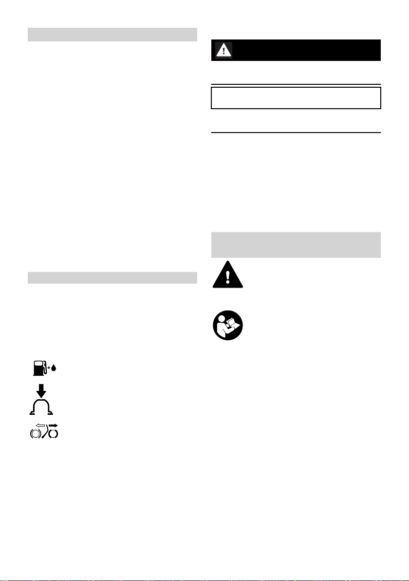
Use your power tool only for drilling holes in soil,
ice and wood – depending on the drilling tool
mounted. Select the drill axis so that the lever of
the drill brake can be supported on the thigh of
the operator at any time during drilling.
It must not be used for any other purposes.
Before drilling, make sure that there are no lines
(e. g. for gas, water, electricity) at the drilling
sites:
–Obtain information from the local utility compa‐
nies
–If in doubt, check the existence of lines with
detectors or test excavations
Only use augers or accessories which have been
approved by STIHL for this machine or which are
technically equivalent. If you have any questions
in this respect, consult your dealer. Use only high
quality parts and accessories. in order to avoid
the risk of accidents and damage to the machine.
STIHL recommends the use of original STIHL
tools and accessories. They are specifically
designed to match the product and meet your
performance requirements.
Never attempt to modify your power tool in any
way since this may increase the risk of personal
injury. STIHL excludes all liability for personal
injury and damage to property caused while
using unauthorized attachments.
Do not use a high-pressure washer to clean the
power tool. The solid jet of water may damage
parts of the unit.
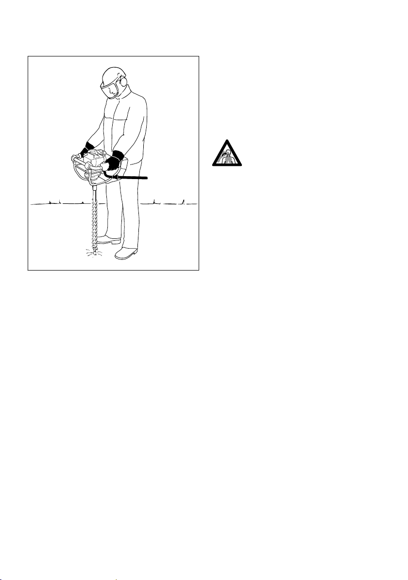
2.1 Clothing and equipment
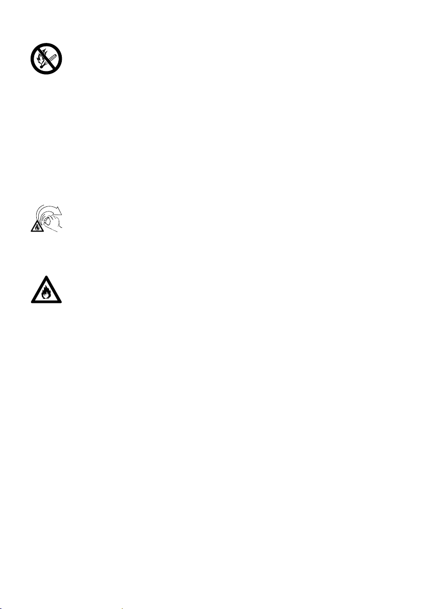
Wear proper protective clothing and equipment.
Clothing must be sturdy but allow
complete freedom of movement.
Wear close-fitting clothes such as a
boiler suit, not a loose jacket.
Do not wear clothing which could become trap‐
ped in wood, brush or moving parts of the
machine. Do not wear a scarf, necktie or jewelry.
Tie up and confine long hair above
your shoulders.
Wear sturdy shoes with non-slip
soles.
WARNING
To reduce the risk of eye injuries,
wear close-fitting safety glasses in
accordance with European Standard
EN 166. Make sure the safety
glasses are a snug fit.
Wear hearing protection, e.g. ear defenders.
Wear a safety hard hat where there is a danger
of head injuries from falling objects.
Wear sturdy protective gloves made
of a resistant material (e. g. leather).
STIHL can supply a comprehensive range of per‐
sonal protective equipment.
2.2 Transporting the machine
Always stop the engine.
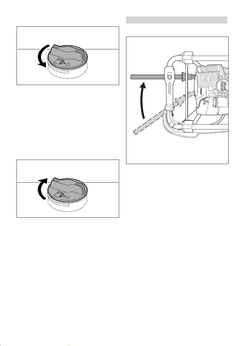
Remove the auger before transporting the power
tool long distances. To reduce the risk of burn
injury, carry the unit by the handle frame with hot
parts of the machine (e.g. gearbox) away from
your body.
By vehicle: When transporting in a vehicle, prop‐
erly secure your machine to prevent turnover,
damage and fuel spillage.
2 Safety Precautions and Working Techniques English
0458-529-8321-B 3

2.3 Refueling
Gasoline is highly flammable – keep
away from fire or flame – do not spill
any fuel – no smoking.
Always shut off the engine before refueling.
Do not fuel a hot engine – fuel may spill and
cause a fire!
Open the fuel cap carefully to allow any pressure
build-up in the tank to release slowly and avoid
fuel spillage.
Only refuel the machine in a well ventilated
place. If fuel has been spilled, immediately clean
the machine – do not allow your clothes to be
splashed with fuel. If that happens, change your
clothes at once.
After fueling, tighten down the screw-
type fuel cap as securely as possible.
This helps reduce the risk of unit vibrations caus‐
ing an incorrectly tightened fuel cap to loosen or
come off and spill quantities of fuel.
Check for fuel leakage! Never start
the engine if fuel has been spilled or
is leaking – Fatal burns may result!
2.4 Before starting
Check that your power tool is properly assem‐
bled and in good condition – refer to appropriate
chapters in the instructions for use.
–Check the fuel system for leaks, especially the
visible parts, e. g., fuel cap, hose connections,
manual fuel pump (only in machines with a
manual fuel pump). In case of leakage and
damage, do not start the engine – risk of fire!
Have the machine serviced by a dealer before
using it
–The stop switch must be easy to push
–Functional drill brake
–Check the choke lever, throttle trigger and
throttle trigger lockout for smooth action -
throttle trigger must return automatically to idle
position. The choke lever must spring back
from the g and < positions to the run posi‐
tion F when the throttle trigger lockout and
throttle trigger are squeezed
–Check that the spark plug boot is secure – a
loose boot may cause arcing that could ignite
combustible fumes and cause a fire!
–Never attempt to modify the controls or safety
devices
–Keep the handles dry and clean – free from oil
and dirt – this is important for safe control of
the machine
To reduce the risk of personal injury, do not
operate your power tool if it is damaged or not
properly assembled!
2.5 Starting the engine
Start the engine at least 3 meters from the fuel‐
ing spot, outdoors only.
Place the power tool on level ground, make sure
you have secure footing.
Engage the drill brake before starting. Otherwise,
the drilling tool may begin to run, causing the
user to lose control of the earth auger.
The machine is operated by a single person only
– do not allow any person to stay within the work‐
ing area – nor with starting.
To reduce the risk of injury, avoid contact with
the drilling tool.
Do not drop-start the engine – start it as descri‐
bed in the instructions for use.
Check idle speed setting: The drilling tool must
not rotate when the engine is idling with the throt‐
tle trigger released.
Keep easily combustible materials (e.g., wood
chips, bark, dry grass, fuel) away from hot
exhaust gases and the hot muffler surface – risk
of fire!
English 2 Safety Precautions and Working Techniques
4 0458-529-8321-B

2.6 Holding and guiding the
machine
9912BA000 KN
Always hold the unit firmly with both hands on
the handles.
Ensure you always have a firm and safe footing –
drill brake on left thigh.
Firmly grasp the handles with the thumbs, left
hand on control handle.
2.7 While working
Make sure you always have good balance and
secure footing.
In the event of impending danger or in an emer‐
gency, switch off the engine immediately by
pressing the stop switch.
Do not allow any other persons in the work area.
Keep well away from other people – risk of acci‐
dents!
Check for correct idling, so that the auger stops
turning when the throttle trigger is released.
Check and correct the idle speed setting at regu‐
lar intervals. If the drilling tool continues to rotate
when the engine is idling, have the machine
checked by your servicing dealer. STIHL recom‐
mends STIHL dealers.
Take special care in slippery conditions – damp‐
ness, snow, ice, on slopes or uneven ground.
Watch out for obstacles: tree stumps, roots – risk
of tripping or stumbling!
Be particularly alert and cautious when wearing
hearing protection because your ability to hear
warnings (shouts, alarms, etc.) is restricted.
Take breaks when you start getting tired or feel‐
ing fatigue – risk of accidents!
Work calmly and carefully – in daylight conditions
and only when visibility is good. Proceed with
caution, do not put others in danger.
As soon as the engine is running, the
power machine generates toxic
exhaust gas. These gases may be
odorless and invisible and may con‐
tain unburned hydrocarbons and ben‐
zene. Never run the engine indoors or
in poorly ventilated locations, even if
your model is equipped with a cata‐
lytic converter.
To reduce the risk of serious or fatal injury from
breathing toxic fumes, ensure proper ventilation
when working in trenches, hollows or other con‐
fined locations. This reduces the risk of serious
or fatal injury from breathing toxic fumes.
Stop work immediately if you start suffering from
nausea, headaches, impaired vision (e.g. your
field of vision gets smaller), impaired hearing,
dizziness, or impaired concentration – these
symptoms may possibly be the result of too-high
exhaust gas concentration – Risk of accidents!
Operate your power tool so that it produces a
minimum of noise and emissions – do not run the
engine unnecessarily, accelerate the engine only
when working.
To reduce the risk of fire, do not smoke while
operating or standing near your power tool. Com‐
bustible fuel vapor may escape from the fuel sys‐
tem.
Dust, fumes and smoke produced while working
may be hazardous to your health. Wear respira‐
tory protection in case of heavy dust or smoke
emission.
If your power tool is subjected to unusually high
loads for which it was not designed (e.g. heavy
impact or a fall), always check that it is in good
condition before continuing work – see also
"Before Starting".
Check in particular that the fuel system has no
leaks and the safety equipment is fully operative.
Never use a power tool that is no longer safe to
operate. In case of doubt, contact a dealer.
2 Safety Precautions and Working Techniques English
0458-529-8321-B 5

Do not operate your power tool in the starting
throttle position – engine speed cannot be con‐
trolled in this position.
To reduce the risk of injury, do not touch the drill‐
ing tool and drilling spindle unless the engine is
stopped and the drilling tool is at a standstill.
Avoid contact with lines carrying elec‐
trical current – Risk of electrical
shock!
Hold the machine firmly so that sudden jolts can
be absorbed – only apply a small amount of
pressure when drilling.
Take particular care when working in
stony areas or ground with roots.
Cover drilled holes and secure them.
To reduce the risk of injury, shut off the engine
and engage the drill brake before changing the
drill.
Do not touch machine parts, particularly the muf‐
fler – Risk of burn injuries.
Always shut off the engine before leaving the
unit unattended.
Check drilling tools at regular short intervals dur‐
ing operation or immediately if there is a noticea‐
ble change in operating behavior. Replace dam‐
aged or dull drilling tools and blades immedi‐
ately.
2.8 Vibrations
Prolonged use of the power tool may result in
vibration-induced circulation problems in the
hands (whitefinger disease).
No general recommendation can be given for the
length of usage because it depends on several
factors.
The period of usage is prolonged by:
–Hand protection (wearing warm gloves)
–Work breaks
The period of usage is shortened by:
–Any personal tendency to suffer from poor cir‐
culation (symptoms: frequently cold fingers,
tingling sensations).
–Low outside temperatures.
–The force with which the handles are held (a
tight grip restricts circulation).
Continual and regular users should monitor
closely the condition of their hands and fingers. If
any of the above symptoms appear (e.g. tingling
sensation in fingers), seek medical advice.
2.9 Maintenance and Repairs
Service the machine regularly. Do not attempt
any maintenance or repair work not described in
the instruction manual. Have all other work per‐
formed by a servicing dealer.
STIHL recommends that you have servicing and
repair work carried out exclusively by an author‐
ized STIHL servicing dealer. STIHL dealers are
regularly given the opportunity to attend training
courses and are supplied with the necessary
technical information.
Only use high-quality replacement parts in order
to avoid the risk of accidents and damage to the
machine. If you have any questions in this
respect, consult a servicing dealer.
STIHL recommends the use of original STIHL
replacement parts. They are specifically
designed to match your model and meet your
performance requirements.
To reduce the risk of injury from unintentional
engine startup, always shut off the engine and
disconnect the spark plug boot before performing
any repairs, maintenance or cleaning work. –
Exception: Carburetor and idle speed adjust‐
ments.
Do not turn the engine over on the starter with
the spark plug boot or spark plug removed since
there is otherwise a risk of fire from uncontained
sparking.
To reduce the risk of fire, do not service or store
your machine near open flames.
Check the fuel filler cap for leaks at regular inter‐
vals.
Use only a spark plug of the type approved by
STIHL and make sure it is in good condition –
see "Specifications".
Inspect the ignition lead (insulation in good con‐
dition, secure connection).
Check the condition of the muffler.
To reduce the risk of fire and damage to hearing,
do not operate your machine if the muffler is
damaged or missing. –
Do not touch a hot muffler since burn injury will
result.
English 2 Safety Precautions and Working Techniques
6 0458-529-8321-B

Vibration behavior is influenced by the condition
of the AV elements – check the AV elements at
regular intervals.
3 Assembling the Unit
3.1 Fitting activating lever for auger
brake
3
2
3
1
9912BA001 KN
► Insert the activating lever (1) into the clamp
► Place the holder (2) onto the activating lever
► Screw in the fastening screws (3) and tighten
3.2 Fit the padding
9912BA002 KN
3
► Hook the padding (1) with the tabs (2) into the
oblong holes in the handle frame
► Fold up the padding
3
9912BA003 KN
► Secure the padding to the handlebar with the
cling strips (3) – do not jam the throttle cable
4 Adjusting the Throttle
Cable
It may be necessary to correct the adjustment of
the throttle cable after assembling the machine
or after a prolonged period of operation.
Adjust the throttle cable only when the machine
is completely and properly assembled.
0000-GXX-2145-A0
► Set the throttle trigger to the full throttle posi‐
tion.
► Rotate the screw in the throttle trigger clock‐
wise until you feel initial resistance. Then
rotate it another half turn in the same direction.
5 Fuel
The engine requires a mixture of gasoline and
engine oil.
WARNING
Avoid direct skin contact with fuel and breathing
in of gasoline fumes.
5.1 STIHL MotoMix
STIHL recommends using STIHL MotoMix. This
pre-blended fuel is free of benzene and lead, is
distinguished by a high octane rating, and
always provides the proper mixing ratio.
3 Assembling the Unit English
0458-529-8321-B 7

STIHL MotoMix uses STIHL HP Ultra two-stroke
engine oil for optimum engine life.
MotoMix is not available in all markets.
5.2 Mixing fuel
NOTICE
Unsuitable fuels or a mixing ratio that deviates
from the specification can lead to severe engine
damage. The engine, seals, fuel lines and fuel
tank may be damaged if low-quality gasoline or
engine oil is used.
5.2.1 Gasoline
Use only high-quality gasoline with an octane rat‐
ing of at least 90 ROC – leaded or unleaded.
Gasoline with an alcohol component exceeding
10% can cause impaired engine performance in
engines with manually adjustable carburetors
and thus should not be used in these engines.
Engines with M-Tronic deliver full engine per‐
formance using gasoline with an alcohol compo‐
nent of up to 27% (E27).
5.2.2 Engine oil
If you mix the fuel yourself, use only STIHL two-
stroke engine oil or another high-performance
engine oil classified as JASO FB, JASO FC,
JASO FD, ISO-L-EGB, ISO-L-EGC or ISO-L-
EGD.
STIHL specifies STIHL HP Ultra two-stroke
engine oil or an equivalent high-performance
engine oil in order to maintain emission limits
over the machine’s service life.
5.2.3 Mixing ratio
with STIHL two-stroke engine oil 1:50; 1:50 =
1 part oil + 50 parts gasoline
5.2.4 Examples
Quantity of gaso‐
line
STIHL two-stroke
engine oil 1:50
Liters Liters (ml)
1 0.02 (20)
5 0.10 (100)
10 0.20 (200)
15 0.30 (300)
20 0.40 (400)
25 0.50 (500)
► Pour oil into an approved safety fuel canister
first, then add gasoline and mix thoroughly
5.3 Storing fuel mixture
Store in approved safety fuel canisters only in a
dry, cool and secure place protected against light
and sunlight.
Fuel mixture deteriorates with age – mix only as
much as needed for a few weeks. Do not store
fuel mixture for longer than 30 days. The fuel
mixture can become unusable more quickly if
exposed to light, sunlight or low or high tempera‐
tures.
STIHL MotoMix however can be stored for up to
5 years without any problems.
► Shake the canister containing the fuel mixture
thoroughly before refueling
WARNING
Pressure may have built up in the canister –
open it carefully.
► The fuel tank and the canister in which fuel
mixture is stored should be cleaned thoroughly
from time to time
Residual fuel and the liquid used for cleaning
must be disposed of in accordance with regula‐
tions and without harming the environment!
6 Fueling
6.1 Preparations
0000-GXX-0476-A0
► Before fueling, clean the filler cap and the area
around it to ensure that no dirt falls into the
tank.
► Position the machine so that the tank cap
faces up.
English 6 Fueling
8 0458-529-8321-B

6.2 Opening the Tank Cap
002BA447 KN
► Turn the cap counterclockwise until it can be
removed from the tank opening.
► Remove the tank cap.
6.3 Filling Up with Fuel
Take care not to spill fuel while fueling and do
not overfill the tank.
STIHL recommends you use the STIHL filler noz‐
zle for fuel (special accessory).
► Fill up with fuel.
6.4 Closing the Tank Cap
002BA448 KN
► Place the cap in the opening.
► Turn the cap clockwise as far as stop and
tighten it down as firmly as possible by hand.
7 Auger Brake
7.1 Engaging the Auger Brake
0000-GXX-1860-A0
A
► Move the activating lever to position A .
–when starting
–at idling speed
–to unwind a trapped auger
If the auger snags on an obstacle in the hole
(e.g. roots or stones) the machine will begin to
turn counterclockwise – the activating lever is
pressed against the operator's thigh and thus
engages the auger brake.
7 Auger Brake English
0458-529-8321-B 9

7.2 Disengaging the Auger Brake
0000-GXX-1861-A0
B
► Move the activating lever to position B
7.3 Checking Operation of Auger
Brake
The auger brake is subject to normal wear and
tear. Regularly check that it is operating properly
before you start work and after releasing a trap‐
ped auger.
7.3.1 Before starting work and after releas‐
ing a trapped auger
► With the engine running at idle speed, engage
the auger brake and then open the throttle
wide for no more than 3 seconds – the auger
must not rotate.
If the auger brake fails, have it repaired immedi‐
ately by your dealer – STIHL recommends that
this work be performed by a STIHL servicing
dealer.
8 Fitting the Auger
► Shut off the engine and engage the auger
brake – see "Auger Brake".
► Put the machine down.
9912BA010 KN
1
2
3
3
► Pull the retaining pin (1) out of the auger's
shank.
► Push the auger (2) onto the drilling spindle so
that the holes (3) line up.
► Push the retaining pin into the hole.
► Spring clip on the retaining pin must fit snugly
around the auger's shank.
English 8 Fitting the Auger
10 0458-529-8321-B

9 Starting / Stopping the
Engine
9.1 Engaging the Auger Brake
0000-GXX-1860-A0
A
► Move the activating lever to position A . Auger
brake is engaged and auger is blocked.
9.2 Controls
2
1
3
0000-GXX-0477-A0
1 Throttle trigger lockout
2 Throttle trigger
3 Stop switch with Run and Stop positions.
Depress the stop switch (…) to switch off the
ignition – see "Function of Stop Switch and
Ignition System".
9.2.1 Function of Stop Switch and Ignition
System
The stop switch is normally in the Run position,
i.e. when it is not depressed: The ignition is
switched on – the engine is ready to start. Oper‐
ate the stop switch to switch off the ignition. The
ignition is switched on again automatically after
the engine stops.
9.3 Starting the Engine
0000-GXX-0478-A0
► Press the manual fuel pump bulb (9) at least
five times – even if the bulb is already filled
with fuel.
► Press home the choke knob (8) and turn it to
the required position – it must engage
gif the engine is cold
<for warm start – also use this position if the
engine has been running but is still cold.
9 Starting / Stopping the Engine English
0458-529-8321-B 11

9.4 Cranking
0000-GXX-1862-A0
► Place the unit on the ground:
► Check that the auger brake is engaged.
► Make sure you have a safe and secure foot‐
ing.
► Put your left foot on the handle frame.
► Left hand on the handle frame – do not touch
the throttle trigger or lockout lever – your
thumb should be under the fan housing.
► Hold the starter grip with your right hand.
► Pull the starter grip slowly until you feel it
engage and then give it a brisk strong pull.
NOTICE
Do not pull out the starter rope all the way – it
might otherwise break.
► Do not let the starter grip snap back. Guide it
slowly back into the housing so that the starter
rope can rewind properly.
► Continue cranking until the engine runs.
9.4.1 As Soon As the Engine Runs
0000-GXX-1558-A0
► Depress throttle trigger lockout and immedi‐
ately blip the throttle trigger – the choke knob
moves to the run F position.
NOTICE
Since the auger brake is still engaged, the
engine must be returned to idling speed immedi‐
ately – or the clutch might otherwise be dam‐
aged.
0000-GXX-1861-A0
B
► Stand the machine on the tip of the auger.
► Disengage the auger brake by moving the
activating lever to position B. Your earth auger
is now ready for operation.
English 9 Starting / Stopping the Engine
12 0458-529-8321-B

WARNING
Make sure the carburetor is correctly adjusted.
The auger must not rotate when the engine is
idling.
Your machine is now ready for operation.
9.5 Stopping the Engine
► Depress the momentary contact stop switch –
the engine stops – release the stop switch – it
springs back to the run position.
9.6 Other Hints on Starting
Engine stalls in cold start position g or under
acceleration.
►Move the choke knob to < and continue
cranking until the engine runs.
Engine does not start in warm start position <
►Move the choke knob to g and continue
cranking until the engine runs.
If the engine does not start
► Check that all settings are correct.
► Check that there is fuel in the tank and refuel if
necessary.
► Check that the spark plug boot is properly con‐
nected.
► Repeat the starting procedure.
Engine is flooded
►Move the choke knob to F and continue crank‐
ing until the engine runs.
Fuel tank run until completely dry
► After refueling, depress the manual fuel pump
bulb at least 5 times – even if the bulb is
already filled with fuel.
► Set the choke knob to suit the engine temper‐
ature.
► Now start the engine.
10 Operating Instructions
10.1 During Break-In Period
A factory-new machine should not be run at high
revs (full throttle off load) for the first three tank
fillings. This avoids unnecessary high loads dur‐
ing the break-in period. As all moving parts have
to bed in during the break-in period, the frictional
resistances in the engine are greater during this
period. The engine develops its maximum power
after about 5 to 15 tank fillings.
10.2 During Operation
After a long period of full throttle operation, allow
the engine to run for a short while at idle speed
so that engine heat can be dissipated by the flow
of cooling air. This helps protect engine-mounted
components (ignition, carburetor) from thermal
overload.
10.3 After Finishing Work
Storing for a short period: Wait for the engine to
cool down. To avoid condensation, fill the fuel
tank and keep the machine in a dry place, well
away from sources of ignition, until you need it
again. For longer out-of-service periods – see
"Storing the Machine".
10.4 Working with shaft extension
(special accessory)
Do not fit the shaft extension until the full length
of the auger is in the hole.
WARNING
Starting a hole with the shaft extension fitted
increases the risk of personal injury because the
unit is then at chest height and cannot be con‐
trolled properly. For the same reason the shaft
extension must be removed before the full length
of the auger is pulled out of the hole.
11 Releasing a Trapped
Auger
11.1 If the auger jams in the drill
hole
► Shut off the engine immediately.
► Depress the momentary contact stop switch –
the engine stops – release the stop switch – it
springs back to the run position.
10 Operating Instructions English
0458-529-8321-B 13

0000-GXX-1860-A0
A
► Engage the auger brake by moving the acti‐
vating lever to position A.
► Rotate the whole machine counterclockwise to
unwind the auger from the ground.
► After releasing the trapped auger, check oper‐
ation of the auger brake – see “Auger Brake”.
12 Replacing the Air Filter
Filters have an average life of more than a year.
Do not remove the filter cover or replace the air
filter as long as there is no noticeable loss of
power.
12.1 If there is a noticeable loss of
engine power.
► Remove padding from the handle frame.
1
1
0000-GXX-0482-A0
2
3
4
►Turn the choke knob to g.
► Take out the screws (1).
► Remove the filter cover (2).
► Clean away loose dirt from around the filter.
► Remove the filter element (3).
► Replace dirty or damaged filter.
► Replace any damaged parts.
12.2 Installing the Filter Element
► Install the filter element in the filter housing
and fit the cover.
► Fit the screws and tighten them down firmly.
► Fit the padding – see "Assembling the Unit".
13 Adjusting the Carburetor
The carburetor has been set at the factory to pro‐
vide an optimum fuel-air mixture under most
operating conditions.
13.1 Adjusting Idle Speed
0000-GXX-0495-A0
Engine stops while idling
► Warm up the engine for about 3 minutes.
► Turn the idle speed screw (LA) slowly clock‐
wise until the engine runs smoothly – the
auger must not rotate.
Auger rotates when engine is idling
► Turn the idle speed screw (LA) slowly counter‐
clockwise until the auger stops rotating and
then turn the screw about another 1/2 to 3/4
turn in the same direction.
WARNING
If the auger continues to rotate when the engine
is idling, have your machine checked and
repaired by your servicing dealer.
14 Spark Plug
► If the engine is down on power, difficult to start
or runs poorly at idle speed, first check the
spark plug.
► Fit a new spark plug after about 100 operating
hours – or sooner if the electrodes are badly
eroded. Install only suppressed spark plugs of
the type approved by STIHL – see "Specifica‐
tions".
English 12 Replacing the Air Filter
14 0458-529-8321-B

14.1 Removing the Spark Plug
3
2
1
0000-GXX 0537-A0
► Remove the cover (1).
► Pull off the spark plug boot (2).
► Unscrew the spark plug (3).
14.2 Checking the Spark Plug
000BA039 KN
A
► Clean dirty spark plug.
► Check electrode gap (A) and readjust if neces‐
sary – see "Specifications".
► Rectify the problems which have caused foul‐
ing of the spark plug.
Possible causes are:
–Too much oil in fuel mix.
–Dirty air filter.
–Unfavorable running conditions.
1
000BA045 KN
WARNING
Arcing may occur if the adapter nut (1) is loose
or missing. Working in an easily combustible or
explosive atmosphere may cause a fire or an
explosion. This can result result in serious inju‐
ries or damage to property.
► Use resistor type spark plugs with a properly
tightened adapter nut.
14.3 Installing the Spark Plug
► Screw the spark plug (3) into the cylinder.
► Tighten down the spark plug (3) with the com‐
bination wrench.
► Press the boot (2) firmly onto the spark plug.
► Fit the cover (1) and screw it down firmly.
15 Engine Running Behavior
If engine running behavior is still unsatisfactory
after the air filter has been serviced and the car‐
buretor and throttle cable have been adjusted
correctly, the cause may also be in the muffler.
Have the muffler checked for contamination (cok‐
ing) by a servicing dealer!
STIHL recommends that maintenance and repair
work be carried out only by authorized STIHL
dealers.
16 Lubricating the Gearbox
Check grease level after every 50 hours of oper‐
ation and re-lubricate if necessary.
1
9912BA019 KN
► Remove the screw plug (1).
15 Engine Running Behavior English
0458-529-8321-B 15

9912BA020 KN
► If no grease can be seen on the inside of the
screw plug (1): Screw the tube (2) of STIHL
gear lubricant (special accessory) into the filler
hole.
► Squeeze about 5 ‑ 10 g (1/5 ‑ 2/5 oz) grease
into the gearbox.
NOTICE
Do not completely fill the gearbox with grease.
► Unscrew the tube (2).
► Insert the screw plug (1) and tighten it down
firmly.
17 Storing the Machine
If not used for periods of about 30 days or longer
► Remove the drilling tool
► Drain and clean the fuel tank in a well-ventila‐
ted area.
► Dispose of fuel properly in accordance with
local environmental requirements.
► If a manual fuel pump is fitted: Press the man‐
ual fuel pump at least 5 times.
► Start the engine and run it at idling speed until
it stops
► Thoroughly clean the machine
► Store the machine in a dry and secure loca‐
tion. Keep out of the reach of children and
other unauthorized persons
18 Maintenance and Care
The following intervals apply for normal operating
conditions. The specified intervals must be short‐
ened accordingly when working for longer than nor‐
mal or under difficult cutting conditions (extensive
dust, etc.).
Before starting work
At the end of work and/or daily
Whenever tank is refilled
Weekly
Monthly
Annually
If faulty
If damaged
As required
Complete machine Visual inspection (condi‐
tion, leaks)
X X
Clean X
Replace any damaged
parts
X X
Drill brake Function test X X
have them serviced by a
specialist dealer1)
X
Control handle Function test X X
Air filter Visual examination X X
Replace2) X X
Manual fuel pump (if
present)
check X
Have repaired by a spe‐
cialist dealer1)
X
Fuel pickup body in fuel
tank
Have checked by
dealer1)
X
English 17 Storing the Machine
16 0458-529-8321-B

The following intervals apply for normal operating
conditions. The specified intervals must be short‐
ened accordingly when working for longer than nor‐
mal or under difficult cutting conditions (extensive
dust, etc.).
Before starting work
At the end of work and/or daily
Whenever tank is refilled
Weekly
Monthly
Annually
If faulty
If damaged
As required
Have replaced by serv‐
icing dealer1)
X X X
Fuel tank Clean X X
Carburetor Check idle adjustment –
drilling spindle must not
rotate
X X
Adjust idle speed X
Spark plug Set electrode gap X
Replace after every 100
hours of operation
Cooling air intakes Visual examination X
Clean X
Cylinder fins Have cleaned by
dealer1)
X
Valve clearance If power is low or crank‐
ing effort very high, have
valve clearance checked
and, if necessary, adjus‐
ted by dealer1)
X
Combustion chamber Have cleaned after
every 150 hours of oper‐
ation by dealer1)
X
Spark arresting screen in
muffler,
available in market-spe‐
cific versions
check X X
Clean or replace X X
All accessible screws,
nuts and bolts (not
adjusting screws)
Tighten X
Anti-vibration elements check X X X
Have replaced by serv‐
icing dealer1)
X
Gearbox lubrication check X
top up X
Drilling spindle Clean X
Drilling tool check X
replace X X
Auger blade check X
Turn over or replace X X
Safety information label replace X
18 Maintenance and Care English
0458-529-8321-B 17

The following intervals apply for normal operating
conditions. The specified intervals must be short‐
ened accordingly when working for longer than nor‐
mal or under difficult cutting conditions (extensive
dust, etc.).
Before starting work
At the end of work and/or daily
Whenever tank is refilled
Weekly
Monthly
Annually
If faulty
If damaged
As required
1)STIHL recommends STIHL dealers
2)Only if there is a noticeable loss of engine power
19 Main Parts
0000-GXX-1863-A0
10
7
8
9
11
15
12
#
1
5
23
4
6
14
13
1 Stop switch
2 Throttle trigger lockout
3 Starter grip
4 Filter cover
5 Carburetor adjusting screw
6 Tank cap
7 Screw plug
8Muffler with spark arresting screen1)
9 Drilling spindle
10 Hip padding
11 Choke knob
12 Manual fuel pump
13 Spark plug cover
14 Throttle trigger
15 Auger brake lever
# Serial Number
20 Specifications
20.1 Engine
STIHL single cylinder four-stroke engine with
mixture lubrication
Displacement: 36.3cm3
Cylinder bore: 43 mm
Piston stroke: 25 mm
Engine power to ISO 8893: 1.4 kW (1.9 hp) at
8500 1/min
Idle speed: 2800 rpm
Cut-off speed: 9500 rpm
Valve clearance
Inlet valve: 0.10 mm
Exhaust valve: 0.10 mm
20.2 Ignition system
Electronic magneto ignition
Spark plug (suppressed): NGK CMR 6H,
BOSCH USR 4AC
Electrode gap: 0.5 mm
20.3 Fuel system
All-position diaphragm carburetor with integral
fuel pump
Fuel tank capacity: 710 cm3 (0.71 l)
1) Spark arresting screen not fitted on all markets
English 19 Main Parts
18 0458-529-8321-B

20.4 Drilling gear
2-level spur gearbox
Transmission ratio: 47.5:1
Max. spindle speed: 200 rpm
Max. torque at drilling spindle: 81 Nm
Lubrication: STIHL gear lubri‐
cant for brushcut‐
ters
20.5 Weight
without fuel, without drilling
tool:
10 kg
20.6 Dimensions
Length with support frame: 400 mm
Width with support frame: 530 mm
Height without drilling tool: 365 mm
20.7 Sound and Vibration Levels
When determining sound and vibration levels,
idling and the nominal maximum engine speed
are taken into account in a ratio of 1:4.
For further details on compliance with Vibration
Directive 2002/44/EC, see
www.stihl.com/vib
20.7.1 Sound pressure level Lpeq in accord‐
ance with ISO 11201
92 dB(A)
20.7.2 Sound power level Lweq in accordance
with ISO 3744
100 dB(A)
20.7.3 Vibration level ahv,eq in accordance
with ISO 20643
90 mm earth auger
Handle, left: 1.7 m/s2
Handle, right: 2.0 m/s2
The K‑factor in accordance with Directive
2006/42/EC is 2.0 dB(A) for the sound pressure
level and sound power level; the K‑factor in
accordance with Directive 2006/42/EC is
2.0 m/s2 for the vibration level.
20.8 REACH
REACH is an EC regulation and stands for the
Registration, Evaluation, Authorization and
Restriction of Chemical substances.
For information on compliance with the REACH
regulation (EC) No. 1907/2006 see
www.stihl.com/reach
20.9 Exhaust Emissions
The CO2 value measured in the EU type appro‐
val procedure is specified at
www.stihl.com/co2
in the product-specific technical data.
The measured CO2 value was determined on a
representative engine in accordance with a
standardized test procedure under laboratory
conditions and does not represent either an
explicit or implied guarantee of the performance
of a specific engine.
The applicable exhaust emission requirements
are fulfilled by the intended usage and mainte‐
nance described in this User Manual. The oper‐
ating license shall be void if the engine is modi‐
fied in any way.
21 Maintenance and Repairs
Users of this machine may only carry out the
maintenance and service work described in this
user manual. All other repairs must be carried
out by a servicing dealer.
STIHL recommends that you have servicing and
repair work carried out exclusively by an author‐
ized STIHL servicing dealer. STIHL dealers are
regularly given the opportunity to attend training
courses and are supplied with the necessary
technical information.
When repairing the machine, only use replace‐
ment parts which have been approved by STIHL
for this power tool or are technically identical.
Only use high-quality replacement parts in order
to avoid the risk of accidents and damage to the
machine.
STIHL recommends the use of original STIHL
replacement parts.
Original STIHL parts can be identified by the
STIHL part number, the { logo and the
STIHL parts symbol K (the symbol may appear
alone on small parts).
22 Disposal
Contact the local authorities or your STIHL serv‐
icing dealer for information on disposal.
Improper disposal can be harmful to health and
pollute the environment.
21 Maintenance and Repairs English
0458-529-8321-B 19

000BA073 KN
► Take STIHL products including packaging to a
suitable collection point for recycling in accord‐
ance with local regulations.
► Do not dispose with domestic waste.
23 EC Declaration of Con‐
formity
ANDREAS STIHL AG & Co. KG
Badstr. 115
D-71336 Waiblingen
Germany
declare under our sole responsibility that
Designation: Earth auger
Make: STIHL
Series: BT 131
Serial identification num‐
ber:
4313
Displacement: 36.3 cm3
conforms to the relevant provisions of Directives
2011/65/EU, 2006/42/EC and 2014/30/EU and
has been developed and manufactured in com‐
pliance with the following standards in the ver‐
sions valid on the date of production:
EN ISO 12100, EN 55012, EN 61000‑6‑1
Technical documents deposited at:
ANDREAS STIHL AG & Co. KG
Produktzulassung
The year of manufacture and serial number are
applied to the product.
Done at Waiblingen, 15.07.2021
ANDREAS STIHL AG & Co. KG
pp
Dr. Jürgen Hoffmann
Director Product Certification & Regulatory
Affairs
English 23 EC Declaration of Conformity
20 0458-529-8321-B
Other manuals for BT 131
4
Table of contents
Other Stihl Lawn And Garden Equipment manuals

Stihl
Stihl MM 56 User manual

Stihl
Stihl FixCut 30-2 User manual

Stihl
Stihl BF-MM User manual

Stihl
Stihl HSA 26 User manual

Stihl
Stihl FCB-KM User manual

Stihl
Stihl HS 82 User manual

Stihl
Stihl KombiTool KombiSystem SP-KM User manual

Stihl
Stihl RLA 240 User manual

Stihl
Stihl FCB-KM User manual

Stihl
Stihl KW 85 User manual