Still FM-X-20 Manual

1
OPERATION, MAINTENANCE AND
SERVICE HANDBOOK
STILL FM-X20
SERIAL NUMBER : TR190005
GROUP CATEGORY : II 2G T4
PROTECTION : Ex db, ib, eb IIB Gb

2
EU DECLARATION CONFORMITY
TYPE : STILL FM-X20
SERIAL NUMBER / YEAR : TR190005 / 2019
ORIGINAL CHASSIS NUMBER : 511904F00059
MARKING SUPPLEMENTARY : II 2G T4
PROTECTION : Ex db, ib, eb IIB Gb
Company certify that the material specified above is in
conformity with the requirements of the EUROPEAN ATEX directive
2014/34/EU for the use of this material in hazardous atmosphere and in
accordance with CENELEC standards:
Notification d’assurance qualité ATEX /Quality assurance notification:N°ITS16ATEXQ01544
Adresse / Address: IntertekT House , Cleeve Road , Leadherhead, Surrey, KT22 7SB
Numéro de l’organisme Number : 0359
EN 60079-0:2012, EN 60079-1:2014, EN60079-7:2015,
EN 60079-11 :2012, EN 1755, EN 80079-36:2016
Hakan CALISKAN
President and CEO
Vigneux sur Seine,the APRIL 10th, 2019
Accessories and system of safety for a use into
Explosive Atmosphere Directive ATEX 2014/34/EU

3
CONTENTS
1. GENERAL INFORMATION..................................................................................................................... 4
1.1 THE PURPOSE OF MANUAL ........................................................................................................... 4
1.2 GENERAL SAFETY WARNINGS........................................................................................................ 4
1.3 INFORMATION ABOUT ATEX DIRECTIVE AND REGULATION......................................................... 5
1.4 ASSESSMENT of EXPLOSION RISKS ................................................................................................ 7
1.5 MANUFACTURER'S RESPONSIBILITY............................................................................................ 16
1.6 USER’S RESPONSIBILITY............................................................................................................... 16
2. USAGE................................................................................................................................................ 16
2.1 PRE-START CHECK........................................................................................................................ 16
2.2 START........................................................................................................................................... 16
2.3 STOPPING .................................................................................................................................... 16
3. ELECTRICAL AND NON-ELECTRICAL EX EQUIPMENT......................................................................... 17
3.1 ELECTRICAL EQUIPMENTS ........................................................................................................... 18
3.2 NON-ELECTRICAL EQUIPMENTS .................................................................................................. 24
4. PERIODICAL MAINTENANCE AND PROTECTION OF PARTS ............................................................... 24
5. CHECKS .............................................................................................................................................. 24
6. REPAIR AND SERVICE......................................................................................................................... 25
6.1 POSSIBLE TROUBLES: TROUBLESHOOTING ................................................................................. 25
6.2 TECHNICAL SUPPORT REQUEST................................................................................................... 26
6.3 WARRANTY CONDITIONS ............................................................................................................ 26
6.4 IMPORTANT................................................................................................................................. 26
7.COMUNICATION................................................................................................................................. 27
8. TORQUE SETTING .............................................................................................................................. 28

4
1. GENERAL INFORMATION
1.1 THE PURPOSE OF MANUAL
This manual includes basic instructions, service, maintenance and directions about activating,
stopping, emergency stopping of machine (STILL FM-X20) that is completed its Atex
Compliance process within the scope of Regulation on the Equipment and Protective Systems
Intended For Use In Potentially Explosive Atmospheres (2014/34/EU), 30.06.2016 date and
29758 number.
The use of equipment in hazardous atmosphere or in hazardous areas such as petroleum
industries, chemical industries, refineries, fuel depots, aerosol storage solvent requires the use of
safety equipment. Dusty environments are also subject to special provisions and precautions
based on the presence of conductive dust, non-conductive, volatile.
Different standards guide the user to choose the type of material to be adopted. Electrical
equipment should be in accordance with European standards CENELEC.
Several types of protection are available and used to protect electrical and electronic components
following:
- Categories of risk areas according to the European Directive 2014/34/EU
- Type of industries,
- Nature of the atmosphere.
The AIRMEEX Company offers corresponding sets of protections.
The truck STILL FM-X20 has mainly been modified in accordance with the essential
requirements of the ATEX Directive 2014/34/EU and CENELEC standards:
-EN1755:2015 Handling lift-truck equipment
-EN60079-0:2012 General specifications in Gas atmosphere
-EN60079-1:2014 Explosion proof shell protection ‘d’
-EN60079-7:2015 Equipment protection by increased safety “e”
-EN60079-11:2012 Equipment protection by intrinsic safety "i"
1.2 GENERAL SAFETY WARNINGS
There are general terms about that the user should pay attention for continuation Atex
Compliance of the machine.
Airmeex Industry explains type, lot or serial number, other useful information to identify the
product and explosive atmosphere group category definitions of every equipment and system that
we have done as a producer on the product label.
The user have to pay attention to safety warnings on the ex equipment product label.

5
Ex equipment that is on the system should not be opened in explosive atmospheres and areas
where there is risk of explosive atmosphere.
Every intervention that will make to protect Ex compliance continuity of equipment must be
under Airmeex’s responsibility. Because of possible interventions that will make on the ex
equipment or machine out of Airmeex Knowledge, the product is examined as out of warranty. It
causes the lost of machine’s Atex compliance.
To summarize briefly;
- Keep this technical manual with the original technical manual.
- Carefully read these instructions before any use of this pallet truck.
- Do not modify this truck without permission of AIRMEEX Company.
- The truck must be operated and maintained as originally intended by the manufacturer.
- The operation, use, review, maintenance and repairs must be performed according to
conventional rules.
- All the accessories installed on the pallet truck shall be preserved. Avoid excessive dust
accumulation.
- Any abnormality detected on the pallet truck, and any maintenance, must be indicated on the
machine register.
This manual identifies the ATEX components manufactured and installed by the AIRMEEX
Company.
The driving position and control devices are standard, the safety and use are identical to those of
a conventional vehicle. It should follow the safety rules described in the manufacturer's manual.
If the machine goes into default through AIRMEEX equipment, turn off the machine and alert a
competent person to check the system and determine the reason for setting security.
The fault must be repaired or corrected before the truck being put into operation.
Contact the AIRMEEX Company before starting the engine if necessary.
1.3 INFORMATION ABOUT ATEX DIRECTIVE AND REGULATION
ATEX is an abbreviation for the phrase "Atmosphere Explosible", which is the French term for
Explosive Atmosphere.
An Explosive Atmosphere is defined as a mixture of dangerous substances with air, under
atmospheric conditions, in the form of gases, vapours, mist or dust in which, after ignition has
occurred, combustion spreads to the entire unburned mixture.

6
While ATEX Directives have been applied as a voluntary standard since 1 March 1996, now it
brought obligation about Atex Approval for all products sold for use in explosive atmospheres
and has symbol from July 1, 2003.
The Atex Directives that European Union Organizations have prepared in this context have been
implemented since July 1, 2003
There are two directives, one is for the manufacturers of the equipments and the other is for the
users.
1) ATEX DIRECTIVE 2014/34/EU;
The laws of relating to equipment and protective systems intended for use in potentially
explosive atmosphere.
For short, the directive of the safety of equipment and protective systems.
2) ATEX DIRECTIVE 99/92/EC;
The laws of establishing and harmonising minimum requirements for improving the safety and
health of workers potentially at risk from explosive atmospheres.
For short, the directive of the protecting the employer.
In accordance with these directives, we have two directives that comes into force in our country.
They are Regulation on the Equipment and Protective Systems Intended For Use In Potentially
Explosive Atmospheres (2014/34/AB), 30.06.2016 date and 29758 number and Regulation on
the Protection of Employees from the Dangers of Explosive Atmospheres (1999/92 AB),
30.04.2013 date and 28633 number.

7
1.4 ASSESSMENT of EXPLOSION RISKS
A) Definition of Risk Assessment Method
On assessment of explosion risks, the use of risk assessment methods such as PHA (Process
hazard analysis), HAZOP, LOPA, BOW-TIE will be appropriate. The risk assessment method
that will be applied should be explained.
B) Attentions on Assessment of explosion risks
In carrying out the obligations laid down in Articles 6 of Regulation on the Protection of
Employees from the Dangers of Explosive Atmospheres the employer shall assess the specific
risks arising from explosive atmospheres, taking account at least of:
a) the installations, substances used, processes, and their possible interactions,
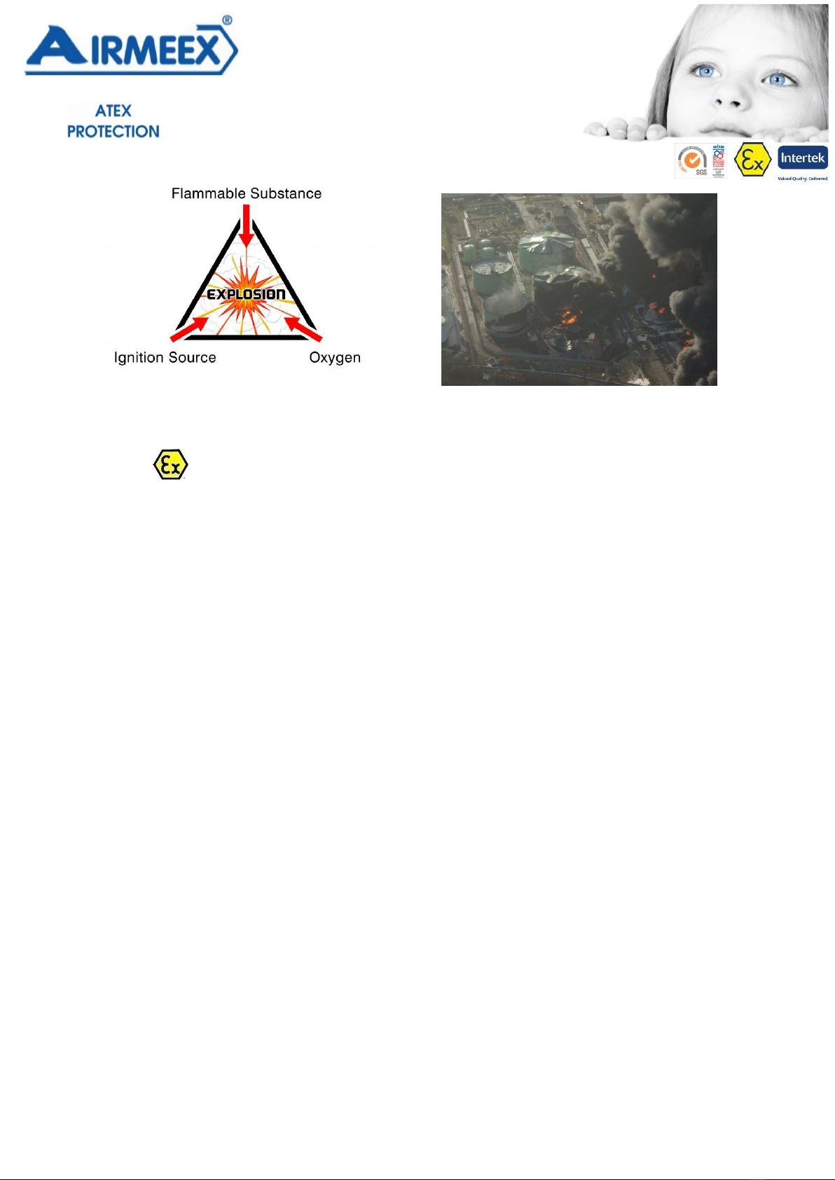
While analyzing risk of explosion processes and their interaction must be considered. In
addition, during the analyzing we have to know criterias of security of flash point of
chemical material, intensitygas and vapour as for that density, ignition point by oneself,
boiling point, explosion limit. Process description and chemical security parameters
should be included in document.
b) the likelihood that explosive atmospheres will occur and their persistence,
Primarly, substitution, concentration limiting and inert methods should be implemented
for preventing explosion atmosphere
c) the likelihood that ignition sources, including electrostatic discharges, will be present and
become active and effective,
With EN1127-1 Standard (Explosion atmosphere –Avoiding explosion and protection –
Chapter 1: Basic concepts and methodology) evaluate igniter sources that active in dangerous
area, equipments which use in this area should be choisen according to zone classification. the
scale of the anticipated effects.
Places which are or can be connected via openings to places in which explosive atmospheres
may occur shall be taken into account in assessing explosion risks.
There must be some prevention for decreasing the effect of explosion for a possible
explosion (durable design for explosion, explosion coveres, pressing and isolating the
explosion systems )

8
C) CLASSIFICATION OF PLACES WHERE EXPLOSIVE ATMOSPHERES
MAY OCCUR
Equipments that use in dangerous area which is possible about flammable gas or vapour risks
should be choosen and set up properly so classifying zones that subject must be correctly.
Consequently, zones and equipments should be compatible.
According to standard that TS 3491 EN 60079-10(General rules for electrical devices that use in
explosive gas atmosphere: ) dangerous area is defined: There is an explosive gas atmosphere (or
possible atmosphere) which need important precaution for using and setting up the devices in
that atmosphere.
Hazardous places are classified in terms of zones on the basis of the frequency and duration of
the occurrence of an explosive atmosphere.
Zone 0
A place in which an explosive atmosphere consisting of a mixture with air of flammable
substances in the form of gas, vapour or mist is present continuously or for long periods or
frequently.
Zone 1
A place in which an explosive atmosphere consisting of a mixture with air or flammable
substances in the form of gas, vapour or mist is likely to occur in normal operation occasionally.
Zone 2
A place in which an explosive atmosphere consisting of a mixture with air of flammable
substances in the form of gas, vapour or mist is not likely to occur in normal operation but, if it
does occur, will persist for a short period only.
Zone 20
A place in which an explosive atmosphere in the form of a cloud of combustable dust in air is
present continously, or for long periods or frequently.
Zone 21
A place in which an explosive atmosphere in the form of a cloud of combustible dust in air is
likely to occur in normal operation occasionally.
Zone 22
A place in which an explosive atmosphere in the form of a cloud of combustible dust in air is not
likely to occur in normal operation but, if it does occur, will persist for a short period only.

9
Table 1:
ZONE
Sustainability, t (Saat/Yıl)
Possibility, P (Yıl-1)
ZONE 0/20
t > 1000 hour/year
P > 0,1
ZONE 1/21
10 hour/year < t < 1000
hour/year
0,1 > P > 10-3
ZONE 2/22
t < 10 hour/year
10-3 > P > 10-5
D) Criterias About Counting Dangerous Area
a) Discharge Sources
It can be described as in such occurring explosion gas place that contain flammable gas, vapour
or liquid get off point.
b) Discharge Degrees
There are three essential discharge levels according to descending sort of occurring explosion gas
place frequency and possibility.
1) Sources that discharge continuously
• Surface of a flammable liquid which is belong to fixed roof tank and permenant ventilation to
atmosphere,
• The surface of a flammable liquid that always or long time open to atmosphere (water/oil
seperator etc.).
2) Sources that main discharge
• In a routine work expectation about spreading flammable material of pump, compressor and
valve mat,
• Water disposal point that possible spreading flammable object and positioned inside a box
while disposal occurring to atmosphere in normal work.
• Taking sample point that spreading a flammable object to atmosphere in a normal work,
• Discharge valves, ventilation valves and other spaces that spread a flammable object to
atmosphere in a normal work.

10
3) Sources that secondary discharge
• There is not an expectation about spreading of flammable object while pump, compressor and
valve mat is working.
• Flanges, connections and pipe connections parts that has not an expectation about spreading
flammable object in a normal routine work.
• Taking sample point which has not an expectation about spreading flammable object to
atmosphere in a normal routine work,
• Discharging valves, ventilation valves and other spaces which has not an expectation about
spreading flammable object to atmosphere in a normal routine work.
c) Discharging Speed of Gas and Vapour
Spreading limit of dangerous zone is zone as much high of discharging speed
Discharging speed is depend on conditions that below.
a) Geometric shape of discharging source
This condition is about physical properties of discharging source, for instance, open surface or
leaking flange.
b) Movement speed of discharging
For a definite discharging source, discharging speed increase with discharging movement speed
as parallel
c) Intensity
If intensity of flammable gas or vapour that spreading mixture increase, discharging speed
increase.
d) Volatility of flammable liquid
In fact, this case depend on vapour pressure and heat of evaporation. If there is not any
information about vapour pressure, boiling point or flashing point can be taken as a guide. Zone
spreading limitation is high as much as low of flashing point
e) Heat of Liquid
Heat of vapour pressure increase thus, discharging point increase because of evaporation
d) Lower Explosion Level (LEL)
Relation between LEL and dangerous zone is how dangerous zone is very big as much as when
LEL is very low for a determined spreading volume.

11
Ammonia discharging which has 15% LEL degree, sweep in the open air and because of this,
explosion gas atmosphere limits is very small that not considered and neglected.
e) Ventilation
Normally, when ventilation increase, spreading of zone decrese
Obstacles to ventilation can be a caused for increasing spreading of zone
f) Relative Density After Discharging of Gas and Vapour
If gas and vapour is lighter than air, they move to upward. If heavy significantly, they will be
collected at floor.
Limits of horizontal spreading of Zone increase with relative density that increase at floor and
increase with relative density which decrease upward of the source.
EXPROOF EQUIPMENT PROTECTION TYPES
•“i” type protection, intrinsic safety
•“ia” type protection, intrinsic safety for more than one malfunction
•“ib” type protection, intrinsic safety for one malfunction
•“d” type protection, flameproof
•“e” type protection, increased safety
•“p” type protection, pressurization protection
•“q” type protection, sand filling
•“o” type protection, oil immersion
•“m” type protection, encapsulation
•“n” type protection, non-sparking protection
•“s” type protection, special type of protection

12
Protection Types According to Zones
For Zone 0 protection type of equipment: ia, s
For Zone 1 protection type of equipment: d, e, ib, o, p, q, m
For Zone 2protection type of equipment: n
Table 2: Table 3:
POSSIBLE IGNITION SOURCES
Hot Surfaces: If explosion zones interact with hot surfaces, ignition can occur. Hot surface is
not adequate a source as an ignition soruces, also a dust coat which interact with hot surface or a
flammable solid can be a source for explosion zone.
Flame and hot gases (inclusive hot spalles): Flames are relevant with burning reaction that
over 1000°C. Hot Gases occur as a reaction output, and when there are flames with dust or soot
solid spalles occur. Flammes, its output that hot reaction or high degree gases can ignite an
explosion place.
Sparks that as mechanical: Grind that friction, fragmentation or erosion operation’s reason,
parts leave form solid products and become hot because of energy that used for separation
operation. These pieces which as iron or steel if involve, these reducibility materials can reach a
very hot situation. With these pieces (sparks), flammable gases and vapours, some dust-air
mixtures can be ignited. Dust which accumulated, sparks can burn without any flamme and this
situation can constitute an ignition source for explosion zone.
Electrical materials: When uses of electrical materials, electrical sparks and hot surfaces can be
as an ignition source. Electrical sparks originated because of reasons that below:
TEMPERATURE CLASSIFICATION
TEMPERATURE
CLASS
Maximum Surface
Degree
T1
4500C
T2
3000C
T3
2000C
T4
1350C
T5
1000C
T6
850C
GAS GROUPS
Gas Group
Gas Type
I
Methane
IIA
Propane
IIB
Ethylene
IIC
Hydrogen/Acetylene

13
- Turning on / off electrical circuit,
- Slack connection,
- Uncontrolled electricity.
Uncontrolled Electricity and Cathodic Corrosion Protection:
-Uncontrolled electricity, systems which follow electric or parts of them;
- As rotation flow in energy production systems –especially electrical rail line and immediate
vicinity- for instance,electric systems compounds as cable protector which is laid rail and
underground when decrease the rotation flow
- Short circuit which occur thanks to electric wiring or as a result of short circuit to the ground,
- As a result of magnetic induction (Near electrical wiring the high flow or radio frequency),
- As a result of strike of lightning.
When the parts separate, connect or bridge which belong to a system that carry uncontrolled
electric,even in a situation as some light potential differences, an explosion zone can ignite
because of electrical sparks and/ditch. Ignition also can be because of heating up this electric
current way. When using of compressive current cathodic corrosion, ignition risk that indicated
above is possible. But, when use anode is abraded, unless anodes are not aluminium or
magnesium, there is not a possibility about ignition risk because of electrical sparks source.
•Static Electricty: Static electricity discharging which cause to fire can be under specific
conditions. Discharging which is formed pieces that charged, isolated conductive can cause to a
fire because of sparks.
•Lightning: In a situation that lightning in an explosion zone, always there will be an
ignition. In addition, due to high temperature that lightning conductive reach, there will be a
possibility of ignition. From the lightning place there will be a huge conduction out and these
conduction can produce sparks near the flashing point. Even there is not any lightning,
thunderstorm, equipments, protection systems and components can cause to high voltage.
•Adiabatic incarceration and shockwaves: When adiabatic incarceration occur, there can
be high temperature for explosion zone in shockwaves. Virtually, temperature increase is not
depend on differences between pressure, is depend on proportion of pressure
Note 1 –There can be an explosion because of ignition with oiling and oil waste in high
pressure. These oils waste is located in air compressor’s pressure line or container that belong
these compressors. For instance, during high pressure gas fall into disuse to pipeline there will
occur shockwaves. In this process shockwaves is transmitted to low pressure zone faster than
speed of sound.
There can be high temperature, when shockwaves, elbow pipes, tight parts of elbows, connection
flanges, close valves etc. rotate to different way, twisted from their side.

14
Note 2 –High incidence of reduced gases under the (for instance, pure oxygen or high oxygen
concentration gas places) inclusive equipment, protection systems and components adiabatic
incercaretion movement and shockwaves or even normal flows compose an ignition point.
Consequently, oils, joints and production tools can ignite. If this ignition cause to damage of
equipments, protection systems and components, explosion zone can ignite
•Exothermic reaction (inclusive combustibility dust automatically): Exothermic
reaction; speed of occurring heat can be as task of combustibility soruce when lost speed more
than heating to environment. Many chemical reaction has a property like exothermic. The subject
that reaction has a high temperature, volume/surface ratio of reaction system, temperature of
place and time of reaction with other parameters. This high temperatures can cause to iginition of
explosion zone and/or normal.
- Unless there is not any proof about searching of independent explosion when there are
mixtures between lightning or flammable material and air, These materials accept as ‘‘ Items that
create an explosion
- In a place that inclusive flammable dust which layer and batch is consider as “ other source that
create an explosion zone ’’.
POSSIBLE EFFECTS OF EXPLOSION
After a while from explosion, there will be a high pressure wave and take action. This is static
addition pressure ( more than normal atmosphere pressure ). After these shockwaves, there will
be a pressure that is created by powerful winds. This is dynamic pressure.
Static addition pressure demolish targets (for example, buildings), also following powerful winds
cause to many damages(dynamic pressure).
Human body can resist to high addition pressure. But dynamic pressure blow up people and
objects, so this cause to death because objects that flyaway will be clash on air. People death can
occur direct and indirect way after that explosion as below.
•Buried in in the wreckage;
•Movement to inside because of sudden and high pressure especially is effected organ
that air inclusive. For instance, air is gotten to lungs, seen edema, in a couple of minutes death
occur.
•Flying of reason that dynamic pressure, collision of floaters, drowning in dust cloud,
etc.
People that exposed to a 5 psi explosion, 1% of them burst eardrum, in 45 psi this proportion is
99%. In 15 psi there is a damage to lungs and between 35-45 psi pressure death proportion is 1%,
in 55-65 psi this proportion is 99%

15
Table 4:
Addition Pressure (psi)
Wind Speed (km/per hour)
Reason
1
60
Building get damage, flying object
damage to people
3
160
Wall demolish, houses get many
damages and people outside die
5
260
Normal Building demolish, steel
construction get damage
10
465
Factory, association and buildings
demolish. Tile and wood of house
fly
20
670
Everything fall down
TECHNICAL PRECAUTION AGAINST EXPLOSION
Primary Precaution: These cautions are taken for prevent explosion zone.
•Materials that have lightning properties should be changed with not have the
properties, if it is possible.
•Limiting the concentrations
•Made ineffective
•prevent and limiting the explosion zone where close unite , sınırlandırma
•Using gas alarm
Secondary Precution: These preventions are taken for wipe spark source up. Sparks sources are
determined with separating place to explosion zone. Prevention is taken according to these
sources.
Tertiary Precution: These preventions are taken for reduce effects of explosion.
•Design that durable for explosion.
•Discharge the explosion.
•Pressure the explosion.
•Block spreading of explosion and flame.

16
1.5 MANUFACTURER'S RESPONSIBILITY
Regulation on the Equipment and Protective Systems Intended For Use In Potentially Explosive
Atmospheres (2014/34/AB), III. Part, Item 8, describes Airmeex Industry’s responsibility.
1.6 USER’S RESPONSIBILITY
The user that has got Ex equipment or work machine, so related business, have to audit
obsolescence due to use in operating conditions and Atex compliance continuity of Exproof
Equipment and system that is produced according to Regulation on the Equipment and
Protective Systems Intended For Use In Potentially Explosive Atmospheres (2014/34/AB)
Every intervention that be done to repair and maintenance in warranty coverage or out of
warranty coverage of every Ex equipment and work machine that is produced and converted by
Airmeex should be within the knowledge of Airmeex in order to protect Atex compliance
continuity. This auditing and maintenance should be done by staff that has practice of
installation, educated about Atex protection and classification principles. Because of the repair of
ex-proof tools requires special techniques, it is very important to record the transactions that
made carefully. So the user should not forget that the modifications made on the machine break
the exproof feature of equipment.
2. USAGE
2.1 PRE-START CHECK
First of all, check that the emergency stop button is pushed or not and button must be open by
turned inward in pushed position.
A visual control of whether battery connector is installed position must be.
Check that the battery cutter is open
2.2 START
First of all, it is necessary to be seated on the seat because of the system can operate smoothly.
For 3 seconds after turning the ignition, the system that is called Canbus is expected to
communicate between the brains and systems on the vehicle.
It is checked whether the system gives any error code from the screen of the machine.
If there is error code, it is determined what the code means by going to the relevant document of
the machine and necessary measures are taken.
The lift-boom-tilt arms on the machine are checked and the use of the machine is started.
2.3 STOPPING
Standart stopping: stopping of truck occurs by closing the contact.
Emergency stopping: the entire system is turned off by closing the battery cutter.
Note: It is advisable to close the battery cutter when the machine is not used.

17
3. ELECTRICAL AND NON-ELECTRICAL EX EQUIPMENT
There are quantities and group category descriptions of certified Ex equipments that are
produced by Airmeex and are used on the machine at the following list.
Table 5:
Ex EQUIPMENTS ON THE MACHINE
QUANTITY
CERTIFICATE
NUMBER
PRODUCT NAME
REFERENCE
STANDARD
ATEX GROUP
CATEGORY
DESCRIPTION
DRAWING
NUMBER
1
TSE 17 ATEX 0069X
ATEX ELECTRIC BOX
MODEL 6
EN 60079-0
EN 60079-1
II 2 G Ex db IIB T6 Gb
E5299-400
11
MP 17 ATEX 0110X
ATEX SOLENOID
EN 60079-0
EN 60079-1
II 2GD Ex db IIC Gb
E5299-601
1
MP 18 ATEX 0219X
ATEX BATTERY
CONNECTOR
EN 60079-0
EN 60079-1
II 2 G Ex db IIC T5
Gb
S5027-100
8
MP 17 ATEX 0121U
ATEX ELECTRIC
BUTON
EN 60079-0
EN 60079-1
II 2 G Ex d IIC Gb
S5114-100
1
MP 17 ATEX 0124X
ACCUMULATOR
BATTERY
EN 60079-0
EN 60079-7
II 2 G Ex eb IIB T* Gb
E5299-500
SCA 12 ATEX 018 X
CABLE GLAND
EN 60079-0
EN 60079-1
EN 60079-7
II 2G Ex d IIC / Ex e
II T6
S5029-100
CER A
1
MP 17 ATEX 0108X
FLASHING BEACON
EN 60079-0
EN 60079-1
II 2 G Ex db IIC T4
Gb
S515-950
1
MP 17 ATEX 0106X
ELECTRIC MOTOR
MODEL 2
(HYDRAULIC
MOTOR)
EN 60079-0
EN 60079-1
II 2 G Ex db IIB T6
Gb
E5299-300
1
MP 17 ATEX 0106X
ELECTRIC MOTOR
MODEL 2
(DIRECTION
MOTOR)
EN 60079-0
EN 60079-1
II 2 G Ex db IIB T6
Gb
E5299-100
1
MP 17 ATEX 0106X
ELECTRIC MOTOR
MODEL 2 (DRIVING
MOTOR)
EN 60079-0
EN 60079-1
II 2 G Ex db IIB T6
Gb
E5299-200
1
MP 17 ATEX 0119X
ATEX CAP
EN 60079-0
EN 60079-1
EN 60079-7
II 2 G Ex db IIC Gb
S5029-105
2
MP 17 ATEX 0129X
RECTANGLE LIGTH
EN 60079-0
EN 60079-1
II 2 G Ex db IIC T6
Gb
S5051-100
1
SİRA 05ATEX2084X
BUZZER SOUNDER
EN 60079-0
EN 60079-11
II 1 G Ex ia IIC T4 Ga
1
PTB 01 ATEX
1061U
‘e’ TYPE BOX
II 2 G Ex e IIC Gb

18
3.1 ELECTRICAL EQUIPMENTS
ELECTRIC BOX
Electric Boxes are suitable according to EN60079-1 “d” type protection, flameproof and its
protection type is II 2 G Ex d IIB T6 Gb
This protection provides exproof protection for all of battery insulator, control unit, contactor,
braker and electronic parts. Internal security interfaces are also installed in the electric box. These
units provides actual safety current and voltage for control of truck.
The battery connectors are protected by an explosion-proof enclosure.
To open the Electrical box:
> Remove all the screws to open the cover.
> When you open the trunk, please, take care to not damage the flameproof seal (on the lid and
on the electrical box).
To close the Electrical box:
Clean the flameproof seal (box and lid).
Check the flameproof seal surface (there should not be any damage).
Apply water-based silicone grease and no dye on the flameproof seal.
Screw and tighten all cover screws in accordance with the torque settings.
Checkpoints:
Watch the flameproof seal each time you open the enclosure.
Check the tightness of the cable glands.
Check the sensor control devices every 6 months.

19
Separate each security one by one, make sure each indicator is open and truck is stopped,
the warning lamps have to turn when you do this.
Check the calibrations of the temperature sensors once a year according to the recorded
values.
Brakers are placed in the box.
Check the control system every 3 months.
DO NOT OPEN THE ENCLOSURE INTO DANGEROUS AREA
DIRECTION MOTOR
DRIVING MOTOR

20
HYDRAULIC MOTOR
The motors are protected according to the protection mode in Ex "d" (EN60079-1). A
temperature sensor continuously measures the surface temperature of the explosion-proof motor
housing. The motors are in envelopes that require, the same level of care during the
opening/closing as the electrical box.
The safety boxes prevent explosion when there is any spark or gas leak.
DISASSEMBLY
During removal, if clean surface which imperilment had damage, should be.
Exproof surfaces are oiled.
Loosen cable glands and pull entry cable carefully.
Remove screws which around motor and then take out end cover
Celan up all dust and controll all cable.
If there seems any scratch on cable, change all
MONTAGE
Check all screws affixed or not. During the body which ready for closing
Don’t change screw from class 8,8 or shorter than this
Oiled exproof surfaces. (Oil which is not include moligrafit).
Check the motor leave from chassis or not.
Check fixation torc of scrwes.
MAINTENANCE
Once in every 250 hours:
- Check the outside of the motor
- control the isolation between motor and
This manual suits for next models
1
Table of contents
Other Still Forklift manuals

Still
Still FM-X SE User manual

Still
Still EXV 10 Basic User manual

Still
Still FXD 20 User manual

Still
Still GX10 Manual

Still
Still STEDS R20-15 Instruction manual

Still
Still MX-X User manual

Still
Still RX60 25-35 User manual

Still
Still GX-X User manual

Still
Still OPX 20 Operating instructions

Still
Still RX60-16 User manual