Still FM-4W 20 User manual

Original instructions
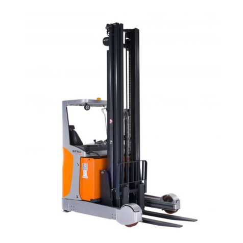
Reach truck
FM-4W 20
FM-4W 25
first in intralogistics
EN - 159007 - Rev. A - 01/2015
UniCarriers Manufacturing Sweden AB
SE-435 82 Mölnlycke
Phone +46 (0)31 98 40 00
www.atlet.com

The content of this manual is protected by copyright law and may not be copied,
fully or in part, without written permission.
The material has undergone careful examination with regard to correctness. We
reserve the right to make changes.
©Copyright UniCarriers Manufacturing Sweden AB, 2014
Instruction Handbook UFW — D008453, B, GBR, ForTranslation

TABLE OF CONTENTS
01 INTRODUCTION................................................................................................... 6
Instruction Handbook ...................................................................................... 6
Conversion table for forklift truck models......................................... 6
02 TRUCK MODIFICATION................................................................................. 7
Truck modification.............................................................................................. 7
03 ENVIRONMENTAL CONSIDERATIONS............................................ 8
We respect the environment...................................................................... 8
04 THE SUPERVISOR............................................................................................. 9
Foreman’s responsibility............................................................................... 9
05 TRUCK DRIVER................................................................................................. 11
Authorization to drive a truck.................................................................. 11
Driver requirements....................................................................................... 11
Inspection of the truck ................................................................................. 11
06 MACHINE PLATES.......................................................................................... 12
Explanation of machine plates .............................................................. 12
Location of machine plates...................................................................... 12
07 DESCRIPTION OF THE TRUCK........................................................... 13
UFW Tergo four-way truck........................................................................ 13
Driver environment......................................................................................... 13
Stability Support System, S3-1............................................................. 20
Stability Support System, S3-2............................................................. 21
Weight indication ............................................................................................. 21
Dynamic Curve Control (DCC).............................................................. 22
Active Spin Reduction, ASR (option)................................................ 22
Fork Safe Zone System (option).......................................................... 23
Cab (option)......................................................................................................... 23
Options.................................................................................................................... 27
08 BATTERY................................................................................................................. 29
Specifications..................................................................................................... 29
Battery charging............................................................................................... 29
Maintaining and changing the battery.............................................. 31
Battery servicing .............................................................................................. 32
09 TRUCK COMPUTER ATC .......................................................................... 33
General................................................................................................................... 33
Symbols and characters on the display.......................................... 33
Instruction Handbook UFW — D008453, B, GBR, ForTranslation

TABLE OF CONTENTS
Keyboard ............................................................................................................... 34
Battery indicator ............................................................................................... 35
Error messages ................................................................................................ 35
Warnings................................................................................................................ 36
Functions............................................................................................................... 36
Change language............................................................................................ 36
Driver parameters........................................................................................... 37
Trucks equipped with options................................................................. 38
10 DRIVING INSTRUCTIONS......................................................................... 45
Starting the truck ............................................................................................. 45
Driving instructions......................................................................................... 45
Switching off the truck.................................................................................. 47
Normal or crawler mode............................................................................. 48
11 GENERAL LOADING AND UNLOADING
INFORMATION.................................................................................................... 49
Responsibility for the load ........................................................................ 49
Responsibility for others............................................................................. 49
Maximal load ...................................................................................................... 49
Picking up a load ............................................................................................. 49
12 STACKING.............................................................................................................. 50
General................................................................................................................... 50
Trucks with reach capability .................................................................... 50
Trucks with mast tilt ....................................................................................... 50
13 MAINTENANCE OF THE TRUCK........................................................ 51
Daily maintenance (before each shift)............................................. 51
Daily Service (after each shift) .............................................................. 51
Weekly inspection ......................................................................................... 52
Preventive maintenance ............................................................................ 53
14 SERVICING AND MAINTENANCE ..................................................... 54
Service personnel........................................................................................... 54
Safety instructions for maintenance.................................................. 54
Maintenance intervals.................................................................................. 54
Maintenance instructions........................................................................... 61
15 SAFETY REGULATIONS............................................................................ 67
The authority and obligations of the truck
driver.................................................................................................................. 67
Getting in and out............................................................................................ 67
Driving the truck ............................................................................................... 67
Instruction Handbook UFW — D008453, B, GBR, ForTranslation
TABLE OF CONTENTS
Speed (UFW) ..................................................................................................... 71
Transportation security................................................................................ 72
Moving the forks (UFW) ............................................................................. 73
Normal operating conditions................................................................... 74
Exceptional operating conditions......................................................... 74
Work in hazardous environments ....................................................... 74
Parking.................................................................................................................... 74
When lifting the truck.................................................................................... 75
Assembling and putting into service ................................................. 76
Temporarily taking the truck out of service................................... 76
Taking the truck out of service............................................................... 77
Swinging loads.................................................................................................. 77
Installing the fire extinguisher ................................................................ 78
In the event of accidents............................................................................ 78
Noise/Sound levels........................................................................................ 78
Vibrations .............................................................................................................. 78
Climatic conditions ......................................................................................... 78
Work platforms.................................................................................................. 78
Overhead guard ............................................................................................... 79
Protective shoes .............................................................................................. 79
Lighting ................................................................................................................... 79
Additional units/Trailers .............................................................................. 79
Safety and warning signs.......................................................................... 79
16 DIMENSIONS ....................................................................................................... 81
Dimensions.......................................................................................................... 81
17 WEIGHT.................................................................................................................... 83
Weight...................................................................................................................... 83
18 ORDERING HANDBOOKS AND MANUALS.............................. 84
Ordering a Spare Parts Catalogue..................................................... 84
Instruction Handbook UFW — D008453, B, GBR, ForTranslation
01INTRODUCTION
6
Instruction Handbook
This Instruction Handbook contains information that you, as
user of the truck, must be aware of in order to avoid/minimise
the risk of injury/damage to yourself or the truck. You are also
responsible to the company management, other people and
objects in your environment. You should therefore carefully read
all the way through this handbook before starting the truck for
the first time.
The Instruction manual describes a truck with standard
equipment, customer modifications may have been fitted.
It is not obvious that the options that are described in the
Instruction Handbook are suitable for all truck models. Contact
your truck supplier for information.
Our products are constantly being developed and renewed, we
therefore reserve the right to make alterations without prior
notice.
Thank you for choosing UniCarriers Manufacturing Sweden
AB as your truck supplier.
UniCarriers Manufacturing Sweden AB
We have been manufacturing trucks since 1958. Quality,
operational safety and innovation have made us a leading
worldwide truck supplier.
UniCarriers Genuine Parts
To maintain the reliability that UniCarriers promises, insist on
UniCarriers genuine replacement parts. Only UniCarriers
genuine replacement parts guarantee correct operation, long
life and the right to a warranty.
Declaration of conformity
UniCarriers Manufacturing Sweden AB, SE-435 82 Mölnlycke,
Sweden, declares under its sole responsibility that the supplied
products are in compliance with the relevant safety
requirements of Directives 2006/42/EC and 2004/108/EC. The
risk analysis is based on ISO 3691-1. The Certificate for
Declaration of Conformity accompanies every machine. It is
important that this remains with the truck.
Manufactured by:
UniCarriers Manufacturing Sweden AB, Metallvägen 9,
435 82 Mölnlycke, Sweden, Telephone +46 (0) 31 98 40 00,
Sales and customer service via:
STILL GmbH, Berzeliusstrasse 4, 22113 Hamburg, Germany.
Conversion table for forklift truck models
Commercial name Model name
FM-4W 20 UFW 200
FM-4W 25 UFW 250
Instruction Handbook UFW — D008453, B, GBR, ForTranslation
TRUCK MODIFICATION02
7
Truck modification
NOTE!
Unauthorized truck modification is not permitted.
No modifications or alterations to a powered industrial truck,
which may affect, for example, the capacity, stability or safety
requirements of the truck shall be made without the prior written
approval of STILL, its authorized representative, or a successor
thereof. Contact an authorised STILL distributor before making
any modification or alteration to your industrial truck that may
affect, for example, braking, steering, visibility and the
connection of separate load units. After approval has been
given by STILL, its authorized representative, or a successor
thereof, the plates, decals, tags and operation and maintenance
handbooks stating the truck capacity shall also be changed
appropriately.
Only in the event that STILL is no longer in business and there
is no successor in the interest to the business, may the user
perform a modification or alteration to a powered industrial
truck. This applies on condition that the user:
• arranges for the modification or alteration to be designed,
tested and implemented by one or more engineers who
are experts in industrial trucks and their safety
• maintains a permanent record of the design, test(s) and
implementation of the modification or alteration
• approves and makes appropriate changes to the capacity
plate(s), decals, tags and Instruction Handbook
• affixes a permanent and readily visible label to the truck
stating the manner in which the truck has been modified or
altered, together with the date of the modification or
alteration, and the name and address of the organization
which performed the task.
Instruction Handbook UFW — D008453, B, GBR, ForTranslation

03ENVIRONMENTAL CONSIDERATIONS
8
We respect the environment
The majority of our products consist of steel, and can be
completely recycled.
Environmental impact
All products have an impact on the environment throughout
their entire life cycle.
The consumption of energy when in use is one of the most
important factors that influences the environment.
Through correct care, maintenance and use the consumption of
energy can be reduced, thereby reducing the environmental
impact.
Waste
Waste material in conjunction with repairs, maintenance,
cleaning, or scrapping, must be collected and disposed of in an
environment-friendly way and in accordance with the directives
of respective countries.
Such work should only be carried out in areas intended for this
purpose.
Recyclable material should be taken care of by specialised
authorities.
Environmentally hazardous waste, such as oil filters, hydraulic
oil, batteries and electronic equipment, can, if handled
incorrectly, have a negative effect on the environment and
human health.
Instruction Handbook UFW — D008453, B, GBR, ForTranslation
THE SUPERVISOR04
9
Foreman’s responsibility
1. It is the responsibility of the supervisor, on behalf of the
company management, to ensure that the truck is driven
and used correctly.
2. The supervisor is responsible for compliance with the
requirements placed on the driver, refer to Driver
requirements page 11.
3. It is the duty of the supervisor to instruct and to ensure that
driver instructions are followed.
4. The supervisor must supply, and the driver of the truck
must sign for the following:
• Instruction Handbook for STILL electric fork lift trucks
• other necessary instruction handbooks.
The supervisor must also read and be familiar with the
appropriate instruction handbooks.
The fork lift truck must be insured with at least third party
insurance if this is a national authority requirement.
Maintenance personnel
NOTE!
The daily maintenance and certain service is to be
carried out by the driver after he/she has received
sufficient training in the construction and maintenance
of the truck. Continuous regular servicing should be
performed by an authorized servicing organization. To
ensure efficient and satisfactory servicing of the truck,
please contact the STILL service department or an
authorized distributor. STILL can offer a service
agreement for continuous maintenance.
Conditions of use
The truck may be driven under the following conditions:
• indoors
• under a canopy, see: Climatic conditions page 78.
• on a flat, hard and smooth surface
• with the maximum floor loading checked and not exceeded
• normal operating temperature, refer to Climatic conditions
page 78
• good visibility, adequate lighting and approved routes.
• use in still air. If draughts or wind are present, load
handling and transportation must be adapted to suit the
prevailing conditions.
Instruction Handbook UFW — D008453, B, GBR, ForTranslation
04THE SUPERVISOR
10
WARNING!
A truck operating in an area where there is a risk of
fire, explosion, or in any other high risk area, must be
specially equipped for the purpose. Trucks are not
normally equipped for these situations.
Instruction Handbook UFW — D008453, B, GBR, ForTranslation

TRUCK DRIVER05
11
Authorization to drive a truck
The employer must ensure that the employee has the required
training and knows what must be observed in order to avoid
risks while working. The employer must take into consideration
an employee's suitability for the work in question. It is therefore
necessary that a person engaged as a driver completes the
appropriate truck driver training, both theoretical and practical,
that corresponds to the work assignments the driver is expected
to undertake after training. Further training may be required in
the event of major changes in work assignments. The employer
should give the employee written authorization to drive the truck
- as well as a written outline of the extent of his/her duties.
Driver requirements
The truck driver shall have the mental and physical capacity
required for the job. The driver shall also be aware of everything
that is relevant to the handling and manoeuvring of the truck,
traffic regulations and any other relevant instructions. The driver
shall have the permission of the supervisor to drive the type of
truck in question and be specially trained for the work and the
traffic conditions involved.
The responsibilities of the driver in specific markets
The following apply in respect of the driver's responsibilities
concerning the use of fork lift trucks:
• Australia: Users shall follow the requirements of AS
2359.2.
• North America: Users shall follow the requirements of the
applicable part of ANSI/ITSDF B56.
Inspection of the truck
• The driver of the truck is responsible to the supervisor, for
ensuring that the truck is kept in good working order.
• Daily maintenance shall be carried out carefully before the
start of each shift. See section Maintenance of the truck
page 51.
• Any faults must be reported to the supervisor immediately.
• In order to remain in good working order, the truck shall be
kept clean and properly maintained. The truck must be
checked at regular intervals in accordance with the service
instructions.
• Check that no safety equipment has been modified or put
out of service.
For optimum performance and so as not to invalidate the
warranty, use only UniCarriers genuine replacement parts!
Instruction Handbook UFW — D008453, B, GBR, ForTranslation
06MACHINE PLATES
12
Explanation of machine plates
The Machine plate contains important information. Read it
carefully! The permitted load shall not be exceeded.
Machine plate Load limit plate
Figure 1. Machine plate and load limit plate
1. Model designation
2. Type Serial No./Version
(S=Special version)
3. Year of manufacture
4. Actual capacity, Q
5. Load centre distance, D
6. Lift height for fork lift, H
7. Battery voltage
8. Weight without battery
9. Minimum battery weight
10. Maximum battery weight
11. Reference number
12. Unit designation (option)
Total truck weight = Weight without battery + Battery weight +
Load + Driver
Location of machine plates
The machine plate is located behind the driving seat. The load
limit plate is located on the overhead guard pillar, in front of the
driver.
Figure 2. Location of machine plates
A. Load limit plate B. Machine plate
Instruction Handbook UFW — D008453, B, GBR, ForTranslation
DESCRIPTION OF THE TRUCK07
13
UFW Tergo four-way truck
UFW Tergo (U** Tergo) is an electric four-way truck, specially
adapted for handling long and bulky loads and different types of
load carriers. Driving in four directions is possible due to load
wheel rotation. The truck operates both with the load carried in
front of the straddle legs and with the mast retracted for
minimum aisle width. The truck is used for stacking in different
storage systems and for transporting load carriers.
Driver environment
Functions
Controls
Figure 3. Foot control
A. Left-foot switch (safety
function)
B. Brake pedal
C. Speed Controller
D. Battery lock for
carriage-mounted battery
Instruction Handbook UFW — D008453, B, GBR, ForTranslation

07DESCRIPTION OF THE TRUCK
14
Figure 4. Controls, dashboard
A. Ergologic joystick
B. Hand operated driving
direction selector (only in
combination with hydraulic
levers)
C. Horn button (only in
combination with hydraulic
levers)
D. Display
E. Keyboard
F. Emergency stop (safety
function)
G. Switch (see Switches G.
page 14)
H. Key switch (option) or
button/indicator lamp to
activate wire guidance
(option)
I. 12 Volt outlet (option)
J. Handle for battery plug
K. Lever for battery changing
system (option)
G1 Camera 1/2 (option)
G2 Floor lift/lower
G3 Options
G4 Work lighting (option)
G5 Camera on/off (option)
Table 1. Switches G.
Rear view camera system for sideways driving (option)
UFW four-way trucks can be equipped with a rear view camera
system which gives the driver a better reverse view during
sideways driving. The rear view camera gives increased
visibility past a long load. Start the camera by pressing the
switch (item G5), and then switch on the monitor by pressing
the button.
Figure 5. Rear view camera monitor
Instruction Handbook UFW — D008453, B, GBR, ForTranslation
DESCRIPTION OF THE TRUCK07
15
Hydraulic functions
To use any of the hydraulic functions, the driver must be sitting
in the driver's seat, so that the seat switch (safety function) is
activated.
Ergologic joystick
Figure 6. Ergologic joystick
Four-way trucks
Control
s
Functionality Movements
A Forks lower/raise Move the complete
control away
from/
towards the driver
B Mast out/in Move the complete
control
towards/
away from the mast
C Tilt up/down Move the control
up/down
D Turning the
steered wheel
clockwise/
counterclockwis
e
Move the control
away
from/
towards the driver
E Fork spreading together/apart Move the control
up/down
F Direction control
switch
forwards/
backwards
Press the button to
obtain the desired
driving direction
G Horn Press the button
Table 2. Control functions
Instruction Handbook UFW — D008453, B, GBR, ForTranslation
07DESCRIPTION OF THE TRUCK
16
Four-way trucks
Control
s
Functionality Movements
H Simultaneous
turning of the drive
and steered
wheels
Press the button and
move control D away
from/
towards the driver
I Options Options
Hydraulic levers (option)
Lever 1 is located closest to the operator.
Four-way trucks
Figure 7. Hydraulic levers, four-way truck
Lever Away from the truck
driver
Towards the truck
driver
1 Lower Lift
2 Mast out Mast in
3 Tilt down Tilt up
4* Steered wheel
assembly
counterclockwise
Steered wheel
assembly clockwise
5 Forks apart Forks together
Table 3. Lever-operated four-way truck
* Holding down the button located above the lever positions the
drive wheel in the same direction as the steered wheel.
CAUTION!
The fork spread function must not be used with any
load on the forks. The forks may misalign and
damage the boom. For the same reason, do not use
this function when the forks are against the supports.
Lift the forks up first.
CAUTION!
The fork spread function is not intended to be used to
clamp a load between the forks.
Instruction Handbook UFW — D008453, B, GBR, ForTranslation
DESCRIPTION OF THE TRUCK07
17
NOTE!
If the truck is equipped with the wider fork spreading
unit, it projects 213 mm out on each side of the truck.
Settings
Instrument panel and arm rest
In order to increase comfort and driver ergonomics, there are a
number of adjustment options. For the operating procedures,
refer also to the instructions in the pocket under the right side
arm rest.
Figure 8. Adjustment of the dashboard and arm rest
A. Press button A to adjust the
complete dashboard forward
or back.
B. Move lever B upwards to
adjust the height of the arm
rest.
Driver seat
The driving seat can be adjusted to suit the driver's weight, size
and seating posture. The adjustments can be performed as
follows.
Instruction Handbook UFW — D008453, B, GBR, ForTranslation

07DESCRIPTION OF THE TRUCK
18
A. Weight adjustment
Fold out the crank on the weight adjustment control A and turn
it until the green marking points upwards while the driver is
sitting in the seat. The springing is then set to suit the weight of
the driver.
B. Locking the backrest tilt
The backrest may be set either to its moving tilt position or its
locked position. Lower lever B to its vertical position to lock the
backrest tilt. The backrest can be locked in any tilt position over
its whole travel.
C. Backrest tilt
When the backrest is in its tilt position (i.e. the lever is
horizontal), its tilt can be adjusted to one of three positions
using lever C. Tilt the backrest back, pull out the lever and place
it in the desired position. Release the backrest. For a more
upright position, move the lever so that it points downwards. So
that the backrest shall be angled more in the non-tilted state,
move the lever so that it is horizontal.
D. Forwards/backwards adjustment
The seat can be moved forwards or backwards by lifting the
handle beneath the seat upwards and at the same time moving
the seat.
G. Lumbar support
The lumbar support is adjusted by pumping up the bladder.
Release air by pressing the button on the bladder.
H. Seat heating (option)
Seat heating is switched on and regulated by rolling the wheel,
located to the left of the seat cushion, up or down.
Neck support (optional for)
Instruction Handbook UFW — D008453, B, GBR, ForTranslation

DESCRIPTION OF THE TRUCK07
19
Figure 9. Adjusting the head rest
The neck support B can be adjusted up or down in steps. To
remove the neck support from the seat backrest, press in latch
A at the rear of the seat back while at the same time pulling up
the neck support. To find the latch, follow the neck support strut
down along the seat back.
Mini-wheel
If the truck is equipped with a mini steering wheel, place the
entire palm of your left hand upon the small knob on the mini
steering wheel, supporting your arm on the armrest. The
armrest is adjusted in accordance with the movements you
make. In order to facilitate getting in and out, the armrest can
be lifted up.
Figure 10. Mini steering wheel, armrest adjustment
A. Adjusting the armrest forwards and backwards
The armrest can be adjusted forwards and backwards by
pressing button A and moving the armrest to the desired
position.
A. Adjusting the armrest height
The height of the armrest can be adjusted by releasing the knob
B and moving the armrest to the desired position. The armrest
is locked into position by tightening the knob.
Instruction Handbook UFW — D008453, B, GBR, ForTranslation
07DESCRIPTION OF THE TRUCK
20
Midi-wheel (option)
The midi-wheel can be adjusted in three directions, height,
horizontally and turning. All these adjustments are made by
releasing the knob (A).
Figure 11. Adjusting the midi-wheel
Stability Support System, S3-1
S3 alternative 1 (S3-1) is an electronic auxiliary and monitoring
system that improves stability and safety when loading and
driving.
Trucks fitted with the S3-1 system have the maximum speed for
driving reduced and certain hydraulic functions limited,
depending on the height of the forks above the floor, the
position of the reach carriage, and in cases where the drive
wheel is turned more than 3 degrees in either direction. If the
truck is started with the forks raised or the reach carriage
extended, an instruction is given on the truck computer display
to lower the forks or to retract the reach carriage. If this is not
done, the truck speed is limited. The speed of operation with
the second and third control levers is also reduced when the
forks are raised.
NOTE!
When a four-way truck is moving sideways, S3-1
does not limit the speed during a turn.
Reducing the risk of tipping sideways
A. When the driver increases speed too quickly or is driving too
fast in combination with sharp turns there is a risk of tipping.
The S3-1 system “thinks ahead” and can immediately
compensate by reducing speed and acceleration.
B. The speed is also reduced when the forks are raised and the
mast pushed out.
Improved control at top speeds
Since the truck is more difficult to steer in the direction of the
forks at high speed, the speed is reduced in this situation.
Reducing the risk of tipping over
Tipping forces are generated when loads are handled at high
heights and when the mast is pushed out and tilted, especially
in combination with the truck moving over the floor. In this
Instruction Handbook UFW — D008453, B, GBR, ForTranslation
This manual suits for next models
1
Table of contents
Other Still Forklift manuals

Still
Still EXD-S 20 User manual

Still
Still RX20 14-20 User manual

Still
Still RX60-16 User manual

Still
Still OPX 20 Operating instructions

Still
Still EXV-CB 06 User manual

Still
Still FXD 20 User manual

Still
Still CX User manual

Still
Still EXG-10 User manual

Still
Still FM-X SE User manual

Still
Still RCD40 User manual

Still
Still EXG-10 User manual

Still
Still ECU-SF-20 User manual

Still
Still EXD-SF 20 User manual

Still
Still RX20 Series User manual

Still
Still GX-X User manual

Still
Still MX-X User manual

Still
Still RX70-40 User manual

Still
Still FXD 20 User manual

Still
Still RX50-13 User manual

Still
Still STEDS R70-16 User manual