STONEX S10 User manual

CS (13/10/2014)-Ver.2-Rev.3 RC/EC/GQ (21/04/2015) –Rev.4 EC (18/01/2016) –Rev.4_2 CS (29/02/2016)
STONEX S10
GNSS Receiver
User Manual
www.stonexpositioning.com

Stonex S10 GNSS Receiver –User Manual 1
Contents
1. Introduction to Stonex S10 GNSS............................................................................................ 2
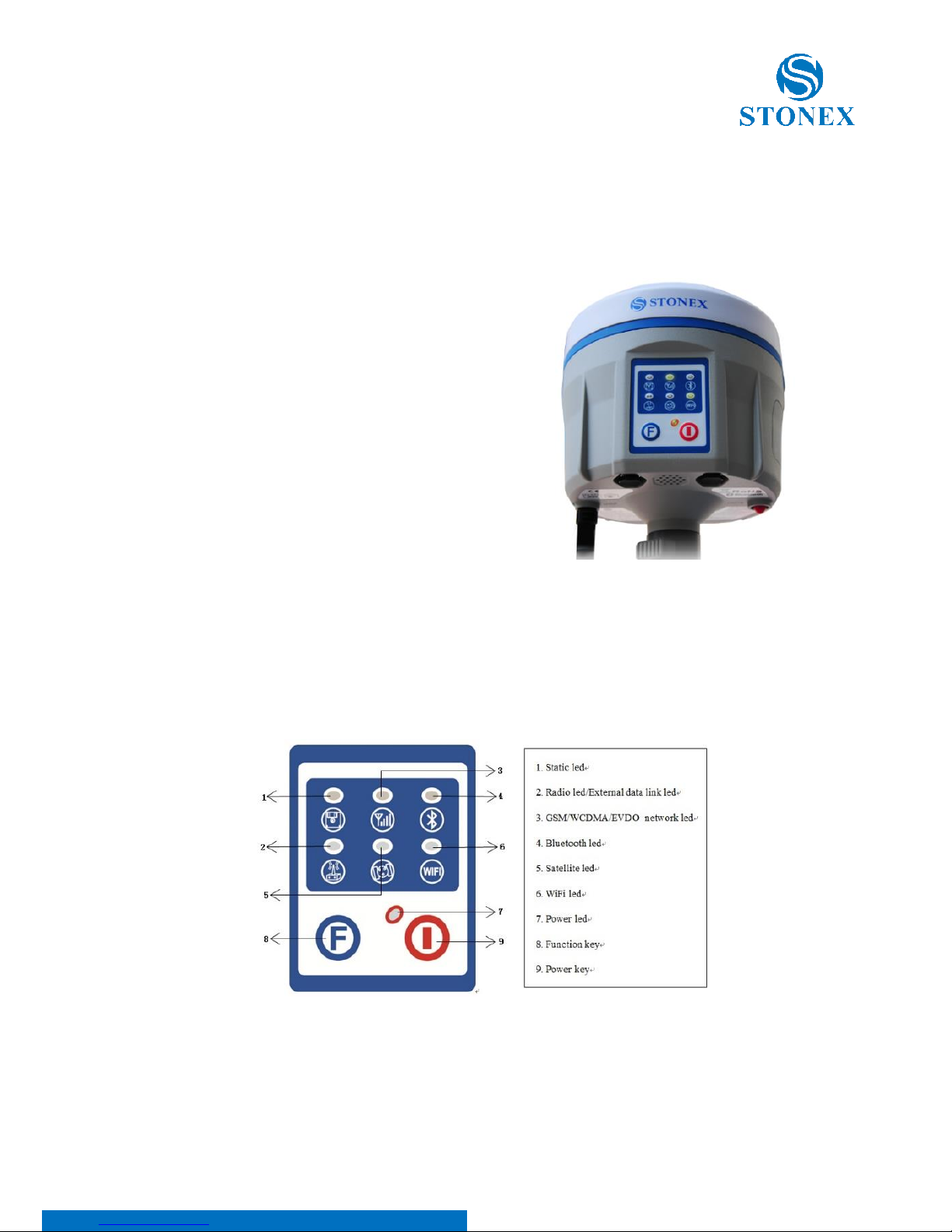
2. S10 panel description.................................................................................................................... 3
2.1. S10 smart panel ...................................................................................................................... 3
2.2. Communications & antennas ports.................................................................................. 7
2.3. The back of the receiver....................................................................................................... 8
3. S10 standard accessories.............................................................................................................. 9
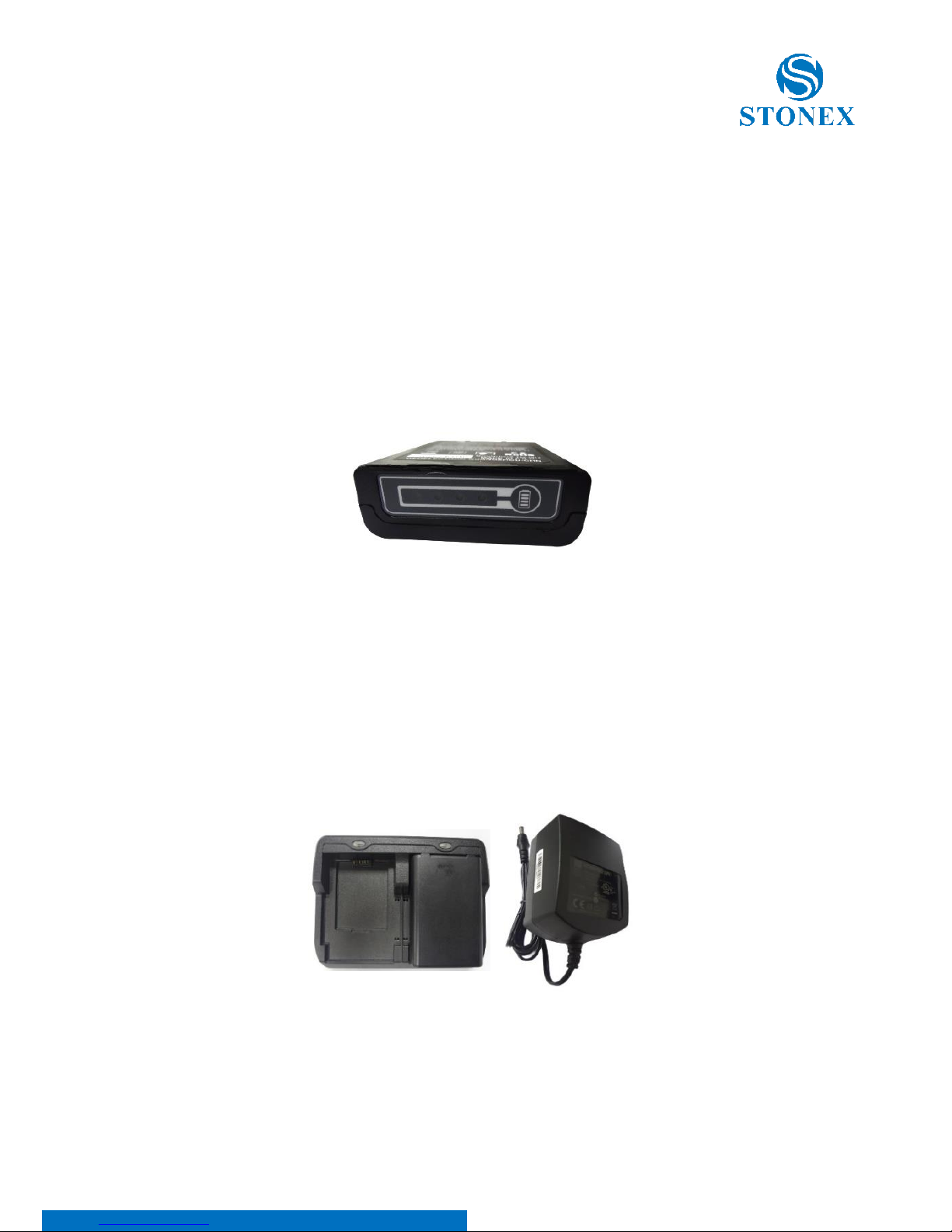
3.1. Power supply............................................................................................................................ 9
3.2. The antennas..........................................................................................................................10
3.3. Cables.......................................................................................................................................11
3.4. Other accessories..................................................................................................................11
3.5. Controller STONEX S4C/H .................................................................................................14
4. S10 Operations...............................................................................................................................15
4.1. The installation of base and rover...................................................................................15
4.2. Working mode settings......................................................................................................16
4.3. How to download static data ...........................................................................................18
5. STONEX® Web UI Applications..............................................................................................20
5.1. How to connect to WebUI.................................................................................................20
5.2. Working modes and device configuration...................................................................24
5.3. Rover mode............................................................................................................................26
5.3.1. Option UHF..........................................................................................................26
5.3.2. Option Network..................................................................................................27
5.3.3. Option “External”................................................................................................ 28
5.4. Base Mode..............................................................................................................................29
5.4.1. Option UHF..........................................................................................................29
5.4.2. Option Network..................................................................................................30
5.4.3. Option External”.................................................................................................. 31
5.5. Device configuration ...........................................................................................................31
5.6 NMEA Settings .......................................................................................................................32
6. Appendix...........................................................................................................................................33
Appendix 1: STONEX S10/S10N electronic bubble and tilt sensor Calibration
procedure........................................................................................................................................33
6.1.1 E-bubble calibration ...........................................................................................37
6.1.2 Azimuth calibration............................................................................................. 37
6.1.3 Declination (compass) calibration....................................................................39
Appendix 2: Default Radio Settings........................................................................................44
Appendix 3: Frequently Asked Questions.............................................................................44
Appendix 4: Technical Specifications .....................................................................................46
Appendix 5: Copyrights, warranty and environmental recycling ..................................49
Appendix 6: Safety Recommendations..................................................................................56

Stonex S10 GNSS Receiver –User Manual 2
1. Introduction to Stonex S10 GNSS
STONEX S10 GNSS introduces revolutionary changes to the technique of
surveying.
Designed with the collaboration of professional Surveyors and technical
engineers teams, Stonex S10 GNSS RTK technology gives the user the
maximum possible reliability in every kind of environment.
Compared with the previous generation GNSS receivers, the new smart Stonex
S10 is introducing innovation in technology, a charming appearance design
and solid magnesium alloy fuselage, incredibly small and light –less than 2Kg
included the battery, resistance to impact and shock absorption function,
good electromagnetic shielding and upscale appearance.
Equipped with a new high accuracy integrated antenna, Stonex S10 fully
supports Beidou (Compass), GPS, GLONASS, Galileo, SBAS (WAAS, EGNOS,
QZSS) signals: no troubles or extra costs for new constellations hardware
upgrades.
The integrated TX/RX UHF radio modem supports the main standard protocols
and allows Stonex S10 to be compatible with most of the existing GPS receiver.
Stonex S10 is equipped with magnetic sensing system that allows to collect
points quickly and with high precision, even close to walls and buildings
corners.
Even if you have used other GPS or GNSS products before, we recommend
that you spend some time reading this manual to learn about the special
features of this product.
If you are not familiar with GNSS technology, we suggest you read a specific
book in order to understand in a best way the contents of this manual. Any
way you can ask for any technical support by sending an email to our address

Stonex S10 GNSS Receiver –User Manual 3
2. S10 panel description
STONEX S10 is a light 14 x 14 cm GNSS unit; It is equipped with a high accuracy
triple frequency receiving antenna,
Bluetooth© and Wi-Fi, UHF transceiver
radio modem (option).
The unit is divided into three parts: the
upper cap, the rubber loop and the main
body. The upper cap protects the integrated
GNSS antenna, the rubber loop has the
function of softening possible shocks or
falls. In the front of the main body.
On the front panel there are 2 keys and 7
indicators, on the back there are the battery
house, SIM slot, SD slot and reset key.
2.1. S10 smart panel
From the smart panel is possible to check at any time the status of the S10.
The following figure shows it and the meaning of the leds.
Fig. 2.2 - S10 smart panel
Fig. 2.1 - S10 GNSS: the front panel

Stonex S10 GNSS Receiver –User Manual 4
1: STATIC led (green):
It switches on when the static mode is selected;
it starts to blink when the receiver is recording
data, with the same frequency of the sample rate.
2: INTERNAL RADIO led (green):
This led is green when UHF radio is selected as
UHF data link. It blinks when transmitting data in
base mode or receiving data in rover mode. The
led is red if the current data link is external.
3: EXTERNAL DATA LINK led (red)
This led is red when external data link is selected
as External data link. It starts to blink when there
is data transfer ongoing.
Fig. 2.3 - S10 static led
Fig 2.4 - S10 internal radio led
Fig 2.5 - S10 External radio led

Stonex S10 GNSS Receiver –User Manual 5
4: GSM/WCDMA Network led (green):
The led is on when the network module is selected
as RTK data link. It starts to blink when receiving and
transforming data. (download in rover mode and
upload in base mode).
5: BLUETOOTH led (blue):
Once S10 is connected with the controller this led
will switch on.
6: SATELLITE led (green):
The led blinks and shows the amount of locked
satellites. It starts to blink every 30 seconds for a
number of times equal to the number of locked
satellites.
Fig 2.7 - S10 Bluetooth led
Fig. 2.6 - S10 Network led
Fig. 2.8 - S10 satellite led

Stonex S10 GNSS Receiver –User Manual 6
7: WiFi Led (green)
WiFi is turned on when the led turns green.
7: POWER led (green and red):
Power led shows 3 different status:
1. Green: power supply in good condition.
2. Red: low power (below 20%).
3. Red blinking and beeping: very low power
(below 10%).
When the status #2 is shown (red) about 1 working hour is left.
External power and internal battery share same power light.
When external power is used, the led indicates external power level.
When the power is below 10%, the red led will flash according to
sampling interval (default is 1 seconds) and you also hear three beep
every 60s.
Fig. 2.9 - WiFi Led
Fig. 2.10 - S10 power led

Stonex S10 GNSS Receiver –User Manual 7
2.2. Communications & antennas ports
The S10 communications ports are shown in the following figures 2.11 and
2.12: the left port (5-pins LEMO) is used for external power supply and external
radio, the right port (7-pins LEMO) is used for data transferring between
receiver and computer or between receiver and the Controller.
Figure 2.13 and 2.14 show the UHF radio port and the GPRS antenna port.
Fig. 2.11 - 5-pins LEMO port Fig. 2.12 - 7-pins LEMO port
Fig. 2.13 - UHF antenna port Fig 2.14 - GPRS antenna port

Stonex S10 GNSS Receiver –User Manual 8
2.3. The back of the receiver
Fig. 2.15 - Battery installation Fig. 2.16 - Release battery
Battery installation: a quick assembly and disassembly lithium-ion battery is
provided with the S10.
To pull out the battery to the house, slide the battery bail to the left, as it is
shown in the Figure 2.14.
SIM card and SD card slots: Follow the figure to install SIM card and
SD card in the slot.
Reset key: Press the reset key to restart S10 receiver as the following figure
shows.
SIM card slot
Reset button
SD card slot
Fig. 2.15 –SIM and SD Slots and reset button

Stonex S10 GNSS Receiver –User Manual 9
3. S10 standard accessories
3.1. Power supply
Batteries (P/N 30-350170)
The standard configuration contains two batteries with S/N, a slot for charging
the batteries (the battery charger) and one adaptor. The batteries are “Lithium-
Ion” battery (11.1V-3400mAH; 37.7Wh), they features a very high energy-to-
weight ratio respect to Ni-Cd or NiMh batteries, no memory effect and slow
self-discharge when it is not used.
Fig. 3.1 - Lithium-Ion battery
Charger + Adapter (P/N 30-350171 + 30-350072)
The charger can be used for both batteries simultaneously. The lights of the
charger shows if the battery is being charged (red light FULL) or if it is already
charged (green light FULL). Red light POWER shows if the charger is powered
on and there is also a light which turns on in case of too high temperature (red
light TEMP).
Fig. 3.2 - S10 charger and adaptor

Stonex S10 GNSS Receiver –User Manual 10
3.2. The antennas
(P/N 30-350173 - UHF, P/N 30-350174 - GPRS)
UHF antenna: S10 adopts a UHF all-direction transmitting and receiving
antenna. The available range are: 410-470 MHz. They are suitable for field
surveying, light and durable. The gain is 2.15 dBi.
Fig. 3.3 –internal radio antenna
GSM antenna: S10 adopts a GSM/WCDMA/EVDO all-direction transmitting
and receiving antenna with a frequency in the ranges 824-960 MHz and
1710-1880 MHz. It is suitable for field surveying, light and durable, the
length is about 20 cm, the gain is around 2 dBi.
Fig. 3.4 –GSM/WCDMA/EVDO antenna
For S10, it is possible to use like additional accessory (not included in the
standard configuration) a high-gain UHF all-directional transmitting antenna
for base setup. The antenna is around 1 meter long and can be mounted on a
retractable pole or a tripod for better performance. The higher the antenna is,
the larger cover area does it has for the radio signal. The gain of the antenna
is 5 dBi.
Fig. 3.5 –External radio antenna (not in scale)

Stonex S10 GNSS Receiver –User Manual 11
3.3. Cables
Receivers cables (LM.GK205.ABL P/N 30-350059)
This is a multi-function communication cable: it is used for connecting receiver
and computer used for transferring the static data and updating the firmware.
Fig. 3.6 –7pins-USB-serial port
Auxiliary cables (LM.GK185.ABL+ LM.GK224.AAZ –P/N 30-350072 + 30-350071)
External power supply cables (LM.GK185.ABL+ LM.GK224.AAZ) can be ordered
and used to connect an external battery (red and black clips) to the receiver
(small 5-pin LEMO):
Fig. 3.7 - External power supply cables
3.4. Other accessories
The other accessories are: 2.45 m retractable pole, 25 cm supporting pole, two
kind of brackets depending on the controller, tribrach with plummet, tripod
(wood or aluminum, with quick or twist clamps), connector between receiver
and tribrach, and measuring tape, quick release and mini rotary table, used for
the tilt sensor calibration procedures.

Stonex S10 GNSS Receiver –User Manual 12
Fig. 3.8 –2.45m retractable pole
Fig. 3.9 –25cm supporting pole
Fig. 3.10 –Bracket B1 for STONEX S4C/H
Fig. 3.11 –Tribrach and adapter with optical plummet
(P/N 30-010010 + 30-30-020005)

Stonex S10 GNSS Receiver –User Manual 13
Fig. 3.12 –Connector between tribrach and receiver
Fig. 3.13 - Measuring tape
Fig. 3.14 - Quick release (currently NOT available)

Stonex S10 GNSS Receiver –User Manual 14
Fig. 3.15 - Mini rotary table (P/N 30-350178)
3.5. Controller STONEX S4C/H
The STONEX controller standard configuration includes only the adaptor, the
battery and the USB cable. The controller is not included within the S10
accessories, it must be ordered separately.
Fig. 3.16 - STONEX S4 controller

Stonex S10 GNSS Receiver –User Manual 15
4. S10 Operations
4.1. The installation of base and rover
Installation of Base
1) Once a tripod is open on the chosen base point, fix the tribrach and mount
the receiver on it.
2) Screw the transmitting radio antenna into the port “UHF”: using the 40cm
supporting pole P/N 30-350057 is suggested, in order to increase the antenna
height.
3) Switch on the receiver and select the base working mode.

Stonex S10 GNSS Receiver –User Manual 16
Installation of Rover
1) Mount the controller bracket on the telescopic pole and mount the
controller into the bracket; screw the second S10 on the pole and mount
receiving antenna into the port “UHF”.
2) Power on the receiver and select the rover working mode.
3) Switch on the controller and start the software, in order to initialize the
setting of the S10. (following the instruction manual of the field software,
such as Stonex SurvCE or Stonex CUBE)
For very accurate measures, we suggest to use a bipod or a tripod to support
the telescopic pole in a stable way.
4.2. Working mode settings
F key: Function key
The F key is used to switch the different working and data link modes (radio,
network, external radio + Network) of the receiver; lightly press the F key to
voice broadcast the current work status.
I key: Power key
Used to power on/off the receiver and as Confirm function.
-Power on receiver: Press I key, all led will flash after one beep, after that
receiver will switch on.
-Power off receiver: Long press I key, all led will flash after one beep. Press
I key again to confirm, the voice prompts turn off the device.

Stonex S10 GNSS Receiver –User Manual 17
Changing the working mode and data link
When Stonex S10 is switched on, press F key and very quickly the Power key,
if the speaker is enabled S10 broadcasts “change working” and all the leds
start to blink at the same time. Then release both keys.
Change working mode:
Every time F key is pressed, S10 broadcasts “static”, “rover” or “base”, and the
related Led is blinking (static led blinking in the first case and GSM and radio
led blinking at the same time in the case of “rover” or “base”). Confirm the
desired option by pressing power key.
Change data link:
After confirming the working mode, receiver will broadcast: “Change data link”
and GSM, RADIO and power key start blinking at the same time.
Every time F key is pressed, S10 broadcasts “Radio”, “network” or “external”
and the corresponding led blinks, user can confirm the data link desired by
pressing power key once.
After confirming the working mode, receiver will broadcast “set Wi-Fi” if
speaker is enable and Wi-Fi and power led will blink ad the same time. By
pressing F key, user can enable or disable Wi-Fi, after choosing the option
confirm by pressing power key.
Self-Check: it is a procedure predisposed for verifying the correct working of
the instrument device. The program is mainly to predict whether the receiver
modules work normal ahead of time or not. S10 self-checking part includes
GPS, WIFI, Bluetooth, radio, network and sensor; a total of six parts.
-When the receiver is on, long press and hold I key until you are prompted
turn off the device and release it, then long press I key again. You will
hear the beep to voice broadcast self-check and release it, then the
receiver carry out self-check including GPS module, UHF module, and
GPRS module.
-Self-check lasts typically around 1 minute. In the process of self-check, if
you have failure in one module, and the voice broadcast the module does
not work normal, this module led will continue to beep, until the user
restart the receiver. If you have found it, please contact Stonex.

Stonex S10 GNSS Receiver –User Manual 18
Successful Self-check: it means that modules work properly if every led
is lit and the voice broadcast that module is succeed in self-checking
(Such as “GPS OK”). The receiver will automatically reboot in 5 seconds
after finish all the self-check modules and will begin to work.
Note: The frequency setting of the internal UHF module is set back to factory
default on self-test. Please contact your local dealer to obtain the frequency
information in your country.
4.3. How to download static data
Static data can be downloaded through WebUI interface or using the USB
cable. For a correct connection between receiver and PC, follow the procedure
described below.
First turn off the receiver, then connect the cable to the communication
interface of the receiver (7-pins Lemo port), then insert the USB port in the PC.
Turn on the receiver. The taskbar will show as follows:
Fig. 4.3 - Taskbar of windows including the receiver
The PC considers the receiver as a “media disk”, so open the “media disk”, and
then you can get the data files in the memory.

Stonex S10 GNSS Receiver –User Manual 19
Table of contents
Other STONEX Receiver manuals

STONEX
STONEX S70G User manual

STONEX
STONEX S900T User manual

STONEX
STONEX S9III Plus User manual

STONEX
STONEX S900 User manual

STONEX
STONEX S500 User manual

STONEX
STONEX S580 User manual

STONEX
STONEX S850A User manual

STONEX
STONEX S990A User manual

STONEX
STONEX S800 User manual

STONEX
STONEX SC2200 User manual

STONEX
STONEX S5 User manual

STONEX
STONEX S9 GNSS User manual

STONEX
STONEX S980A User manual

STONEX
STONEX SC600 User manual

STONEX
STONEX S10A User manual

STONEX
STONEX S9III GNSS User manual

STONEX
STONEX S900+ User manual

STONEX
STONEX S900A User manual

STONEX
STONEX SC400A User manual

STONEX
STONEX S700A User manual