STONEX S9i User manual

RC (13/12/2016)-Ver.1-Rev.0
STONEX S9i
GNSS Receiver
User Manual
www.stonexpositioning.com

Stonex S9iGNSS Receiver –User Manual 1
Contents
1. Introduction to Stonex S9iGNSS...............................................................................2
2. Key features ...........................................................................................................................3
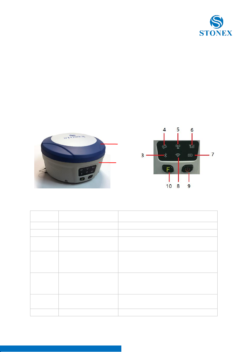
3. S9i mainframe.......................................................................................................................5
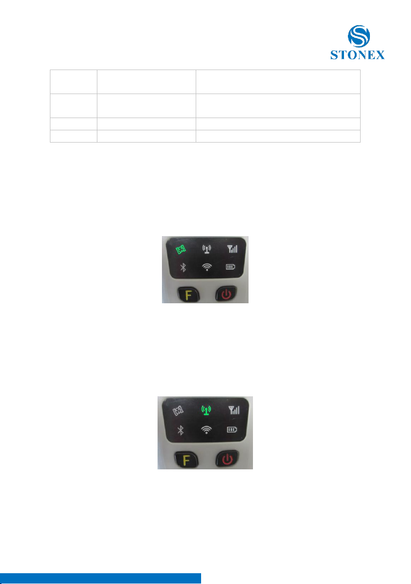
3.1. Front side of the mainframe ..................................................................................5
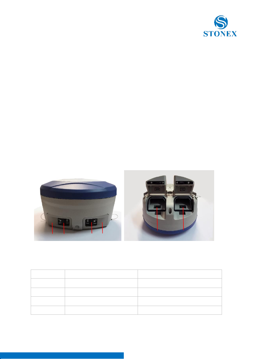
3.2 Back side of the mainframe.....................................................................................8
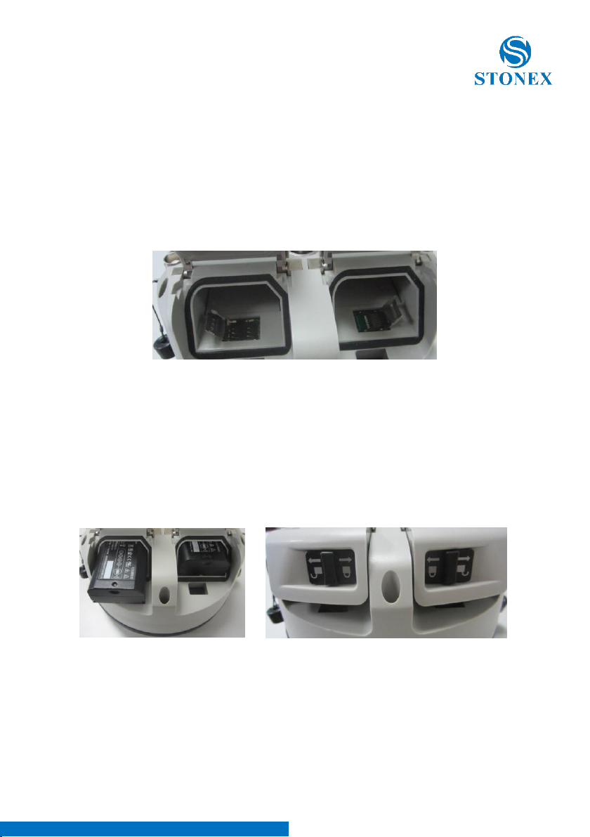
3.3 The bottom of mainframe..................................................................................... 10
4. Basic operations of S9i.................................................................................................. 11
4.1 The installation of base and rover.....................................................................11
4.2 The operation of keys .............................................................................................12
4.3 Switch work mode and datalink.........................................................................12
4.4 Self-checking ..............................................................................................................13
4.5 Measure the antenna height................................................................................ 14
5. Web UI function................................................................................................................ 15
5.1 Status .............................................................................................................................16
5.2 Information..................................................................................................................16
5.3 Download..................................................................................................................... 17
5.4 Management ..............................................................................................................17
5.4.1 Device register........................................................................................................ 19
5.5 Settings .........................................................................................................................19
5.5.1 Working mode ....................................................................................................... 20
5.5.2 Device configuration............................................................................................25
5.5.3. NMEA Message..................................................................................................... 26
6. S9i standard accessories............................................................................................... 27
6.1 The case of S9i...........................................................................................................27
6.2 Power supply ..............................................................................................................27
6.2.1 Batteries ....................................................................................................................27
6.2.2 Charger...................................................................................................................... 28
6.2.3 The antennas...........................................................................................................28
6.3 Cables ............................................................................................................................30
6.4 Other accessories...................................................................................................... 31
Appendixes...............................................................................................................................32
Appendix 1: Default radio configuration................................................................ 32
Appendix 2: Specification .............................................................................................33
Appendix 3: Copyrights, warranty and environmental recycling .................35
Appendix 4: Safety Recommendations................................................................... 42

Stonex S9iGNSS Receiver –User Manual 2
1. Introduction to Stonex S9iGNSS
This chapter is mainly used to introduce the key features and the appearance
of S9i.
S9i brings several technical news, like the new electronic bubble for levelling
or the double battery system for battery hot swap without powering off the
receiver .
If you are not familiar with GNSS technology, we suggest you to read a
specific book in order to understand in the best way the contents of this
manual. Anyway, you can ask for any technical support by sending an email
to our address support@stonex.it or contacting your local dealer.

Stonex S9iGNSS Receiver –User Manual 3
2. Key features
Designed and developed by a group of excellent developers, S9i has many
technical innovation.
All of the innovation are studied to complete the survey quickly and with
high efficiency. These main innovation be summarized in following 5 points:
(1) Electriconic bubble
S9i uses electronic bubble technology. The bubble is visualized on the
controller display. Thanks to the electronic bubble user doesn’t need to
check the liquid bubble ( mounted on the pole ) before to record a point
since point recording is allowed only when the pole is vertical.
(2) WIFI wireless connection
When WIFI function is active, S9i can be used like hotspot. You can connect
your phone to the receiver via WIFI. Using the WEB UI is possible to change
configurations of the receiver, like set the work mode (base-rover-static)
set the datalink (GSM-UHF-Bluetooth) or download record static data and
other.
(3) Dual mode Bluetooth
S9i supports Bluetooth technology, allowing connection to mobile phone,
windows mobile controller, digital consume products.
(4) Double backup of the survey data
S9i provide double back-up of data, both on the controller and on the
receiver (in raw format ) so to make the survey safe and reliable.
(5) Compatible with all satellite constellations
S9i can track all the available satellite constellation, GPS-Glonass-Beidou-
Galileo.
Additional technical innovation is the double battery system, allowing hot
swap without switching off the receiver.
In addition there are some other nice characteristics:

Stonex S9iGNSS Receiver –User Manual 4
(1) Compact and lightweight design.
The dimensions of S9i are: diameter 15.9cm × height 8.9cm. Weight is just
1.2kg. The compact and light weight design allow easy transport of it.
(2) Advanced datalink
The UHF radio module is compatible with the main RTK products in the
market and allow usage with other brand of RTK products. The 3.75G
modules support WCDMA and GPRS technology. It can continuously and
stably connect with reference stations.
(3) Innovation double high-capacity batteries
3400mAH high capacity battery. The double batteries design ensures long
worktime on field.
(4) 20HZ high-speed acquisition
S9i supports maximum 20HZ data rate acquisition.
(5) Large capacity storage
In addition to 4GB of internal memory, S9i also supports storage expansion
up to 32GB (by micro SD card).

Stonex S9iGNSS Receiver –User Manual 5
3. S9i mainframe
The mainframe of S9i is a flat cylindrical, 89mm in height, 159mm in
diameter. The front side has 2 functional buttons and 6 indicators. The back
side house the battery compartment. Here there are two slots, the first for
SIM card and the second for Micro SD card.
On the bottom of the receiver are located the UHF radio and GSM antenna
connector, a 5 pin external power interface and a 7 pin RS232/USB interface.
3.1. Front side of the mainframe
Figure 3 - 1 Front panel
Number
Name
Function
1
Top housing
Protect the antenna
2
Lower housing
Protect the receiver in case of drop.
3
Bluetooth led
It will be light when S9i is connected
via Bluetooth.
4
Satellite led
How many time it blinks, means how
many satellites are locked, cycle once
every 5 seconds.
5
Radio led
When the receiver is
transmitting/receiving radio signals, it
will blink.
6
Network led
It will blink when S9i is receiving
network signals from Cors
7
Power led
After the S9i turn on, the led always
1
2

Stonex S9iGNSS Receiver –User Manual 6
light and monitor the remaining
energy.
8
WIFI led
light when the S9i is connected with
WIFI.
9
Function key
Selection key
10
Power key
Power on/off the receiver.
Satellite led (green)
It shows the amount of locked satellites; when the receiver links one or more
satellites signals it will start to blink every 30 seconds for a number of times
equal to the number of locked satellites. When the receiver doesn’t lock
satellites, the satellite led does not shine.
Figure 3 - 2 Satellite led
UHF internal radio led (green)
This led is ON when UHF internal radio is selected as RTK datalink. It is
blinking when it is transmitting data in base mode or receiving data in rover
mode.
Figure 3 - 3 Internal radio led
Network led (green)

Stonex S9iGNSS Receiver –User Manual 7
This light is on when GSM/GPRS module is selected as RTK datalink. It starts
to blink when there is data transfer ongoing (download in rover mode and
upload in base mode).
Figure 3 - 4 Network led
Bluetooth led (blue)
Once you have connected the receiver to the handheld via Bluetooth, this led
will be on. This led is switched off Bluetooth is not connected .
Figure 3 - 5 Bluetooth led
WIFI led (green)
This led will on when you turn on the WIFI function. When you turn off the
WIFI function, this led does not shine.
Figure 3 - 6 WIFI led

Stonex S9iGNSS Receiver –User Manual 8
Internal power led (green and red)
When you power on the S9i, the power led will be on. According to the
remaining quantity of power in the battery, it monitor three kinds of status:
1. Green: power supply in good condition.
2. Red: low power (below 20%).
3. Red blinking and beeping: very low power (below 10%).
Note:
Usually when the light is red you have still one hour of power reserve.
External power and internal battery share same power light. When external
power is used, the led indicates the external power level. When the power is
below 10%, the red led will flash and you also hear three beeps every 60s.
3.2 Back side of the mainframe
Figure 3 - 7 S9i back side
Number
Name
Function
1
Battery compartment cover
Protect the battery
2
Compartment locker
Open/lock the cover
3
SIM card slot
Put and read SIM card
4
Micro SD card slot
Put and read Micro SD card
1
1
2
2
3
4

Stonex S9iGNSS Receiver –User Manual 9
Installing/Uninstalling SIM card and microSD card
To install the SIM card, push the SIM card holder left. With the SIM card’s
chip side facing down put the card into the slot. Close the holder then. The
microSD card installation is similar to the SIM card installation.
To remove the SIM card and microSD card, push the holder and then take
out the card.
Note: When you select network mode to work, you need to install SIM card.
Figure 3 - 8 Installing/uninstalling SIM/microSD card
Installing/Uninstalling battery
To install the battery, push the compartment locker, insert the battery into
the battery compartment, then lock the compartment locker.
To remove the battery, push the compartment locker and then take out the
battery.
Figure 3 - 9 Installing/uninstalling the battery

Stonex S9iGNSS Receiver –User Manual 10
3.3 The bottom of mainframe
Figure 3 - 10 S9i bottom
Figure 3 - 11 5-PIN interface Figure 3 - 12 7-PIN interface
Number
Name
Function
1
Network antenna interface
Connect to network antenna
2
Radio antenna interface
Connect to radio antenna
3
5 pin interface
Connect to external radio and
external battery
4
7 pin interface
USB port, also can connect to the
controller via the multi-function
cable
5
Beeper
Broadcast voice message

Stonex S9iGNSS Receiver –User Manual 11
4. Basic operations of S9i
In this section, we highlight the basic operations of S9i like setting for base
and rover, the operation of functional key , how to change the work mode
and datalink, how to start self-test procedure.
4.1 The installation of base and rover
The installation of base
1. Install the tripod on the chosen position, level it and attach the receiver
into tribrach.
2. Attach the transmitting radio antenna into the “UHF” connector. If you are
using a direct GSM connection, you should attach the GSM antenna into
“UMTS” connector.
3. Switch on the receiver and select the base working mode. If it is not
correct, please see next paragraph 2.3 for understanding how to select the
correct working mode or you can change it later using the handheld survey
software.
4. Switch on the handheld and start the software for the selected datalink
configuration. It is possible to make the settings also by Web UI function.
The installation of rover
1. Fix the bracket on the pole, fix the handheld to the bracket, put the rover
on the pole and attach receiving antenna into the port “UHF” or GSM
antenna into the port “UMTS”, depending on the connection used.
2. Power on the receiver and select the rover working mode. If it is not
correct, please see next paragraph 2.3 for understanding how to select the
correct working mode or you can change it later using the handheld
software.
3. Switch on the handheld and start the survey software.
Note: If you want to take very accurate measures (around or below cm
accuracy), we recommend you to use a tripod also for the rover.

Stonex S9iGNSS Receiver –User Manual 12
4.2 The operation of keys
There are 1 power key and 1 function key in the mainframe; the operations
are as follows.
Power key
The main function of power key is power on/off and “confirm button”.
- Power on: when the mainframe is in the OFF status (no light), press the
power key, and then the mainframe will enter the initialization status. Then
you will hear 3 beeps and an audio feedback (if enabled) reporting the
current receiver status .
- Power off: when the S9i mainframe is in the ON status (power supply light
ON), press and hold power key for few seconds until all lights blink, then
release the power key. An audio feedback report “If you want to turn off the
device”. Press the power key to confirm and S9i will be turned off.
F key: Function key
It could switch the working mode (static, base or rover) and RTK datalink
(built-in radio, external and network). Press the F key lightly, it will broadcast
the current receiver status.
4.3 Switch work mode and datalink
It is possible to switch work mode and datalink via the receiver or via
controller running survey software. Switch desired work mode first (it
includes base, rover, and static). Then select the datalink (GSM- internal UHF-
External UHF radio)
1. Keep press the F key and Power key until all lights blinking at the same
time, then the mainframe will voice broadcast to select work mode. Release F
and power keys and then press the F key to select the wanted working
mode: every time you press the F key, the mode will switch to another mode
(static, base and rover). Press the power key to confirm the selection
2. After setting work mode, the mainframe will voice broadcast to select the
datalink. Press the F key to select the datalink: every time you press the F key,
it will switch to one of three datalink modes (radio, external and network).
When the receiver switch to the datalink mode you want, press the power
key to confirm.

Stonex S9iGNSS Receiver –User Manual 13
3. Then the mainframe will voice broadcast “set WIFI”. Press the F key gently,
then there will be a voice broadcast “WIFI enable” or “WIFI disable”. Press the
power key to confirm, and there will be a voice broadcast “set successfully”.
4. Finally, press the F key gently, voice broadcast the mainframe current
working mode and datalink status.
Note: It is possible to switch work mode and datalink using Web UI function.
4.4 Self-checking
If the indicators are abnormal or the receiver can’t work normally, for
example if the Bluetooth can’t be connected or the radio mode does not
work you can use the automatic self-checking functions to detect the failure.
Self-checking will check GPS, radio, GSM, Bluetooth, WIFI and sensor. This
process has voice guide reporting the status of the module.
1. When the receiver is in powered on status, press and keep the power key
until a voice broadcast “if you want to turn off the device”, then release the
power key. Keep press the power key again until you hear a beep . Now a
voice broadcast “start self-checking” , release the power key and self check
will start .
2. In the process of device self-checking, there will be voice broadcast the
test results. If the module checking is successful, voice broadcast “success”
and the led always on until the self-checking is completed. If the module
checking fails, voice broadcast “self-checking fails”, the led will continue blink
and the buzzer beeps until you restart S9i. Self-checking procedure require
about 1 minute.
3. If all module leds are ON (not blinking) and voice broadcast that the self-
checking success (for example “self-checking GPS success”), it means the
modules could work normally.
Note: After self-checking, built-in radio frequency will return to factory
settings. If necessary, please contact your local dealer to change the
frequency to match your usage.

Stonex S9iGNSS Receiver –User Manual 14
4.5 Measure the antenna height
Figure 4 - 1 Altimetry line
Base and Static mode antenna height measurement
The main used method of antenna height measurement are :
Slant Height : You can measure from the ground to the altimetry line of the
mainframe,
Antenna vertical height : standard measure from the ground (known point)
to bottom of receiver.
Rover mode antenna height measurement
Measure methods of rover mode includes pole height, straight height and
slant height.
(1) Pole height, the height of the carbon pole, we can read it from the pole,
then input to the software.
(2) Straight height, including the antenna phase center height. Straight
height = the height from ground to bottom of mainframe + antenna phase
center to the bottom of mainframe.
(3) Slant height, measure from ground to the altimetry line of the mainframe.
Select slant height in the software, then input the height you measured.

Stonex S9iGNSS Receiver –User Manual 15
5. Web UI function
S9I has WIFI function that works as a hotspot with Phone, controller, PC and
other devices The default WIFI name is device number, there is no password
for WIFI.
Before using this function, you should make sure the WIFI function is
available. If the WIFI led is ON, it means the WIFI function is enable. If the
WIFI led is OFF, you should open the WIFI function first (refer to the
paragraph 2.3 to open the WIFI function).
After you open the S9i WIFI function, you could search the hotspot via
phone/PC/controller. The hotspot name is the S9i serial number (This WIFI
don’t have the internet access, you could just login the web page to view the
receiver status and set modes).
After connecting the WIFI, input IP “192.168.10.1” into your web browser to
open. Then it will pop up a window. It ask for log account and password,
default is:
Account: admin
Password: password
The Web UI contains Status, Information, Download, Management, and
Settings. It also can show the device number in the web.

Stonex S9iGNSS Receiver –User Manual 16
5.1 Status
In Status, you can see the current work status of the receiver, some basic
information. Such as system mode, current datalink, coordinate, satellites,
solution and so on. The detailed information you can see from the picture.
Figure 5 - 1 Status
5.2 Information
Then it’s the “Information”, this menu shows the information inside the
receiver, such as firmware version of the receiver, GNSS firmware version,
GSM mode information, sensor version, battery information and so on.
Figure 5 - 1 Information

Stonex S9iGNSS Receiver –User Manual 17
5.3 Download
“Download” is for downloading raw or rinex data files. The format of raw
data is “.dat”.
Figure 5 - 2 Download
5.4 Management
“Manage” includes many useful functions like upgrade firmware, register the
receiver, start self-checking, change the log password and restart the
receiver.

Stonex S9iGNSS Receiver –User Manual 18
Figure 5 - 3 Management

Stonex S9iGNSS Receiver –User Manual 19
5.4.1 Device register
The register code is a 32 digits and letters, you could register the device via
WEB UI function. The detailed steps as follow.
In management page, you could see “registration”. Input register code to
“Authcode” then click submit, the receiver will be registered.
Figure 5 - 5 Registration
You could also register device via controller with surpad software if installed
on your controller . Connect S9i with the surpad software . Click “About”, you
will see “Register instrument”, then click it. The last step is inputting code,
then finish registration.
5.5 Settings
“Settings” includes “Working Mode”, “Device Configuration” and “NMEA
Message”. Here will introduce every selection.
Table of contents
Other STONEX Receiver manuals

STONEX
STONEX S9III Plus User manual

STONEX
STONEX S900 User manual

STONEX
STONEX S900+ User manual

STONEX
STONEX S900T User manual

STONEX
STONEX SC600 User manual

STONEX
STONEX S990A User manual

STONEX
STONEX SC2000 User manual

STONEX
STONEX S580 User manual

STONEX
STONEX S980A User manual

STONEX
STONEX SC2200 User manual