STONEX S9III Plus User manual

Author: AM-Ver.1-Rev.4 CS (12/04/2014)
User Manual
STONEX S9III Plus
GNSS Receiver
www.stonexpositioning.com

Stonex S9III Plus GNSS Receiver –User Manual 1
Contents
1. A brief introduction of S9 III PLUS ........................................................................... 3
2. S9III PLUS mainframe ................................................................................................ 5
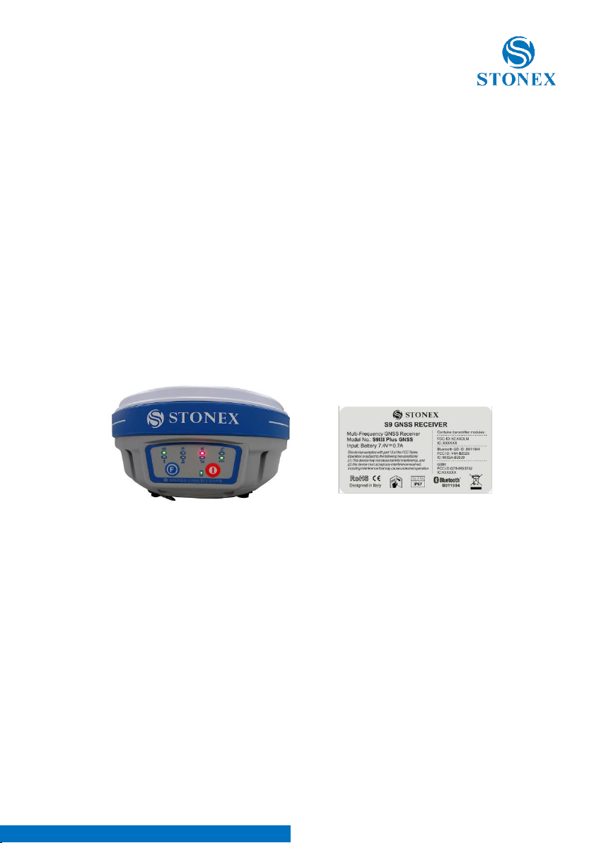
2.1. The outlook of mainframe..................................................................................................... 5
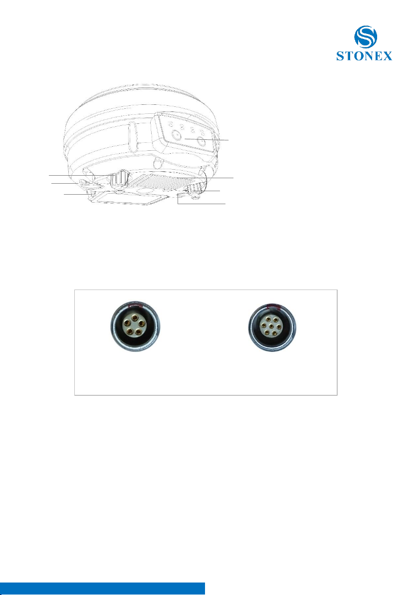
2.2. Interfaces..................................................................................................................................... 5
2.3. The battery housing................................................................................................................. 7
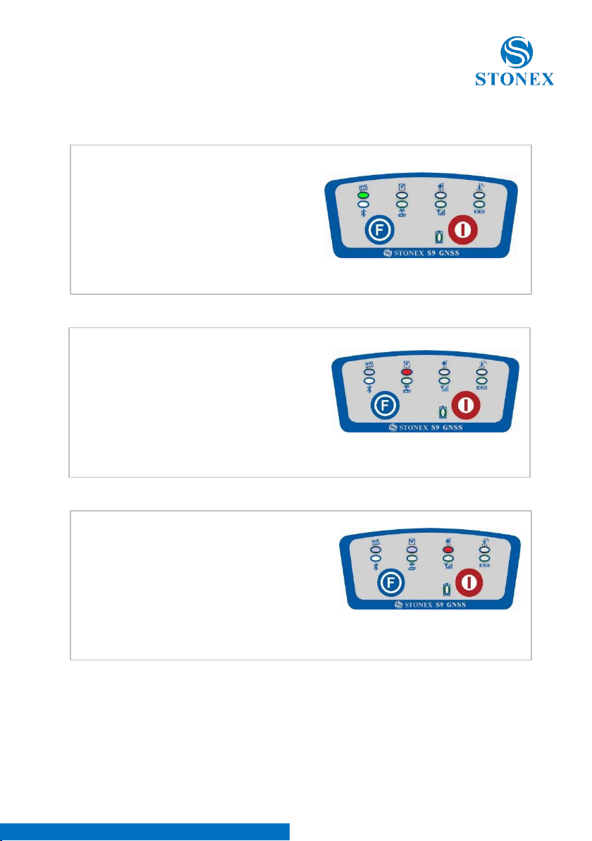
2.4. Indicator leds and instrument setup .................................................................................. 7
3. S9III PLUS standard accessories..............................................................................15
3.1.The case of S9III PLUS ............................................................................................................15
3.2. Power supply............................................................................................................................16
3.3. The antennas............................................................................................................................17
3.4. Cables.........................................................................................................................................19
3.5. Other accessories....................................................................................................................19
3.6. Controllers.................................................................................................................................22
4. S9III PLUS Configuration .........................................................................................23
4.1. The installation of base and rover.....................................................................................23
4.2. Standard operation of leds..................................................................................................24
4.3. How to measure the antenna height ...............................................................................25
5. STONEX® Assistant for S9III PLUS.........................................................................27
5.1. Start Stonex Assistant on your PC.....................................................................................27
5.2. Settings ......................................................................................................................................30
5.2.1. Static Data Survey ...............................................................................................................31
5.2.2. Dynamic..................................................................................................................................32
5.2.2.1. Base coordinates setting ...............................................................................................33
5.2.3. Data Link ................................................................................................................................35
5.2.3.1. Network...............................................................................................................................35
5.2.3.2. UHF Radio ..........................................................................................................................40
5.2.3.3. External................................................................................................................................41
5.2.3.4. Bluetooth............................................................................................................................42
5.2.3.5. No Datalink –only for Rover........................................................................................42
5.2.3.6. Network and External - only for Base........................................................................43
5.2.4. NMEA Output string...........................................................................................................43
5.3. Import Data ..............................................................................................................................45
5.4. Serial Port Forwarding...........................................................................................................46
5.5. Register......................................................................................................................................50
5.6. Firmware update.....................................................................................................................52
6. Appendices................................................................................................................55
Appendix 1: Default Radio Settings..........................................................................................55
Appendix 2: Technical Specifications .......................................................................................56
Appendix 3: Safety Recommendations....................................................................................59
Warnings and Cautions ................................................................................................................59
Wireless Module Approval ..........................................................................................................59

Stonex S9III Plus GNSS Receiver –User Manual 2
Instrument Approval......................................................................................................................60
Pacific Crest XDL Micro UHF 410-470 MHz Data transceiver...........................................60
Appendix 4: Copyrights, warranty and environmental recycling ....................................65

Stonex S9III Plus GNSS Receiver –User Manual 3
1. A brief introduction of S9III PLUS
STONEX® devoted itself to offer to surveyors the most advanced GPS tools.
GPS RTK surveying technology plays an important role in surveying tasks and
its use is getting more and more widespread.
As a leading GPS RTK instrument producer, STONEX® guarantees that the
S9III PLUS, our new RTK GPS receiver, is suited for nowadays demands of
precision, reliability and user friendliness.
S9III PLUS is a multi-constellation GNSS receiver, able to receive three GPS
signal frequencies, GLONASS and Compass/Beidou, ready for GALILEO
constellation.
S9III PLUS mainframe integrates a GNSS antenna, GNSS module, UHF
transmitting and receiving radio, radio antenna, GSM/GPRS modem,
Bluetooth device and battery.
So S9III PLUS is totally integrated: it means that the surveyor only needs the
handheld to start its job.
The exquisite outlook and the amazing color bring you a fashioned surveying
station. This device has a higher stability, lesser power consumption, smaller
volume and lighter weight than the previous STONEX® receivers.
S9III PLUS has a special design which makes it waterproof, dustproof and
vibration-proof. The batteries and built-in radio are set in the bottom of
mainframe, giving more effective dustproof and waterproof qualities and
makes the S9III PLUS a better performer in field of surveying. The Wireless
receiver unit (weighs) 1.2 kg: the rover is light and easy to carry. The low power
consumption of receiver allows users to carry out and work in long time with
only one single battery.
Integrated design and anti-jamming property are combined perfectly: the
former avoids the problem of a cumbersome external antenna, and the
mainframe design can resolve the jamming problem effectively.
The S9III PLUS receiver mounts a GPS/GLONASS/BD antenna with a four feed
technology.
This design is able to reduce the electrical phase center error ellipsoid and in
addiction it improves the Right Hand Circular Polarization Characteristics
(RHCP) of the antenna, resulting in enhanced GPS signal tracking and
improved multipath rejection, in case a polarization reversal has taken place
as a result of the signal reflection.
S9III PLUS has a new 3G GPRS/GSM module which allow faster and more
reliable connections.

Stonex S9III Plus GNSS Receiver –User Manual 4
This allows STONEX® S9III PLUS receiver to be a flexible system for
demanding surveying applications. As a rover, it can be used as a static double
frequency receiver or in a RTK configuration, where differential corrections are
received from CORS via GSM/GPRS data modem (maximum range 70 km) or
by another S9III PLUS receiver acting as base, linked by GSM/GPRS data
modem or UHF radio modem.
In the last case S9III PLUS in base configuration can transmit with the built-in
0.5/2 W radio or can be connected to a more powerful external radio at user's
disposal in order to reach the requested metric range.
The receiver can be connected to different RTK software for different
applications. The data transfer is easy and fast, like a Plug and Play USB drive.
STONEX® provides two year of warranty to S9III PLUS receivers.
It should be noted that high power signals from a nearby radio or radar
transmitter can overwhelm the receiver circuits. Low power transmitter like
those used in cell-phones do not normally interfere with receiver’s operations.
It’s important to draw your attention to the operational temperatures, limits
which should not be exceeded for a correct functioning (see pag. 65).
It is also important to point out that in each weather case after coming back
from the field you should keep the container open in a warm and dry place
and at the same time take out the controller and receiver from the container,
in order to make them dry.
Anyway we recommend you to manage the instrument with reasonable care.
Even if you have used other GPS or GNSS products before, we recommend
that you spend some time reading this manual to learn about the special
features of this product.
If you are not familiar with GNSS technology, we suggest you read a specific
book in order to better understand the contents of this manual. Any way you
can ask for any technical support by sending an email to our address
ATTENTION:
This manual is valid for both S9 III PLUS and S9 III N PLUS. Their constructions,
functions and operations are the same, just the second model is built without
internal UHF radio, so you have just to ignore every information referred to
the radio.

Stonex S9III Plus GNSS Receiver –User Manual 5
2. S9III PLUS mainframe
2.1. The outlook of mainframe
The mainframe has an almost cylindrical shape, with a base larger than the
height. There are three parts: an upper cap, a rubber loop and the main
structure. The upper cap protects the GNSS antenna placed inside.
The rubber loop has the function of softening possible shocks or falls. In the
front of the main structure there are 2 keys and 9 lights, on the bottom side
there is one slot for the built-in radio and GSM/GPRS module, and one for the
battery and SIM card.
All the others components of the receiver (Bluetooth device, main board, OEM
board, etc.) are contained inside the main structure.
2.2. Interfaces
The mainframe interfaces are shown in Fig. 2.3: the left port (five pins LEMO)
is used for external power supply and external radio connection, the right port
(seven pins LEMO) is used for data transferring between receiver and
computer or between receiver and the handheld. Near the radio and
GSM/GPRS module there are radio and GSM/GPRS antenna interfaces.
Fig. 2.1 - S9III PLUS mainframe
Fig. 2.2 - S9III PLUS label

Stonex S9III Plus GNSS Receiver –User Manual 6
Fig. 2.4 - 5-pins LEMO port Fig. 2.5 - 7-pins LEMO port
Fig. 2.3 - S9III PLUS components and ports
d
e
g
a) TNC connector for GPRS/GSM
antenna
b) 5pins Lemo port for external
datalink connection
c) Battery housing
d) Front panel
e) Built-in radio and GSM/GPRS
module
f) 7pins Lemo port for data transport.
g) TNC connector for UHF radio
antenna
b
a
c
f

Stonex S9III Plus GNSS Receiver –User Manual 7
2.3. The battery housing
1. SIM card slot
2. MicroSD card slot
3. Battery
4. Battery cover
Under the place for the battery, there is the slot for SIM card and SD memory
card.
2.4. Indicator leds and instrument setup
Fig. 2.6 - S9III PLUS battery housing
1. satellite led
2. static led
3. rover led
4. base led
5. Bluetooth led
6. UHF internal radio led
7. GSM/GPRS led
8. External data link led
9. Power supply led
10. Function Key
11. Power Key
Fig. 2.7 - S9III PLUS keys and indicator leds
1
2
3
4

Stonex S9III Plus GNSS Receiver –User Manual 8
The functionality as follows, from left to right:
SATELLITE led (green):
It shows the amount of locked satellites;
when the receiver links one or more
satellites signal it will start to blink every
30 seconds for a number of times equal to
the number of locked satellites.
STATIC led (red):
It switches on if the static mode is selected
and it starts to blink when the receiver is
recording data, with the same frequency
of the sample rate.
ROVER led (red):
Rover led is on when the receiver is working
in rover mode.
Fig. 2.8 - S9III PLUS satellite led
Fig. 2.9 - S9III PLUS static led
Fig. 2.10 - S9III PLUS rover led

Stonex S9III Plus GNSS Receiver –User Manual 9
BASE led (red):
Base led is on when the receiver is working
in base mode.
BLUETOOTH led (blue):
Once you have connected the receiver with
the handheld, this led will on.
UHF INTERNAL RADIO led (green):
This led is ON when UHF internal radio is
selected as RTK datalink.
It is blinking when it is transmitting data in
base mode or receiving data in rover mode.
Fig. 2.11 - S9III PLUS base led
Fig 2.12 - S9III PLUS Bluetooth led
Fig 2.13 - S9III PLUS internal radio led

Stonex S9III Plus GNSS Receiver –User Manual 10
GSM/GPRS led (green):
This led is on when GSM/GPRS module is
selected as RTK datalink. It starts to blink
when there is data transfer ongoing
(download in rover mode and upload in
base mode).
EXTERNAL DATALINK led (green):
This led is on when external datalink
(external radio, external Bluetooth device,
etc.) is selected as RTK datalink. It starts to
blink when there is data transfer ongoing
(download in rover mode and upload in
base mode).
INTERNAL POWER led (green and red):
It includes two kind of status:
1. Green: power supply in good condition.
2. Red: low power (below 20%).
3. Red blinking and beeping: very low power
(below 10%).
Usually when the led is red you have still one hour of power reserve. External
power and internal battery share same power light. When external power is
used, the led indicates external power level. When the power is below 10%,
the red led will flash and you also hear three beep every 60s.
Fig. 2.16 - S9III PLUS power led
Fig 2.14 - S9III PLUS internal radio led
Fig 2.15 - S9III PLUS external radio led

Stonex S9III Plus GNSS Receiver –User Manual 11
F Key: Function key
It can switch the working mode (static, base or rover) and RTK datalink (built-
in radio, external datalink or GPRS/GSM).
Switch working mode: Power on the receiver while pressing F key in the
meantime, wait until all lights flash, then release both buttons. Now every time
you press F key, you will see one red led switched on and moving through the
three working mode from left to the right.
Switch datalink: Press F key in ROVER or BASE mode, you will see one green
led switched on, that moves every time you press F key through the three
datalink from left to right.
I Key: Power key
It turns on/off the receiver and has also a confirm function.
Power on receiver: Press and hold I key for at least one second, the receiver
will power on.
Power off receiver: Press and hold I key for few seconds, after three beeps all
lights turn off, at that point release the key, the receiver is off .
Self-Check
It is a procedure predisposed for verifying the correct working of the
instrument devices, the operation way is:
-Press and hold I key for more than 10 seconds, as for turning it off,
but keeping pressed the key after all lights have turned off.
-Release the key when you hear another beep: receiver is starting to
make a self-check.
Self-check lasts typically around 1 minute. During this procedure some leds
will turn on in a sequence, the meaning of lights is:
-Internal radio led: ON if UHF module pass the test; it flashes if
UFH module fails the test.
-GSM/GPRS led: ON if GSM/GPRS module pass the test; it flashes
if GSM/GPRS module fails the test.
-Satellite led: ON if GNSS OEM module pass the test; it flashes if
GNSS OEM module fails the test.
If you have noticed at least one problem during self-check, please contact your
local dealer or email to support@stonex.it.

Stonex S9III Plus GNSS Receiver –User Manual 12
After the self-check procedure, the receiver will turn on and begin to work
normally.
How can you select the working mode?
-Insert the battery, then press and hold I key + F key: the receiver
will start.
-Keep pressed I key + F key until the all lights blink at the same
time (Fig. 2.17), then release the keys.
-Now every time you press F key, the STATIC/ROVER/BASE lights
will turn on in the corresponding order. You can select three
different red lights, each of them refers to one working mode.
Press I key when the chosen light is on and the receiver will restart into the
selected working mode. Summary of working modes:
Fig. 2.18 - S9III PLUS summary of working mode led
1. Static mode
2. Rover mode
3. Base mode
Fig. 2.17 - S9III PLUS, all led blinking at the same time
1
2
3

Stonex S9III Plus GNSS Receiver –User Manual 13
Some definitions of working mode:
Static:is the stand-alone station that collect raw observations and need a post-
processing in office for getting accurate results.
Base: is the fixed GPS station used to provide differential corrections to the
mobile GPS receiver.
Rover: is the mobile receiver used to survey on field.
How can you select data link?
-After you have entered working mode, press F key, the
UHF/GPRS/EXT lights will blink by turns. Then you can select different
green lights, each one refers to different data link. This situation
refers only to the rover and base mode, since in static mode there is
no green light blinking.
-Press I key when the chosen light is blinking and the receiver will start
in the selected working mode. Summary of data link types:
Summary of data link types:
Some definitions of available datalink:
Network: is an internet connection by GPRS band to a base that provide
differential corrections or a connection between base and rover by a GSM
direct call (like a phone call).
4. Internal UHF Radio
5. GPRS\GSM module
6. External radio
Fig. 2.19 - S9III PLUS summary of data-link led
4
5
6
4. Internal UHF
5. GPRS/GSM module
6. External radio
5
4

Stonex S9III Plus GNSS Receiver –User Manual 14
UHF: is a connection between base and rover by the internal radio
communication.
External: is a connection between base and rover by an external device
attached through the 5-pin LEMO port, it is usually an external radio.
Bluetooth: is an option for sending or receiving the NTRIP corrections to the
receiver through the Bluetooth channel.
Note: To select or to change working mode or datalink is also possible both
by Stonex Assistant (see chapter V) or by field software.

Stonex S9III Plus GNSS Receiver –User Manual 15
3. S9III PLUS standard accessories
On the basis of the configuration chosen (base or rover) some of these
accessories are included in the receiver bundle.
3.1. The case of S9III PLUS
There are two kinds of S9III PLUS cases: Rover case and Base case. The inner
layout of the Base case and Rover case is different.
Base case has the room for external radio and Rover case has the room for the
controller. You can distinguish them from nameplate.
Fig. 3.1 - S9III PLUS case
Fig. 3.2 - S9III PLUS Rover case
Fig. 3.3 - S9III PLUS Base case

Stonex S9III Plus GNSS Receiver –User Manual 16
3.2. Power supply
Batteries
The standard configuration contains two batteries, a slot for charging batteries
(named “charger” for simplicity) and an adaptor. The battery are “lithium-ion”
battery (7.4V - 2500 mAh): a technology which has an higher energy-to-weight
ratio with respect to NiCd or NiMh batteries, no memory effect, and slow self-
discharge when not in use.
Fig. 3.4 - S9III PLUS internal case of Rover

Stonex S9III Plus GNSS Receiver –User Manual 17
Charger
The charger can charge both batteries simultaneously. The lights of the
charger shows if the battery is being charged (red light CHARGE) or if it’s
already charged (green light FULL). Red light POWER shows if the charger is
powered on and there is also a light which turns on in case of too high
temperature (red light TEMP).
3.3. The antennas
S9III PLUS adopts a UHF all-direction transmitting and receiving antenna.
There are three different internal radio settings with different frequency range.
The available range are: 410-430 MHz, 430-450 MHz and 450-470 MHz. They
are suitable for field surveying, light and durable. The gain is 4 dBi, it was
recently improved with respect to the old model that was 2.15 dBi, leading to
an increase of the range.
Fig. 3.5 - Lithium-ion battery
Fig. 3.6 - S9III PLUS charger and adaptor

Stonex S9III Plus GNSS Receiver –User Manual 18
S9III PLUS adopts a GPRS/GSM all-direction transmitting and receiving
antenna with a frequency in the ranges 824-960 MHz and 1710-2170MHz. It
is suitable for field surveying, light and durable, the length is about 21.5 cm,
the gain is around 1.8-2.2/2.1-3 dBi.
For S9III PLUS, it is possible to use like additional accessory (not included in
the standard configuration) a high-gain UHF all-directional transmitting
antenna for base setup. The available ranges are: 410-430 MHz, 430-450 MHz
and 450-470 MHz. The antenna is around 1 meter long and can be mounted
on a retractable pole or a tripod for better performance. The higher the
antenna is, the larger cover area does it has for the radio signal. The gain of
the antenna is 5 dBi.
Fig. 3.9 –External radio antenna (not in scale)
Fig. 3.7 –built-in radio antenna (not in scale)
Fig. 3.8 –GPRS/CDMA2000/WCDMA antenna (not in scale)

Stonex S9III Plus GNSS Receiver –User Manual 19
3.4. Cables
Receivers cables (LM.GK205.ABL)
This is a multi-function communication cable: it is used for connecting receiver
and computer and, through Stonex Assistant, for transferring the static data,
updating the firmware and the license.
Fig. 3.10 - Multi-function communication cable
Auxiliary cables (LM.GK185.ABL+ LM.GK224.AAZ)
External power supply cables (LM.GK185.ABL+ LM.GK224.AAZ) can be ordered
and used to connect an external battery (red and black clips) to the receiver
(small 5-pin LEMO):
Fig. 3.11 - External power supply cables
3.5. Other accessories
The other accessories are: 2.45 m retractable pole, two kind of brackets
depending on the controller, tribrach with plummet, tripod (wood or
aluminum, with quick or twist clamps), connector between receiver and
tribrach, and measuring tape.
Table of contents
Other STONEX Receiver manuals