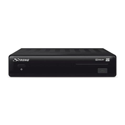
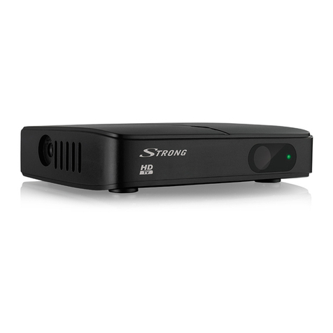
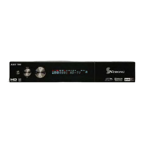
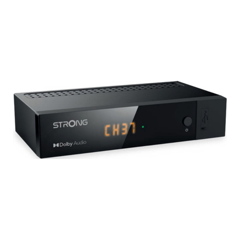
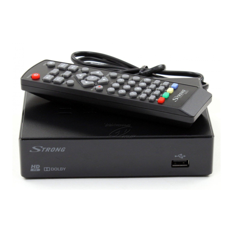
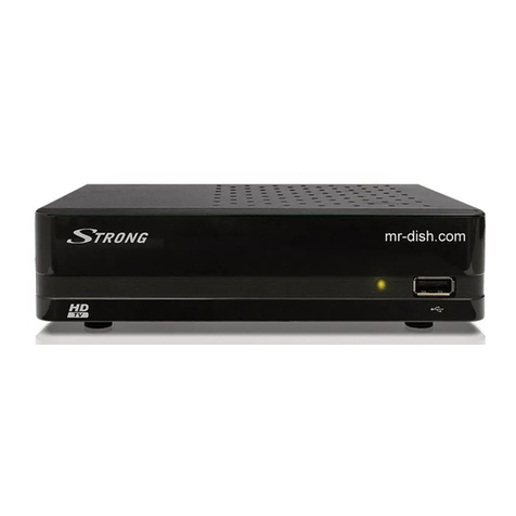
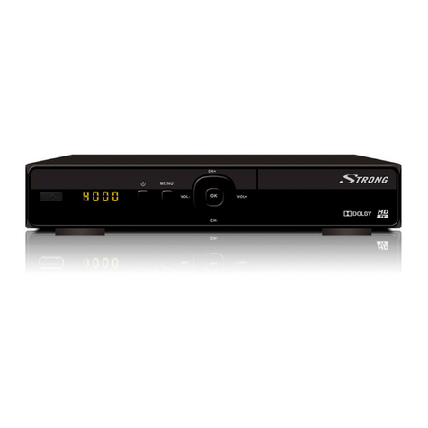
Strong SRT 5855 User manual


Table of Contents
1.0 Usage 3
1.1 Safety Instructions 4
1.2 Features & Accessories 5
1.3 Safety Precautions 6
1.4 Storage 7
1.5 Equipment Set-up 7
2.0 Your DVB-T Receiver 8
2.1 Front Panel 8
2.2 Rear Panel 8
2.3 Basic Functions Remote Control 10
3.0 Connections 12
3.1 Connecting to your TV & VCR 12
3.1.1 Basic connection with a coaxial cable 12
3.1.2 Basic connection with a Scart cable 12
3.1.3 Advanced connection 12
3.1.4 Connection with Audio Cable RCA Connectors 13
3.1.5 Connection to a digital audio amplifier using
the S/PDIF output 13
3.1.6 Connecting a remote eye (optional accessory) 13
3.1.7 Connecting a serial cable for downloading software 14
4.0 Starting up 14
4.1 Starting up for the First Time 14
5.0 Basic settings 15
5.1.1 Main Menu 15
5.1.2 Channel Organizer Menu 15
5.1.3 The Timer Menu 16
5.1.4 The Installation Menu 18
5.1.4.1 System Set-up Menu 18
5.1.4.2 Channel Set-up 22
5.1.4.3 Parental Lock – Changing PIN Code 23
6.0 Pay TV – Subscription 25
6.1 Putting your card into the receiver 25
6.2 Activating the card 25
A1 Troubleshooting 26
A2 Glossary of terms 28
A3 Technical specification 30
2

3
Thank you for choosing this Strong Digital Terrestrial Television Receiver. This receiver is
of our latest development and it is designed to be capable of upgrading its software
through the PC. It is highly recommended that you read this manual carefully to safely
install your receiver and to achieve its optimum performance.
1.0 Usage
This user manual is applicable for Strong SRT 5855 Digital Terrestrial Receiver and its
related accessories. It is advised that first time and experienced users read this manual in
order to safely install the receiver.
Strong has supplied this product with the most recent innovations of software and
hardware. Strong reserves the right to make changes in production to the software used
by your terrestrial receiver without prior notification. In order to maintain and ensure that
your receiver is compatible and updated with the most recent software technology, we
recommend that you visit our website to check the latest software. (www.strongsat.com)

1.1 Safety Instructions
Warning:
DO NOT INSTALL YOUR RECEIVER:
In a closed or poorly ventilated cabinet;
Directly on top of or under any another equipment;
On a surface which might obstruct the ventilation slots.
DO NOT EXPOSE THE RECEIVER OR ITS ACCESSORIES:
To direct sunlight or near any other equipment that generates heat;
To rain or intense moisture.
To any shock which may cause permanent damage to your receiver;
To any magnetic objects, such as loudspeakers, transformers, etc.;
To intense vibration.
Never open the cover. It is dangerous to touch the inside of the receiver due to
high voltage currents and possible electrical hazards. Your warranty will be void
if the receiver has been opened.
When the receiver is not used for a long period of time, you should unplug the
power cord from the wall socket.
Do not use a damaged power cord. It may cause a fire or an electrical shock.
Do not touch a power cord with wet hands. It may cause an electric shock.
Place the receiver in a well-ventilated environment.
When you are connecting the cables, be sure that the receiver is disconnected
from the mains supply voltage.
Do not use your receiver in a humid environment.
4

5
Make sure you read this user manual before installing your receiver.
This manual provides complete instructions for installing and using this receiver. The
following symbols will be used as follows:
Bold Characters: Represents a button on the remote control or the receiver.
Italic Characters: Represents a menu item within the On Screen Display
(OSD) Menu.
1.2 Features & Accessories
SRT 5855 Digital Terrestrial Receiver:
Easy to use Graphic MENU Interface
Automatic channel scan
2 TV SCART Connectors (VCR and TV)
3 RCA Connectors (CVBS, Audio Left/Right)
Multi-Language function (Menu, Audio)
IR sensor-connector for connecting an external remote eye to control the receiver
(available as accessory)
Front Panel Buttons & standard remote control
EPG (Electronic Program Guide) for on screen channel information
Over 250 channels memory capacity
2 Operation Modes (Digital TV, Digital Radio)
Digital Tuner with Loop-through output
MPEG-2 Main Profile at Main Level
Supports software downloading via PC — through RS 232 port for updating
software and additional services
S/PDIF output for connection with a digital audio amplifier
Built-in UHF modulator

For all digital Free-To-Air TV and Radio programmes via your TV antenna (no
satellite or cable connection needed)
Single Smart Card reader for Pay TV services (Conditional Access
for Mediaguard)
Accessories:
User’s Manual
Standard remote control unit
2x Batteries (AAA type)
Scart cable
Optional Accessories:
Remote Eye
Note: The batteries should not be recharged, disassembled, electrically short-circuited or
be mixed or used with other types of batteries.
1.3 Safety Precautions
To maintain your receiver’s optimum performance, you are advised to apply the following
safety precautions:
Read this manual carefully and make sure you fully understand the instructions
given.
Refer all maintenance or servicing to suitably qualified personnel
If you wish, you may clean your receiver with a soft lint-free cloth slightly made
damp with a mild soap solution, only after disconnecting from the mains voltage
supply.
Do not use alcohol or ammonia based liquids to clean the receiver.
Do not open the receiver cover, as you will be exposed to a shock hazard
Do not open the receiver cover, this will void your warranty.
6

7
Do not place any objects on top of the receiver because this might prevent
proper cooling of the components inside.
Make sure no foreign objects fall through the ventilation slots because this could
cause fire or an electric shock.
Wait a few seconds after switching off the receiver before you move the receiver
or disconnect any equipment;
Please ensure that that the electrical power supply corresponds with the voltage
on the electrical identification plate at the back of the receiver.
It is a necessity that you only use an approved extension and compatible wiring
that is suitable for the electrical power consumption of the installed equipment.
If the receiver does not operate normally even after strictly following the
instructions in this user manual, it is recommended to consult your dealer.
1.4 Storage
Your receiver and its accessories are stored and delivered in protective packaging against
electric shocks and moisture. When unpacking it, make sure that all the parts are included
and keep packaging away from children. When transporting the receiver from one place to
another or if you are returning it under warranty make sure to store the receiver in its
original packaging with its accessories. Failing to comply with such packaging procedures
could void your warranty.
1.5 Equipment Set-up
We recommend you to consult a professional installer to set up your equipment.
Otherwise, please follow the following instructions:
Refer to the user manual of your TV and/or your antenna.
Make sure that the SCART cable is in a good condition.
Make sure that the SCART cable connections are well shielded
Make sure that the outdoor components of the antenna are suitable for Digital
Terrestrial reception and that you are in a coverage area. More information
available from; FREEVIEW on 08708 809980; Top Up TV on 08700 543210 or
“Text” your postcode to 83331 (standard rates apply)
2.0 Your DVB-T Receiver
2.1 Front Panel (Please see inside cover Figure 1)
1. Power Button
Turns the receiver ON/OFF.
2. The 3 LED’s
Indicate; Stand-BY, ON and SIGNAL “locked”. The red LED is the “stand-by”
indicator. The green LED is the “Power On” indicator. The orange LED lights up
once you correctly receive an antenna signal (signal locked)
3. UP/DOWN Buttons
Changes the channels UP/DOWN in no menu state.
4. Card Reader
Insert your Pay TV subscriber card here.
2.2 Rear Panel (Please see inside cover Figure 2)
1. ANTENNA INPUT
Connect the antenna cable to this connector.
2. RF OUTPUT
Gives you the possibility to connect the receiver to TV by RF cable.
8

9
3. AUDIO Right and Left (Red &White RCA)
These connectors give you the possibility to connect the audio signal to an external
amplifier or to the audio input of your TV.
4. VIDEO (Yellow RCA)
This connector has a constant video signal for additional VCR-connections.
5. TV Scart Connector
Use this connector to connect your receiver to your TV using a scart cable.
6. VIDEO Scart Connector
Use this connector to connect your receiver to your video recorder using a scart
cable. Your video signal will now be looped through to your TV.
7. IR SENSOR
Use this connector to connect an external remote eye if you wish to store your
receiver in a place where the IR on your receiver cannot communicate with the
remote. For example, if you wish to put your receiver in a closed environment such
as a well ventilated closet.
8. RS 232 Serial Port
This serial port can be used to connect your PC to your receiver, and enables you
to download new versions of software into your receiver.
Note: It is recommended to ONLY use the original software. Loading other versions of
software not adapted to your model number can cause severe damage to your
receiver, and will not be covered by the warranty.
9. S/PDIF
Use this coaxial output to connect your receiver to the input of your digital audio
amplifier.
10. Power Cord
Your receiver requires a main voltage supply of 220 V AC 50/60 Hz +/- 5%. Make
sure to check the power supply specifications of the wall outlet before connecting
your receiver to main power!

2.3 Basic functions remote control (Please see inside cover Figure 3)
All features of the set-top box can be controlled with the remote control. Inserting
batteries to the Remote Control Unit:
1. Open the battery cover on the rear of the remote control Unit.
2. Insert the two supplied batteries (1.5V) observing the polarity (+/-) and the
“AAA” specification.
3. Firmly replace the battery cover.
REMOTE KEY FUNCTIONS
1. STANDBY ON/OFF
Switches the Receiver ON or OFF.
2. SUB
Display subtitles of broadcast.
3. HELP
Unused – For future applications.
4. MUTE
Enables or disables the audio.
5. ARROW UP/DOWN
Moves cursor up or down for navigating within the OSD menu.
6. ARROW RIGHT/LEFT
Moves cursor to right or left for navigating within the OSD menu.
7. 7. SELECT/ OK (see inside cover screenshot 30)
Selects function highlighted in OSD.
8. “i” INFO
Selects channel information banner.
9. AV
Selects TV or Digital TV.
10. AUDIO
Displays audio track selection.
10

11
11. BACK
Navigates you back to the previous OSD menu.
12. TEXT
Enables Digital Text menu.
13. MENU
Selects the main OSD menu for setting the receiver.
14. VOL +/-
Used for adjusting the volume up or down.
15. CHANNEL UP/DOWN
Selects the next channel up or down.
16. BACK
Returns to TV mode from Text or Guide modes.
17. GUIDE
Displays the extended program guide.
18. “RED”
Navigation key for interactive services and menu modes.
19. “GREEN”
Navigation key for interactive services and menu modes.
20. “BLUE”
Navigation key for interactive services and menu modes.
21. “YELLOW”
Navigation key for interactive services and menu modes.
22. 0-9 Numeric Keys
Direct entry for channel selection and Text page entry.

3.0 Connections
3.1 Connecting to your TV & VCR
3.1.1 Basic connection with a coaxial cable (Please see inside cover Figure 4)
Connect the antenna cable of your terrestrial antenna with the ANT input.
Connect to RF OUT connector at the back of the receiver to the ANT IN
connector on your TV set.
3.1.2 Basic connection with a Scart cable (Please see inside cover
Figure 5)
Connect the antenna cable of your terrestrial antenna with the ANT input.
Connect the TV scart connector at the back of the receiver to the scart-in
connector on your TV set.
3.1.3 Advanced connection (Please see inside cover Figure 6)
Connect the antenna cable of your terrestrial antenna with the ANT input.
Connect the TV scart connector at the back of the receiver to the scart-in
connector on your TV set.
Connect the VCR scart connector at the back of the receiver to the scart-in
connector on your VCR set.
Connect a coaxial cable to the TV/VCR connector at the back of the receiver.
Connect the other end of this coaxial cable to the ANT IN connector of your
VCR.
Connect the TV OUT connector of your VCR to the ANT IN connector of your TV
set with a coaxial cable.
12

13
Note: If you have a digital audio amplifier with a digital audio input, use the
S/PDIF output.
3.1.4 Connection with Audio/Video RCA Cable (Please see inside cover Figure 7)
On the back of your receiver you will find the RCA connectors (Audio Left &
Right – Red& white, Video – Yellow)
Install an audio/video cable between the RCA connectors of the receiver and
those of your TV set, VCR or amplifier.
3.1.5 Connection to a digital audio amplifier using the S/PDIF output
(Please see inside cover Figure 8)
Connect the S/PDIF out connector on the back of your receiver to the S/PDIF
input connector of your digital amplifier, using a coaxial cable.
Do not forget to turn the S/PDIF function on (Main menu > Installation >PIN
code ”0000”> TV/VCR Settings > SPDIF Output > On)
3.1.6 Connecting a remote eye (Please see inside cover Figure 9)
Connect the IR sensor to your remote eye if you wish to store your receiver in a
place where the IR on your receiver cannot communicate with the remote.
For example, if you wish to put your receiver in a closed environment such as a well
ventilated closet.

3.1.7 Connecting a serial cable for downloading software
(Please see inside cover Figure 10)
Connect the RS 232 connector on the back of your receiver to the Serial port of
your computer using a serial cable.
4.0 Starting up
Ensure that your terrestrial receiver is correctly connected to your television and dish, and
that your antenna signal is of good quality. (If you are not sure about this then ask your
local Strong dealer to check your installation or antenna signal).
4.1 Starting up for the First Time
Connect your DVB-T receiver as described under one of the points in
paragraph 3.
Press “MENU” key (13);
Using the arrow up or down keys (5), move the cursor until the highlight colour
is over INSTALLATION; Press the SELECT key (7).
Using the arrow up or down keys (5), move the cursor until the highlight colour
is over CHANNELS SETUP; Press the SELECT key (7).
To select AUTOMATIC tuning, press the RED function key (18).
Wait a few minutes while the tuning automatically finds and loads all the
channels.When tuning has completed, press the BACK key (11)
to view the picture.
14

15
5.0 Basic settings
Note: Every time the receiver asks you to put your PIN code, enter ‘0000’ on your remote
control using [0-9] numeric keypads.
5.1.1 Main Menu (Please see inside cover Screen 1)
All the important settings and features of your receiver can be operated from the Main
Menu. The Main Menu consists of several sub-menus such as “Channel Organizer”,
“Timer”, “Installation”. To display and navigate through the main menu of the receiver
please apply the following steps:
1. Press the Menu button.
2. Use UP/DOWN keys, to navigate through the menu.
3. Press SELECT button every time you select an item from the menu.
4. Press the BACK button to terminate an operation.
5. Press the BACK button until you go back to main menu.
Tip: In MENU modes, always read the Help bar displayed at the bottom of your screen.
5.1.2 Channel Organizer Menu (Please see inside cover Screen 2-4)
The “Channel Organizer” menu enables you to sort channels by Logical Channel Number,
by Name, Type or TP Frequency.
Press Menu key (13);
Using the arrow up or down keys (5), move the cursor until the highlight colour
is over Channel Organizer; press the SELECT key (7).
Using the RED (18) to sort channels , or GREN key (19) to delete channels.
Please be careful if deleting, as you will need to retune to recover deleted
channels.

5.1.3 The Timer Menu (Please see inside cover Screen 5-7)
The timer can automatically switch your receiver off or on at any time. This enables you to
record programs with your VCR while you are not at home. It also can be used to wake
you up at the time you set it.
Timer Setup Menu:
Current Hour. This is the time NOW
Current Date. This is today’s date
Timer Number. 1-8 Events can be programmed
Status. Enable or Disabled event
Action. Power On, Off or Time Interval event
Repetition. One time, Daily or Weekly event
Date. Date you want the event to start
Hour. The time you want the event to start
End Time. The time you want the event to end when in Interval Time mode
Channel. The channel you want in the event.
1. Press the Menu button.
2. Using the UP/DOWN keys on your remote, select “Timer Menu” and
press Select.
Timer number: Choose event number 1 to 8.
Timer Status: Set to “Enabled” to use the timer function, or
“Disable” to stop the timer functions of the timer number you
selected.
16

17
Action: You can select one of the following actions in the
timer mode.
“Power On”: The receiver powers on at the
designated date and time.
“Time interval”: The receiver switches on at the
designated date and time, displays the channel
and then switches off at the designated date and
time (The value set at the ending time).
“Power Off”: The receiver powers off at the
designated date and time.
Set the Date using the 0-9 numeric keys
Set the Hour using the 0-9 numeric keys (you may need to clear a
previous setting using the arrow left key)
Set the End Time if you are using “Interval Time”
Set the channel by pressing the Select key and choosing from the
pop up list.
3. Press the Red button to save and proceed with another timer event.
4. Press the Green button to save and exit the timer menu.
5. Press the Yellow button to exit the timer menu WITHOUT saving the
settings.
Tip: You have to select the channel, starting time, and ending time settings if the Timer
mode is “Time interval”. An error message will appear if any of the settings
are incorrect.

5.1.4 The Installation Menu (Please see inside cover Screen 1)
All settings that are related to TV channel search are within this menu. The installation
menu contains several sub menus such as “System Set-up “Antenna Setup”, “Channel
Set-up” and “Parental Lock”. To access the different sub menus, apply the following:
5.1.4.1 System Set-up Menu (Please see inside cover Screen 8-22)
Please note that for first time install all these parameters have been preset for use in the
UK on a standard 4:3 ratio colour TV screen.
To install your receiver to your personal preferences, go to “System Set-up” menu. Then
please apply the following steps:
1. Press the Menu button.
2. Using UP/DOWN keys, select “Installation” and press SELECT.
3. Using UP/DOWN keys, select “System Set-up” and press SELECT.
Language Settings: You can change the language of the menu, audio and
subtitles by applying the following steps:
1. Select “Language Settings” and Press SELECT or the Right button.
2. You can also choose your preferred first audio language, second audio
language and the subtitle language by applying the same steps.
3. Press BACK until you return to the main menu.
18
Table of contents
Other Strong TV Receiver manuals

Strong
Strong SRT 5392 User manual

Strong
Strong SRT 8205 User manual

Strong
Strong SRT 5015 User manual

Strong
Strong SRT 2400 User manual

Strong
Strong SRT 8300 CI User manual

Strong
Strong SRT 5428S User manual

Strong
Strong SRT 8109 User manual

Strong
Strong SRT 5425 User manual

Strong
Strong SRT 8526 User manual

Strong
Strong SRT8500 User manual

Strong
Strong SRT 8113 User manual

Strong
Strong SRT 5001 ECO User manual

Strong
Strong SRT 5800 User manual

Strong
Strong SRT 8525 User manual

Strong
Strong SRT 5020X User manual

Strong
Strong SRT 7004 User manual

Strong
Strong SRT 7805 User manual

Strong
Strong SRT 82 User manual

Strong
Strong SRT 8530 User manual

Strong
Strong SRT 55 User manual