manuals.online logo
Brands
  1. Home
  2. •
  3. Brands
  4. •
  5. Sub-Zero
  6. •
  7. Wine Cooler
  8. •
  9. Sub-Zero 400-2 Series Service manual

Sub-Zero 400-2 Series Service manual

Installation Information Wine Storage
Wine Storage (400-
(400-2
2)
)Series
Series
2-2
#3758410 - Revision C - May, 2014
Anti-Tip Components Installation (424-2)
If anti-tip bracket needs to be installed, follow these
steps (See Figure 2-1):
1. Locate and mark two wall studs at back of unit
installation location.
2. Identify and mark proper height to clear unit top.
Space between unit top and bottom of bracket must
NOT be more then 1/4" (6.1 mm)
3. Secure bracket to wall studs, located in step 1, mak-
ing sure screws extend 7/8" (22.2 mm) into each
wall stud. The bracket must extend a minimum of 3"
(76.2 mm) over unit.
4. Refer to Installation Guide provided with unit for any
additional information needed.
Anti-Tip Components Installation
(424FS-2, 427-2, 427R-2)
If anti-tip bracket needs to be installed, follow these
steps (See Figure 2-2):
1. Center anti-tip bracket at back of unit installation
location.
2. Secure bracket to wall studs or flooring, making sure
screws extend 7/8" (22.2 mm) into each wall stud or
flooring.
3. Refer to Installation Guide provided with unit for any
additional information needed.
INSTALLATION CONSIDERATIONS
This section covers common installation issues seen by Service Technicians. Improper installation, though not a
valid service issue, has the potential to lead to a call for service. Installation related complaints could include, but
are not limited to: Unit leveling, unit movement, door misalignment, improper door and drawer sealing, internal frost
or condensation, exterior condensation, warm compartment temperatures, etc.
NOTE: If additional installation information is needed, refer to the complete Installation Guide, or contact Sub-Zero
Service Department.
UNIT COULD TIP UNDER CERTAIN LOAD CONDITIONS. FAILURE TO INSTALL ANTI-TIP COMPONENTS AND
EXTEND FRONT LEVELERS TO FLOOR ACCORDING TO INSTALLATION MANUAL CAN RESULT IN SERIOUS
INJURY OR DEATH.
Figure 2-1. Anti-Tip Components
Wall Stud
Bracket
Figure 2-2. Anti-Tip Components
Bracket
Wine Storage
Wine Storage (400-
(400-2
2)
)Series
Series Installation Information
2-3 #3758410 - Revision C - May, 2014
Sub-Zero Unit
Figure 2-3. Anti-Tip Components
Wall Stud
Wood Block
Screws &
L-Bracket
Min. 3”
(76.2 mm)
Anti-Tip Components Installation (430-2)
If anti-tip components (aka wood block / blocking kit)
need be installed, follow these steps (See Figure 2-3):
1. Locate and mark two wall studs at back of unit
installation location.
2. Identify and mark proper height to clear unit top.
Space between unit top and bottom of wood block
must NOT be more then 1/4" (6.1 mm).
3. Using the L-brackets and screws provided, secure
wood block to wall studs, located in step 1, making
sure screws extend 7/8" (22.2 mm) into each wall
stud. The wood block must extend a minimum of 3"
(76.2 mm) over unit.
4. Utilizing front and rear levelers, raise and level unit
until it contacts wood block (See leveling instructions
on following pages).
5. Refer to Installation Guide provided with the unit for
any additional information needed.
Unit Leveling (424-2, 424FS-2)
NOTE: Model 424-2 must be leveled before installing
into rough-in opening. If unit is already installed and
anchored with countertop bracket (See Figure 2-4),
Extract anchor screws before leveling, reinstalled after.
To Level 424-2 - Place it in front of rough-in opening,
then turn each leveling leg clockwise to raise unit, coun-
terclockwise to lower unit (See Figure 2-5).
To Level 424FS-2 - Turn each leveling leg clockwise
to raise unit, counterclockwise to lower unit (See Figure
2-2).
Figure 2-5. Leveling Legs
Figure 2-4. Countertop Bracket
Leveling Legs (4)
Clockwise to raise,
Counterclockwise
to lower
Countertop Bracket
Installation Information Wine Storage
Wine Storage (400-
(400-2
2)
)Series
Series
2-4
#3758410 - Revision C - May, 2014
Rear leveling legs will move only 1/16” (2 mm) for
every 18 revolutions of the Phillips-head adjusting
screw. Do not over torque. Use lowest torque set-
ting on any power screwdriver. Do not turn rear lev-
eling legs by hand, doing so will damage rear level-
er assembly.
Figure 2-6. Molding & Brackets
Figure 2-9. Adjusting Rear Levelers
Figure 2-8. Adjusting Front Leveling Legs
Figure 2-7. Kickplate/Grille Removal
Side Molding
Unit to Cabinet Bracket
Kickplate/ Grille
Rear Leveler
Adjusting Screw
Front Leveling Leg
Rear Leveler Assy
Screw
Unit Leveling (427-2 & 427R-2)
NOTE: Unit must be installed before final leveling. If
unit is anchored to cabinets, remove anchor screws
before leveling, reinstalled after (See Figure 2-6).
1. Remove kickplate/grille (See Figure 2-7).
2. To raise front, turn front leveler legs counterclock-
wise, clockwise to lower (See Figure 2-8).
3. At front of unit base is an adjusting screw that reach-
es to rear leveler assembly. To raise rear, use
Phillips-head screwdriver to turn adjusting screw
clockwise, counterclockwise to lower (See Figure 2-
9).
Wine Storage
Wine Storage (400-
(400-2
2)
)Series
Series Installation Information
2-5 #3758410 - Revision C - May, 2014
Figure 2-11. Kickplate Removal
Figure 2-13. Adjusting Rear Levelers
Kickplate
Screw (2)
Unit Leveling (430-2)
NOTE: Unit must be installed before final leveling. If
unit is anchored to cabinets, remove anchor screws
before leveling, reinstalled after (See Figure 2-10).
1. Remove kickplate (See Figure 2-11).
2. To raise front, turn front leveler legs counterclock-
wise, clockwise to lower (See Figure 2-12).
3. At front of unit base is an adjusting screw that reach-
es to rear leveler/roller assembly. To raise unit rear,
use 5/16” socket wrench to turn adjusting screw
clockwise to raise, counterclockwise to lower (See
Figure 2-13).
NOTE: Level is best checked at top & side mainframe.
Figure 2-12. Adjusting Front Leveling Legs
Figure 2-10. Anchoring Screws Removal
Screw
Rear Leveler
Adjusting Screw Front Leveling Leg
Rear Leveler Assy
Installation Information Wine Storage
Wine Storage (400-
(400-2
2)
)Series
Series
2-6
#3758410 - Revision C - May, 2014
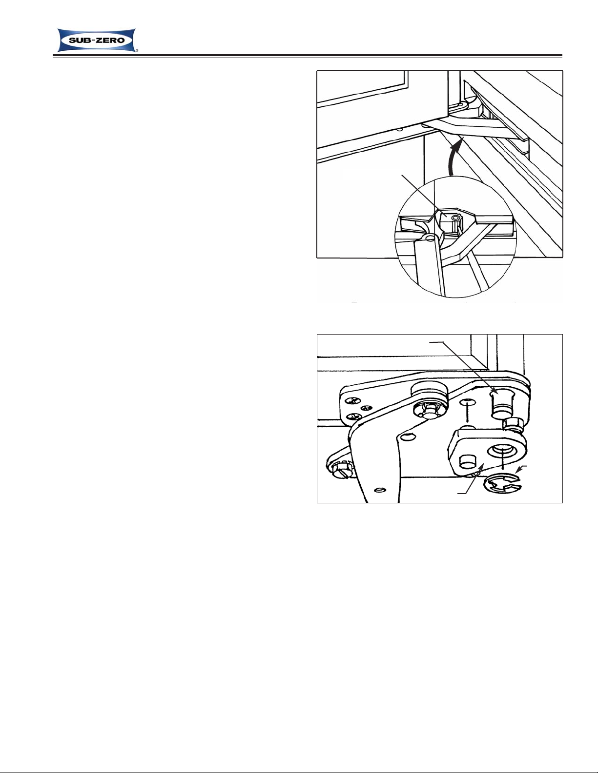
Figure 2-15. Door / Top Cabinet Hinge Adjustment
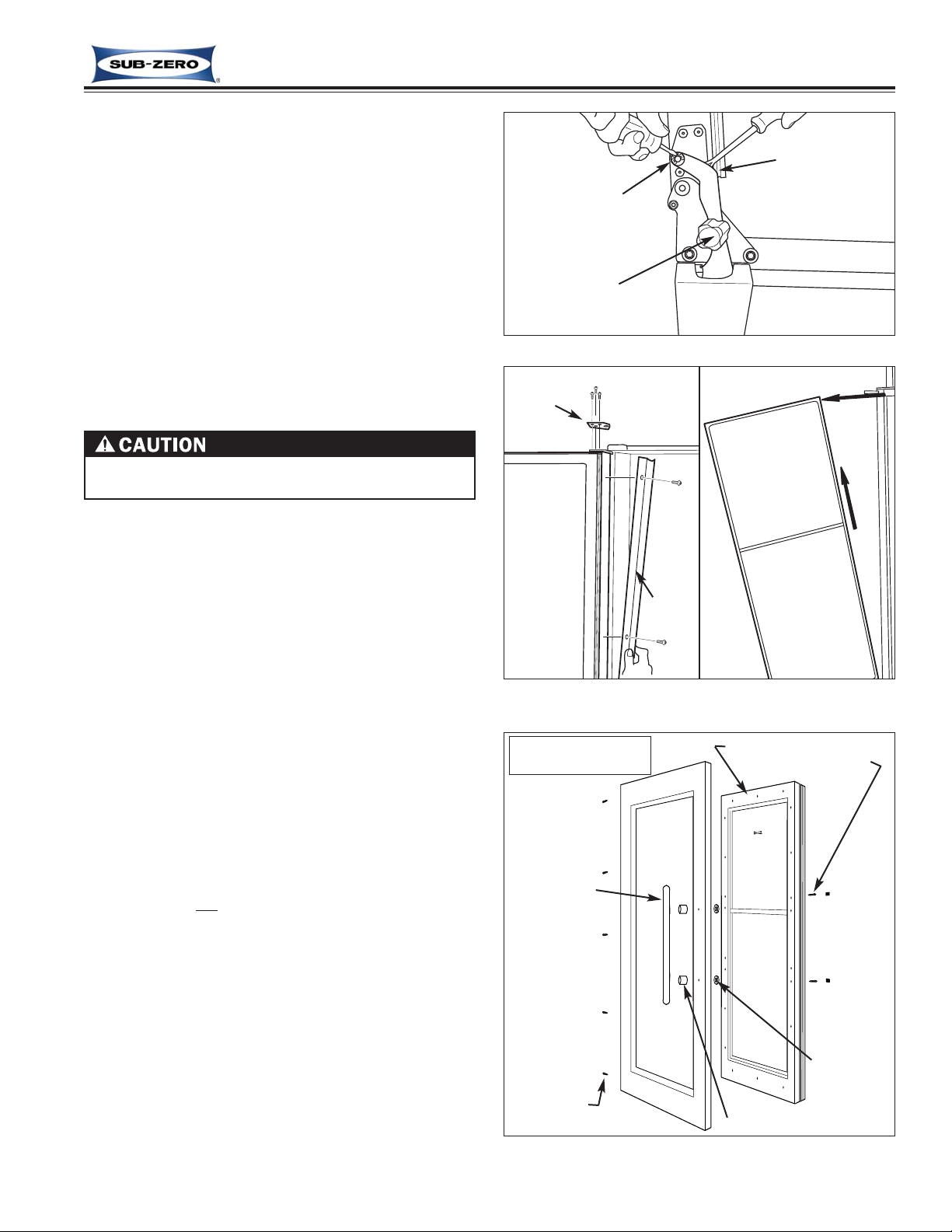
Figure 2-16. Door / Top Door Hinge Adjustment
Cabinet Hinge
Shipping Screws
Door Adjustment (424-2, 424FS-2)
NOTE: Unit must be level before adjusting door.
NOTE: If 424FS-2 door needs adjusting, stainless steel
wrap must be removed to adjust top cabinet hinge (See
Figure 2-14).
If unit is properly installed, blocked and leveled, it may
still be necessary to adjust door left to right and/or in
and out. Adjustments are performed at top and/or bot-
tom cabinet hinge(s) (See Figure 2-15).
1. Working on only one hinge at a time (top or bottom),
remove and discard two small Phillips head shipping
screws from cabinet hinge before attempting adjust-
ments.
2. Using a 1/8” Allen-wrench, loosen and “re-snug” cab-
inet hinge screws, allowing door adjustment.
3. Adjust door as required.
4. After adjusting door, tighten cabinet hinge screws
and check for proper door seal.
Door and/or Drawer Adjustment (427-2 & 427R-2)
NOTE: Door and/or drawers on models 427-2 & 427R-
2 are non-adjustable. Instead, door and/or drawer pan-
els must be adjusted if there is alignment problems.
Refer to Installation Manual.
NOTE: Unit must be level before adjusting door and/or
drawer panels.
Door Adjustment (430-2)
If unit is properly installed, blocked and leveled, it may
still be necessary to adjust door left to right and/or in
and out. Adjustments are performed at top and/or bot-
tom door hinge(s) (See Figure 2-16).
1. Working on only one hinge at a time (top or bottom),
remove and discard two small Phillips head shipping
screws from door hinge before attempting adjust-
ments.
2. Using a 1/8” Allen-wrench, loosen and “re-snug” door
hinge screws, allowing door adjustment.
3. Adjust door as required.
4. After adjusting door, tighten door hinge screws and
check for proper door seal.
Remove shipping
screws.
Loosen and re-snug
cabinet hinge
screws.
Top
Door Hinge
Door Hinge Screws
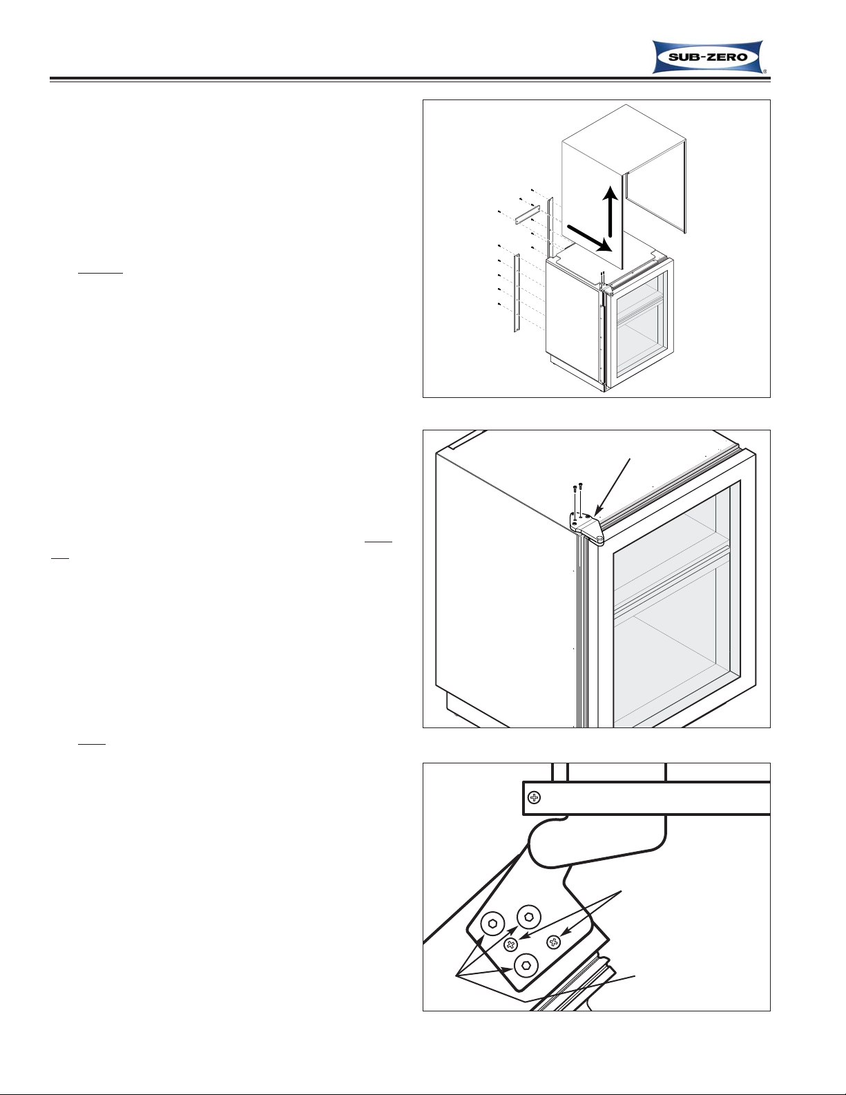
Figure 2-14. Wrap Removal
1. Remove
back brackets. 2. Slide
wrap
forward
& lift up
Wine Storage
Wine Storage (400-
(400-2
2)
)Series
Series Installation Information
2-7 #3758410 - Revision C - May, 2014
Door Stop Adjustment (427-2 & 427R-2)
Models 427-2 and 427R-2 have a 90° door stop cam
built into the hinge system. The 90° door stop cam is
located in the center portion of the hinge.
To adjust the stop, use a standard straight-blade screw-
driver to rotate cam until stop point is reached. (See
Figure 2-17)
NOTE: Door stop adjustment must be performed at
both bottom and top hinges.
Door Stop Installation (430-2)
For the model 430, optional 90° and 105° door stops
are available, free of charge from Parts Distributors
and/or Product Distributors. The part number for the
90° stop is #DS90, and the part number for the 105°
stop is #DS105.
To install a door stop, the door must be closed, then
(See Figure 2-18):
1. Slide door stop cam up onto bottom hinge pin.
2. Position stub on door stop into hole in cabinet
hinge.
3. Retain door stop by pushing E-Ring into groove at
end of bottom hinge pin, making sure E-ring is
clipped securely into groove.
Figure 2-17. Door Stop Adjustment
Figure 2-18. Door Stop Installation
E-Ring
Door Stop
Hinge Pin
90° Stop Cam
Installation Information Wine Storage
Wine Storage (400-
(400-2
2)
)Series
Series
2-8
#3758410 - Revision C - May, 2014
Figure 2-20. Poly Tape Removal
Figure 2-21. Stainless Steel Door Panel Removal
Poly Tape
Door Gasket
Door Frame
Handle
Screws
SS Handle
(Door Hinges &
Screws - not shown)
SS Panel
Poly
Tape
Door Assy
METAL DOOR PANELS MAY HAVE SHARP EDGES.
PROTECTIVE GLOVES SHOULD BE WORN WHEN
HANDLING PANELS.
DOOR PANELS MAY BE HEAVY OR UNSTABLE. IF
THEY WERE TO FALL, THEY COULD CAUSE SERI-
OUS PERSONAL INJURY.
Door Panel Removal and Installation (All Models)
Figure 2-19. Door Closer Removal
Door Closer
Hinge Pin
Classic, carBon and Platinum Stainless Steel Door
Panel Removal and Installation (424-2)
To remove a 424-2 SS door panel, the door must first
be removed from the unit.
To Remove the Door:
1. Remove mounting screws securing door closer to
the unit base (See Figure 2-19)
2. Slide door closer down off of bottom door hinge pin
NOTE: It may be necessary to lean unit back
slightly to create enough clearance between hinge
pin and floor.
3. Open door and extract screws from top door hinge.
4. Lean door away from unit slightly and lift door out of
bottom cabinet hinge.
To Remove a Stainless Steel Panel:
1. Lay door down and remove bottom door hinge and
switch depressor. (If lock and/or screws are pres-
ent on bottom handle side, remove them also.)
2. Remove Poly-tape under gasket on handle side
which covers handle mounting screw holes (See
Figure 2-20).
NOTE: Do not discard tape. It must be reapplied
when panel is reinstalled.
3. Extract handle mounting screws and pull handle
from front of door (See Figure 2-21).
4. Lift stainless steel panel from door.
NOTE: To install stainless steel panel, reverse steps
above.
Wine Storage
Wine Storage (400-
(400-2
2)
)Series
Series Installation Information
2-9 #3758410 - Revision C - May, 2014
Figure 2-23. Overlay Door Panel Removal
Door Assy
Poly
Tape
Panel
Mounting
Screws
Overlay Panel
SS Handle Shown (Handle may vary)
Figure 2-22. Poly Tape Removal
Poly Tape
Door Gasket
Door Frame
Overlay Door Panel Removal and Installation (424-2)
Overlay panels are attached to the door using screws
passing through the door frame from the rear, into the
panel. The handle may also be attached through the
door frame or just through the panel.
To Remove an Overlay Panel:
1. Open door.
2. Remove Poly-tape under gasket which covers
panel mounting screw holes (See Figure 2-22).
NOTE: Do not discard tape. It must be reapplied
when panel is reinstalled.
3. Extract panel mounting screws, and possibly handle
mounting screws. (See Figure 2-23)
4. Pull overlay panel from door.
NOTE: To install overlay panel, reverse steps above.
Installation Information Wine Storage
Wine Storage (400-
(400-2
2)
)Series
Series
2-10
#3758410 - Revision C - May, 2014
Figure 2-25. Door Panel Removal
Figure 2-26. Drawer Panel Removal
Drawer Panel
Mounting Bracket
- Upper
Drawer Panel
Mounting
Bracket
- Bottom
Door Panel Removal and Installation
(427-2 & 427R-2)
Models 427-2 and 427R-2 are NOT supplied with pan-
els from the factory. Panels are purchased separately.
Door panels are attached with screws passing from the
rear through the door frame into the panel. The handle
is attached to the panel.
To remove a door panel:
1. Open door.
2. Remove Poly-tape under gasket which covers
panel mounting screw holes (See Figure 2-24).
NOTE: Do not discard tape. It must be reapplied
when panel is reinstalled.
3. Extract panel mounting screws. (See Figure 2-25)
4. Pull panel from door.
NOTE: To install panel, reverse steps above.
Drawer Panel Removal and Installation (427R-2)
NOTE: Model 427R-2 is NOT supplied with panels
from the factory. Panels are purchased separately.
Drawer panels are attached using screws passing
through mounting brackets at the bottom of each draw-
er, and a dog-eared bracket on the back of the panel fit-
ting into slots in the face of the drawers. Handles are
attached to the panels.
To remove a drawer panel (See Figure 2-26):
1. Open drawer.
2. Extract the six screws at bottom drawer panel
bracket.
3. Pull bottom of drawer panel out slightly while pulling
downward.
NOTE: To install panel, reverse steps above.
Figure 2-24. Poly Tape Removal
Poly Tape
Door Gasket
Door Frame
Wine Storage
Wine Storage (400-
(400-2
2)
)Series
Series Installation Information
2-11 #3758410 - Revision C - May, 2014
Figure 2-29. Stainless Steel Door Panel Removal
Panel
Door Assy Handle
Screw
(Door Hinges &
Screws - not shown)
Handle
Door closer is spring loaded and may recoil quickly
when detached.
Hinge-Side
Panel Mounting Screw Handle Stand-off
Panel
Spacer/
Washer
Classic, carBon and Platinum Stainless Steel Door
Panel Removal and Installation (430-2)
To remove a 430-2 SS door panel, the door must first
be removed from the unit.
To Remove the Door:
1. Open door until hole in bottom cabinet hinge aligns
with hole in door closer arm (See Figure 2-27).
2. Insert short screwdriver up into the two holes.
NOTE: This screwdriver will be used to pry the
door closer arm back onto the door hinge stud.
3. Use a small straight-blade screwdriver to remove E-
ring which holds door closer arm to bottom door
hinge stud.
4. Pry door closer arm down off of door hinge stud.
Figure 2-27. Door Closer Disconnect
Remove
E-Ring
Pry down
Screwdriver
up into holes
Figure 7-28a.
Trim/Hinge Removal
Lean door
away from
unit and
lift up
Door
Trim
Door
Hinge
Figure 7-28b.
Door Removal
5. Remove hinge-side door trim (See Figure 7-28a).
6. With a 1/8” Allen-wrench and Phillips screwdriver,
extract all screws from top door hinge.
7. Lean door away from unit and lift off of bottom cabi-
net hinge (See Figure 7-28b).
NOTE: When reinstalling door, use screwdriver in
cabinet hinge hole and door closer arm hole to pry
door closer arm back onto the door hinge stud.
To Remove a Stainless Steel Panel:
1. Lay door down and remove bottom door hinge and
switch depressor at top of door. (If lock and/or
screws are present on top handle side, remove
them also.)
2. Remove panel mounting screws from hinge side of
door.
3. Remove Poly-tape under gasket on handle side
which covers handle mounting screw holes (See
Figure 2-29).
NOTE: Do not discard tape. It must be reapplied
when panel is reinstalled.
4. Extract handle mounting screws and pull handle
from front of door.
5. Lift stainless steel panel from hinge side first, pivot-
ing it off of handle side of door.
NOTE: To install stainless steel panel, reverse steps
above.
Installation Information Wine Storage
Wine Storage (400-
(400-2
2)
)Series
Series
2-12
#3758410 - Revision C - May, 2014
Figure 2-30. Trim Molding Removal
Figure 2-31. Framed and Overlay Handle / Handle
Side Trim & Door Panel Removal
Framed & Overlay Door Panel Removal / Installation
(430-2)
Framed and overlay panels are attached to the door by
sliding 1/4” (6 mm) thick edge of panel under door trim.
On the handle side, there may also be additional
screws passing through the door frame from rear into
the panel for increased support. Overlay handles may
also be attached through the door frame, or just through
the panel.
To remove a framed or overlay panel, the handle, or
trim on handle side must first be removed. Handles
and/or handle-side trim is secured to the door with
screws. The screw heads are then concealed by a
magnetic trim strip.
To Remove Handle or Handle-side Trim (See Figure
7-30 & 7-31):
1. Press a sticky piece of tape to center of magnetic
trim strip.
2. Pull tape so that trim strip bows away from door,
disengaging both ends of trim strip from the end-
caps.
3. With mounting screws exposed, extract the screws,
then pull handle (or handle-side trim) from door.
To Remove Panel (See Figure 7-31):
1. Slide panel towards handle side, and out from
under door trim.
NOTE: If the panel will not slide from under door
trim, panel mounting screws and/or handle mount-
ing screws may have been used.
a. Open door and remove Poly-tape from under
gasket.
b. Extract panel mounting screws, and/or handle
mounting screws.
c. Slide panel towards handle side, and out from
under door trim.
Magnetic
Trim Molding
Handle or
Handle-side
Trim
Screws
Piece of
Tape
Framed or
Overlay Panel

Other Sub-Zero Wine Cooler manuals

Sub-Zero ICB424 Owner's manual

Sub-Zero

Sub-Zero ICB424 Owner's manual

Sub-Zero Designer Series User manual

Sub-Zero

Sub-Zero Designer Series User manual

Sub-Zero WS-30 User manual

Sub-Zero

Sub-Zero WS-30 User manual

Sub-Zero DEU1550B/R User manual

Sub-Zero

Sub-Zero DEU1550B/R User manual

Sub-Zero 424FS Instructions for use

Sub-Zero

Sub-Zero 424FS Instructions for use

Sub-Zero ICB424 User manual

Sub-Zero

Sub-Zero ICB424 User manual

Sub-Zero 424 User manual

Sub-Zero

Sub-Zero 424 User manual

Sub-Zero 315W User manual

Sub-Zero

Sub-Zero 315W User manual

Sub-Zero 424 User manual

Sub-Zero

Sub-Zero 424 User manual

Sub-Zero 430 User manual

Sub-Zero

Sub-Zero 430 User manual

Sub-Zero IW-30CI User manual

Sub-Zero

Sub-Zero IW-30CI User manual

Sub-Zero 315W Instructions for use

Sub-Zero

Sub-Zero 315W Instructions for use

Sub-Zero UW24ORH User manual

Sub-Zero

Sub-Zero UW24ORH User manual

Sub-Zero 315W User manual

Sub-Zero

Sub-Zero 315W User manual

Sub-Zero ICBCL3050W/S User manual

Sub-Zero

Sub-Zero ICBCL3050W/S User manual

Sub-Zero IW-18 User manual

Sub-Zero

Sub-Zero IW-18 User manual

Sub-Zero ICB400 Series User manual

Sub-Zero

Sub-Zero ICB400 Series User manual

Sub-Zero 424 Owner's manual

Sub-Zero

Sub-Zero 424 Owner's manual

Sub-Zero WINE STORAGE Owner's manual

Sub-Zero

Sub-Zero WINE STORAGE Owner's manual

Sub-Zero 430 User manual

Sub-Zero

Sub-Zero 430 User manual

Sub-Zero WINE STORAGE User manual

Sub-Zero

Sub-Zero WINE STORAGE User manual

Sub-Zero ICB424 User manual

Sub-Zero

Sub-Zero ICB424 User manual

Sub-Zero 315W Guide

Sub-Zero

Sub-Zero 315W Guide

Sub-Zero 427G Guide

Sub-Zero

Sub-Zero 427G Guide

Popular Wine Cooler manuals by other brands

Indel Webasto Marine Isotherm Divino The One Installation and usage instructions

Indel Webasto Marine

Indel Webasto Marine Isotherm Divino The One Installation and usage instructions

Eurocave France Cave user manual

Eurocave

Eurocave France Cave user manual

Wolf Sub-Zero 424 user guide

Wolf

Wolf Sub-Zero 424 user guide

Baumatic BW18BL instruction manual

Baumatic

Baumatic BW18BL instruction manual

Igloo FRW1201 instruction manual

Igloo

Igloo FRW1201 instruction manual

U-Line Wine Captain user guide

U-Line

U-Line Wine Captain user guide

Koolatron KWT10BN user manual

Koolatron

Koolatron KWT10BN user manual

Haier HVTB18DABB user manual

Haier

Haier HVTB18DABB user manual

Ivation IVBWCC461DSS user guide

Ivation

Ivation IVBWCC461DSS user guide

Tefcold TFW 365-2 instruction manual

Tefcold

Tefcold TFW 365-2 instruction manual

Haier JC-125GMEF user manual

Haier

Haier JC-125GMEF user manual

Pkm WKS 52A instruction manual

Pkm

Pkm WKS 52A instruction manual

Vinotemp 2500SSR Installation instruction

Vinotemp

Vinotemp 2500SSR Installation instruction

commercial cool CCWT060TB user manual

commercial cool

commercial cool CCWT060TB user manual

Kalorik Chambrer WineBar with Dual Zone operating instructions

Kalorik

Kalorik Chambrer WineBar with Dual Zone operating instructions

CONTINENTAL EDISON JCF-124S Instructions for use

CONTINENTAL EDISON

CONTINENTAL EDISON JCF-124S Instructions for use

Silhouette Renoir SR001 owner's manual

Silhouette

Silhouette Renoir SR001 owner's manual

Summit SWC2149 owner's manual

Summit

Summit SWC2149 owner's manual

manuals.online logo
manuals.online logoBrands
  • About & Mission
  • Contact us
  • Privacy Policy
  • Terms and Conditions

Copyright 2025 Manuals.Online. All Rights Reserved.