manuals.online logo
Brands
  1. Home
  2. •
  3. Brands
  4. •
  5. Sunricher
  6. •
  7. Switch
  8. •
  9. Sunricher SR-ZG9100A-S User manual

Sunricher SR-ZG9100A-S User manual

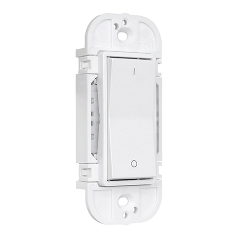
ZigBee In Wall Smart Switch 70110018
Function introduction
Important: Read All Instructions Prior to Installation
• DO NOT expose the device to moisture.
• DO NOT install with power applied to device.
Safety & Warnings
Operation
• ZigBee in wall smart switch based on latest ZigBee 3.0 protocol
• 100-240VAC Wide Input and Output Voltage
• Supports resistive loads, capacitive loads or inductive loads
• 1 channel output, max. load up to 4.8A
• Input and Output with Screw Terminals, Safe and Reliable
• Enables to control ON/OFF of connected light source
• ZigBee end device that supports Touchlink commissioning
• Can directly pair to a compatible ZigBee remote via Touchlink without coordinator
• Supports self-forming zigbee network without coordinator and add other devices to the network
• Supports find and bind mode to bind a ZigBee remote
• Supports zigbee green power feature and can bind max. 20 zigbee green power remotes
• Compatible with universal ZigBee gateway products
• Mini Size, Easy to be Installed into a standard size wall box
• Radio Frequency : 2.4GHz
• Waterproof grade: IP20
Input Voltage Output Voltage Output Current
Product Data
Size(LxWxH)
100-240VAC
Resistive load: max. 4.8A
Capacitive/Inductive load: max. 1.4A
100-240VAC 45.5x45x20.3mm
1.Do wiring according to connection diagram correctly.
Input Clusters
• 0x0000: Basic • 0x0003: Identify • 0x0004: Groups • 0x0005: Scenes • 0x0006: On/off
• 0x0b04: Electrical Measurement
Output Clusters
• 0x0019: OTA
ZigBee Clusters the device supports are as follows:
2.This ZigBee device is a wireless receiver that communicates with a variety of ZigBee compatible systems. This
receiver receives and is controlled by wireless radio signals from the compatible ZigBee system.
• 0x0702: Simple Metering • 0x0b05: Diagnostics
• Can operate under two-wire connection with no neutral lead or three-wire connection with neutral lead
• Soft start function,
• Works with various types of switches – momentary, toggle, three-way, etc.
• Active element: semiconductor electronic switch,
• To be installed in wall switch boxes of dimensions allowing for installation, conforming to provisions of
applicable regulations,
• The Bypass is an extension unit.
The switch operates under the following loads:
• Conventional incandescent and HV halogen light sources
• ELV halogen lamps (with electronic transformers)
• MLV halogen lamps (with ferromagnetic transformers)
• Compact fluorescent CFL tube lamps with electronic ballast
• Fluorescent tube lamps with electronic ballast
• Supported light sources (power factor > 0.5) with minimal power of 3W using the Bypass (depending on the
type of load)
Main Features:
“Reset” Key: factory
reset of the switch,
short press to turn
on/off load
AC power input
Load output
Switch input
(2-wire with No Neutral input)
(3-wire with Neutral input)
(2-wire with No Neutral output)
(3-wire with Neutral output)
Reset
LL NN
OUT AC 100-240V
S1
COM
In-wall Smart
Switch
Ratings:100-240V,50/60Hz,
MAX:1.4A ( )
MAX:4.8A ( )
3. Zigbee Network Pairing through Coordinator or Hub (Added to a Zigbee Network)
Step 1: Remove the device from previous zigbee network if it has already been added to, otherwise pairing will
fail. Please refer to the part "Factory Reset Manually".
Step 2: From your ZigBee Controller or hub interface, choose to add lighting device and enter Pairing mode as
instructed by the controller.
Step 3: Re-power on the device to set
it into network pairing mode
(connected light flashes twice
slowly), 15 seconds timeout, repeat
the operation.
Step 4: Connected light will blink 5
times and then stay solid on, then the
device will appear in your controller's
menu and can be controlled through
controller or hub interface.
Live
Neutral
Bypass
Reset
LL NN
OUT AC 100-240V
S1
COM
In-wall Smart
Switch
Ratings:100-240V,50/60Hz
MAX:1.4A ( )
MAX:4.8A ( )
LED indicator, stays off
when power on the switch, turns
on after added to a zigbee hub,
indicates (same status as connected
load) when program the switch
(network pairing, touchlink,
factory reset)
Live
Neutral
Bypass
Reset
LL NN
OUT AC 100-240V
S1
COM
In-wall Smart
Switch
Ratings:100-240V,50/60Hz
MAX:1.4A ( )
MAX:4.8A ( )
4. TouchLink to a Zigbee Remote
5. Removed from a Zigbee Network through Coordinator or Hub Interface
From your ZigBee controller or hub
interface, choose to delete or reset the
lighting device as instructed. The
connected light blinks 3 times to indicate
successful reset.
Step 1: Method 1: Short press
“Reset” button (or re-power on
the device) 4 times to start
Touchlink commissioning
immediately, 180S timeout,
repeat the operation.
Method 2: Re-power on the
device, Touchlink
commissioning will start after
15S if it’s not added to a
zigbee network, 165S timeout.
Or start immediately if it’s
already added to a network,
180S timeout. Once timeout,
repeat the operation.
Step 4: There shall be indication
on the remote for successful link
and connected light will flash
twice.
Zigbee
Remote < 10cm
Step 2: Bring the remote or touch
panel within 10cm of the lighting
device.
Step 3: Set the remote or touch
panel into Touchlink
commissioning,
please refer to corresponding
remote or touch panel manual to
learn how.
Note: 1) Directly TouchLink (both not added to a ZigBee network), each device can link with 1 remote.
2) TouchLink after both added to a ZigBee network, each device can link with max. 30 remotes.
3) To control by both gateway and remote, add remote and device to network first then TouchLink.
4) After TouchLink, the device can be controlled by the linked remotes.
6. Factory Reset Manually
Step 2: Connected light
will blink 3 times to
indicate successful reset.
Step 1: Short press “Reset.”
key for 5 times continuously
or re-power on the device for
5 times continuously if
the “Prog.” key is not
accessible.
Note: 1) If the device is already at factory
default setting, there is no indication
when factory reset again .
2) All configuration parameters will
be reset after the device is reset or
removed from the network.
7. Factory Reset through a Zigbee Remote (Touch Reset)
Note: Make sure the device already added to a network, the remote added to the same one or not added to any
network.
Step 1: Re-power on the
device to start TouchLink
Commissioning, 180
seconds timeout, repeat
the operation.
Step 4: There shall be indication
on the remote and connected light
flashes 3 times for successful
reset.
Zigbee
Remote < 10cm
Step 2: Bring the remote or touch
panel within 10cm of the lighting
device.
Step 3: SSet the remote or touch
panel into Touch Reset procedure
to reset the device, please refer to
corresponding remote or touch
panel manual to learn how.
8. Find and Bind Mode
Step 1: Short press “Reset.”
button 3 times (Or re-power
on the device (initiator node)
3 times) to start Find and
Bind mode (connected light
flashes slowly) to find and
bind target node, 180
seconds timeout, repeat the
operation.
Zigbee
Remote
Step 2: Set the remote or touch
panel (target node) into find
and bind mode, and enable it
to find and bind initiator, please
refer to corresponding remote
or touch panel manual.
Step 3: There shall be
indication on the remote or
touch panel that it bind the
device successfully and can
control it then.
Note: Make sure the device and remote already added to the same zigbee network.
9. Learning to a Zigbee Green Power Remote
Step 1: Short press “Reset.”
button 4 times (Or re-power
on the device 4 times) to
start Learning mode
(connected light flashes
twice), 180 seconds timeout,
repeat the operation.
Step 2: Set the green power
remote into Learning mode,
please refer to its manual.
Step 3: Connected light will
flash twice to indicate
successful learning. Then the
remote can control the device.
Note: Each device can learn to max. 20 zigbee green power remotes.
Zigbee
Green Power
Remote
Live
Neutral
Bypass
Reset
LL NN
OUT AC 100-240V
S1
COM
In-wall Smart
Switch
Ratings:100-240V,50/60Hz
MAX:1.4A ( )
MAX:4.8A ( )
Live
Neutral
Bypass
Reset
LL NN
OUT AC 100-240V
S1
COM
In-wall Smart
Switch
Ratings:100-240V,50/60Hz
MAX:1.4A ( )
MAX:4.8A ( )
Live
Neutral
Bypass
Reset
LL NN
OUT AC 100-240V
S1
COM
In-wall Smart
Switch
Ratings:100-240V,50/60Hz
MAX:1.4A ( )
MAX:4.8A ( )
Live
Neutral
Bypass
Reset
LL NN
OUT AC 100-240 V
S1
COM
In-wall Smart
Switch
Ratings:100-240V,50/60Hz
MAX:1.4A ( )
MAX:4.8A ( )
Reset
LL NN
OUT AC 100-240V
S1
COM
In-wall Smart
Switch
MAX:1.4A ( )
MAX:4.8A ( )
Ratings:100-240V,50/60Hz
Live
Neutral
Bypass
Reset
LL NN
OUT AC 100-240V
S1
COM
In-wall Smart
Switch
Ratings:100-240V,50/60Hz
MAX:1.4A ( )
MAX:4.8A ( )
11. Setup a Zigbee Network & Add Other Devices to the Network (No Coordinator Required)
Step 1: Short press “Reset.”
button 4 times (Or re-power
on the device 4 times) to
enable the device to setup a
zigbee network (connected
light flashes twice) to
discover and add other
devices, 180 seconds
timeout, repeat the operation.
Zigbee
Remote
< 10cm
TouchLink
10. Delete Learning to a Zigbee Green Power Remote
Step 1: Short press “Reset.”
button 3 times (Or re-power
on the device 3 times) to start
delete Learning mode
(connected light flashes
slowly), 180 seconds timeout,
repeat the operation.
Zigbee
Green Power
Remote
Step 2: Set the paired green
power remote into Learning
mode, please refer to its manual.
Step 3: Connected light will
flash 4 times to indicate
successful deleting.
Wiring Diagram
Out - output terminal of the switch (controlling connected light source)
S1 - terminal for switch (has the option of entering the device in inclusion/exclusion mode)
COM - terminal for grounding to the switch connected to the switch
Notes for the diagrams:
L - terminal for live lead
N - terminal for neutral lead
Compatible load types and recommended values of power for supported loads:
Supported load types 100-240V~
20-1000W @ 230V
20-500W @ 110V
Resistive loads
Conventional incandescent and
halogen light sources
Capacitive loads
Fluorescent tube lamp
(compact / with electronic ballast),
electronic transformer, LED
Inductive loads
Ferromagnetic transformers
Reset
LL NN
OUT AC 100-240V
S1
COM
In-wall Smart
Switch
Ratings:100-240V,50/60Hz
MAX:1.4A ( )
MAX:4.8A ( )
No Bypass Used:
20-300W @ 230V
20-150W @ 110V
20-300W @ 230V
20-150W @ 110V
Using Bypass:
3-300W @ 230V
3-150W @ 110V
100-240V~
Live
Neutral
Bypass
Reset
LL NN
OUT AC 100-240V
S1
COM
In-wall Smart
Switch
Ratings:100-240V,50/60Hz
MAX:1.4A ( )
MAX:4.8A ( )
Supported external switch types (should be configured by factory setting):
1) Push switch (default factory setting)
2) Normal On/Off switch (should be configured by factory setting upon request)
(2) 3-Wire Connection With Neutral Lead
PUSH
Live
Neutral
The Bypass is a device designed to work with the micro smart dimmer. It should be used in case of connecting
LED bulbs or energy saving compact fluorescent lamps. The Bypass prevents flickering of the LED lights and
glowing of the turned off compact fluorescent lamps. In the case of 2-wire connection, the Bypass allows to
reduce minimum power of load required by the dimmer for correct operation. The Bypass provides powering of
the dimmer in case of controlling the low loads of minimum power down to 3W (for cosφ>0.5).
Live
Neutral
Bypass
(1) 2-Wire Connection With No Neutral Lead
PUSH
NOTE: Switch connected to the S1 terminal activates the basic functionality of the dimmer (turning the light
on/off).
Live
Neutral
PUSH
With PUSH LV With PUSH
Live
Neutral
Bypass
PUSH
With PUSH LV With PUSH
Reset
LL NN
OUT AC 100-240V
S1
COM
In-wall Smart
Switch
MAX:1.4A ( )
MAX:4.8A ( )
Ratings:100-240V,50/60Hz
Reset
LL NN
OUT AC 100-240V
S1
COM
In-wall Smart
Switch
MAX:1.4A ( )
MAX:4.8A ( )
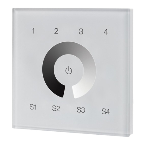
Ratings:100-240V,50/60Hz
Reset
LL NN
OUT AC 100-240V
S1
COM
In-wall Smart
Switch
MAX:1.4A ( )
MAX:4.8A ( )
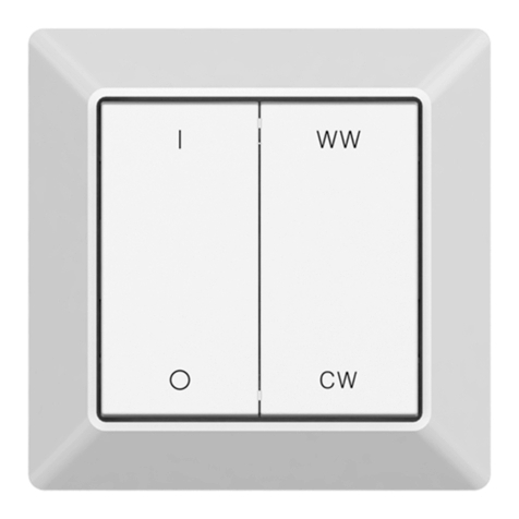
Ratings:100-240V,50/60Hz
NOTE: Switch connected to the S1 terminal activates the basic functionality of the dimmer (turning the light
on/off).
(3) Multiple Momentary or Push Switches Connection
With PUSH LV
With PUSH
Live
Neutral
Reset
LL NN
OUT AC 100-240V
S1
COM
In-wall Smart
Switch
MAX:1.4A ( )
MAX:4.8A ( )
Ratings:100-240V,50/60Hz
Reset
LL NN
OUT AC 100-240 V
S1
COM
In-wall Smart
Switch
MAX:1.4A ( )
MAX:4.8A ( )
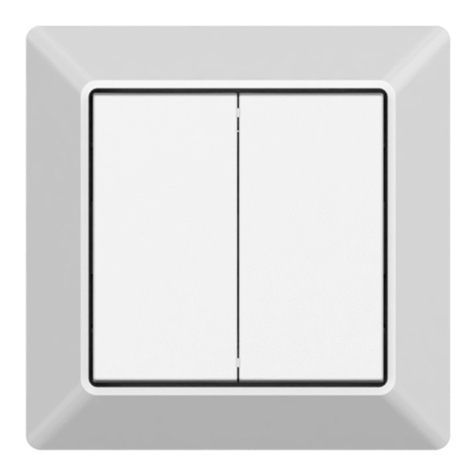
Ratings:100-240V,50/60Hz

Other Sunricher Switch manuals

Sunricher SR-SBP2801K4-FOS User manual

Sunricher

Sunricher SR-SBP2801K4-FOS User manual

Sunricher SR-ZGP2801K4-DIM User manual

Sunricher

Sunricher SR-ZGP2801K4-DIM User manual

Sunricher Azoula AZ220614A User manual

Sunricher

Sunricher Azoula AZ220614A User manual

Sunricher SR-ZG9100A User manual

Sunricher

Sunricher SR-ZG9100A User manual

Sunricher SR-ZGP2801K4-DIM-G2-E User manual

Sunricher

Sunricher SR-ZGP2801K4-DIM-G2-E User manual

Sunricher SR-ZGP2801K4-DIM User manual

Sunricher

Sunricher SR-ZGP2801K4-DIM User manual

Sunricher SR-GW-ZG User manual

Sunricher

Sunricher SR-GW-ZG User manual

Sunricher SR-ZGP2801K4-5C User manual

Sunricher

Sunricher SR-ZGP2801K4-5C User manual

Sunricher R-SBP2801K4-FOS-E User manual

Sunricher

Sunricher R-SBP2801K4-FOS-E User manual

Sunricher SR-ZGP2801K2-DIM User manual

Sunricher

Sunricher SR-ZGP2801K2-DIM User manual

Sunricher SR-ZGP2801K2-DIM-E User manual

Sunricher

Sunricher SR-ZGP2801K2-DIM-E User manual

Sunricher SR-ZG9080A User manual

Sunricher

Sunricher SR-ZG9080A User manual

Sunricher SR-ZGP2801K4-DIM-S2-E User manual

Sunricher

Sunricher SR-ZGP2801K4-DIM-S2-E User manual

Sunricher SR-ZGP2801K4-DIM-E User manual

Sunricher

Sunricher SR-ZGP2801K4-DIM-E User manual

Sunricher SR-ZG9101SAC-HP-SWITCH User manual

Sunricher

Sunricher SR-ZG9101SAC-HP-SWITCH User manual

Sunricher SR-ZGP2801K4-DIM-S2 User manual

Sunricher

Sunricher SR-ZGP2801K4-DIM-S2 User manual

Sunricher SR-ZGP2801K2-DIM User manual

Sunricher

Sunricher SR-ZGP2801K2-DIM User manual

Sunricher ZG9001T4-DIM-EU User manual

Sunricher

Sunricher ZG9001T4-DIM-EU User manual

Sunricher SR-ZG2833PAC-S4 User manual

Sunricher

Sunricher SR-ZG2833PAC-S4 User manual

Sunricher SR-2830A-AC User manual

Sunricher

Sunricher SR-2830A-AC User manual

Sunricher SR-ZGP2801K4-CCT-E User manual

Sunricher

Sunricher SR-ZGP2801K4-CCT-E User manual

Sunricher SR-ZGP2801K4-CCT-E-US User manual

Sunricher

Sunricher SR-ZGP2801K4-CCT-E-US User manual

Sunricher SR-ZV9100A-A User manual

Sunricher

Sunricher SR-ZV9100A-A User manual

Popular Switch manuals by other brands

Vetus BPSPE installation instructions

Vetus

Vetus BPSPE installation instructions

Crystal Image Technologies Cat5-IP08 manual

Crystal Image Technologies

Crystal Image Technologies Cat5-IP08 manual

Salus miniSmartPlug user guide

Salus

Salus miniSmartPlug user guide

Siemens SIRIUS 3TY7561-1UA00 operating instructions

Siemens

Siemens SIRIUS 3TY7561-1UA00 operating instructions

SICK PBS Series operating instructions

SICK

SICK PBS Series operating instructions

3Com PathBuilder S21x installation manual

3Com

3Com PathBuilder S21x installation manual

Philips UID8600 quick start guide

Philips

Philips UID8600 quick start guide

Lindy 32520 user manual

Lindy

Lindy 32520 user manual

TP-Link TL-SG108PE installation guide

TP-Link

TP-Link TL-SG108PE installation guide

H3C S7500 Series Operation manual

H3C

H3C S7500 Series Operation manual

Edge-Core AS6700-32X installation guide

Edge-Core

Edge-Core AS6700-32X installation guide

NTI UNIMUX Series Installation and operation manual

NTI

NTI UNIMUX Series Installation and operation manual

Jlso Tec Trade VH M 1 1 1 Series operating manual

Jlso Tec Trade

Jlso Tec Trade VH M 1 1 1 Series operating manual

Bdcom S1518-16P-330 user guide

Bdcom

Bdcom S1518-16P-330 user guide

B+B SmartWorx ESWGP206-2SFP-T user manual

B+B SmartWorx

B+B SmartWorx ESWGP206-2SFP-T user manual

Belden Hirschmann MACH102 Series user manual

Belden

Belden Hirschmann MACH102 Series user manual

Planex SWP-0224FP user manual

Planex

Planex SWP-0224FP user manual

Altronix HubWayDS Series installation guide

Altronix

Altronix HubWayDS Series installation guide

manuals.online logo
manuals.online logoBrands
  • About & Mission
  • Contact us
  • Privacy Policy
  • Terms and Conditions

Copyright 2025 Manuals.Online. All Rights Reserved.