manuals.online logo
Brands
  1. Home
  2. •
  3. Brands
  4. •
  5. SunSetter
  6. •
  7. Accessories
  8. •
  9. SunSetter Platinum Plus Guide

SunSetter Platinum Plus Guide

For Technical Support visit us at hp://ownerscorner.sunseer.com,
e-mail contactus@sunseer.com, or Call Toll Free 800-670-7071 • Fax 877-224-4944
©SunSeer Products, 184 Charles Street, Malden, MA 02148
Planum Plus Semi-Cassee Awning
Fabric Replacement Instrucons
* Helpers Needed *
Tools Needed: Step Ladders, #2 Phillips Screwdriver and 6mm Allen wrench.
Parts Supplied: Fabric and Valance.
WARNING: FAILURE TO FOLLOW THESE INSTRUCTIONS CAN RESULT IN PERSONAL INJURY!! PLEASE
READ THESE INSTRUCTIONS IN ITS ENTIRETY BEFORE ATTEMPTING TO COMPLETE THIS PROCESS.
PLEASE NOTE THAT LEFT AND RIGHT REFERENCES ARE AS YOU ARE FACING THE HOUSE.
1. Open the Awning to the fully extended posion.
2. Unplug the power cord from the wall outlet.
3. Using the Manual Crank Wand, connue to unroll the
Fabric unl you expose the Fabric Slot in the Roller Bar
and create maximum slack in the Fabric.
a. The Lateral Arms will be fully extended and the Fabric
will lay loosely over the fully extended Arms.
b. The Fabric Slot in the Roller Bar will be facing forward,
toward the opening in the Housing. See Fig 2.
Before beginning, please familiarize yourself with the Awning and components in Figure 1.
Figure 2
Fabric shown with
maximum slack.
Fabric Slot in Roller
Bar exposed and,
facing forward.
Manual
Override
Manual
Crank Wand
Motor inside assembly
Lateral Arm
Fabric on Roller Bar
Figure 1
Awning must be
open all the way
unl Fabric sags
Roller Bracket
End Plate Assembly
Plasc Roller
Bracket Caps
2
4. Remove the Plasc Roller Bracket Caps from the
opposite end of the Motor side of the Semi-
Cassee Awning. See Figure 1.
Note: Fabric slides out of the non-motorized end
of the Roller Bar. Leave the Motor end intact.
5. Remove the four (4) Phillips screws from the
Roller Bracket End Plate assembly on the
NON-MOTORIZED end of the Awning, but
NOT the Allen Cap Bolts. Requires a #2 Phillips
screwdriver. See Figure 3.
6. Loosen the Allen Cap
Bolt on the Roller
Bracket, where it
connects to the Square
Bar. Requires a 6mm
Allen wrench. See
Figure 4.
7. Remove the enre
Roller Bracket End Cap
assembly from Awning.
8. ON THE OPPOSITE
SIDE OF THE MOTOR,
remove the two (three
screws for the PRO
Front Bar) Phillips
screws from the End
Plate of the Front Bar.
See Figure 5.
9. For PRO Front Bar ONLY, remove the Allen Set
Screw from the Valance Slot if the Valance is to be
replaced.
NOTE THE ORIENTATION OF THE FABRIC:
The hemmed (folded) edges on each side of the
Fabric are always facing down.
Roller Bracket Bolt
Square
Bar
Roller
Bracket
Figure 4
Figure 5
Front Bar
End
Plate
Awning
Fabric
Valance
For PRO Model with Motor on LEFT side, go to Step 21, next page.
10. With your helper, pull the old Fabric out of the
Roller Bar and Front Bar slots AT THE SAME TIME.
If replacing the Valance as well, remove the old
Valance from its slot in the Front Bar.
11. Remove the new Fabric from its packaging. Orient
it with the hems facing down.
Note: The Fabric must be inserted into the Roller
Bar and Front Bar Slots at the same me. You
might have to do so in small steps, alternang
from one bar to the other.
CAUTION: To prevent damage to the Fabric, have
your helper direct the Fabric into the slots, while
you slowly pull the Fabric through the slots to
the other end.
12. With your helper, carefully insert the Fabric into
the slots on the Roller Bar and Front Bar. You
might have to hold the Front Bar steady while
doing so. Repeat for the Valance.
13. Aach the Roller Bracket End Cap assembly to the
Awning. Tighten the #2 Phillips screws, then the
6mm Roller Bracket Bolt.
14. Center the Valance in the Front Bar.
15. Center the Fabric to align with the Valance.
16. Trim the gray cords to t.
17. Reinstall the End Plate on the Front Bar with the
two (see Figure 5) Phillips screws (three screws
for the PRO model. Trim the gray cords to t.
Note: For PRO Front Bars, install the Allen Set
Screw in the Valance Slot.
18. While keeping the Fabric reasonably stretched
on the Roller Bar, use the Manual Crank Wand
to slowly roll the Fabric onto the Roller Bar, unl
both arms start to close.
Note: The Fabric should roll OVER THE TOP and
onto the Roller Bar.
CAUTION: It is important the Fabric be rolled up
ghtly on the Roller Bar before operang the
Motor. Failure to do so can cause the electronic
Motor to lose stop posion sengs, which will
require reseng the Motor stop posions.
19. Plug the power cord back into the outlet.
20. Test the Awning for proper operaon.
Note: If you need to reset the Motor stop
posion sengs, refer to the enclosed
instrucons on how to reset the Motor stops.
Remove four (4)
#2 Phillips screws
Figure 3
Roller Bracket
End Plate Assy
3
24. Insert the Manual Crank Wand into the Crank
Loop on the front bar. See Figure 7.
21. Remove the Plasc Roller Bracket Cap from the
right side of the Awning (opposite end of the
Motor). See Figure 1.
Note: Fabric slides out of the non-motorized end
of the Roller Bar. Leave the Motor end intact.
22. Remove the four (4) Phillips screws from the
Roller Bracket End Cap on the NON-MOTORIZED
end of the Awning, but NOT the Allen Cap Bolts.
Requires a #2 Phillips screwdriver. See Figure 5.
26. ON THE OPPOSITE SIDE OF THE MOTOR, remove
the three Phillips screws from the End Plate of the
Front Bar and remove the End Plate. See Figure 8.
Note: Use care so that loose components of the
Crank Assembly are not misplaced. See Figure 8.
For PRO Model with Motor on LEFT side, proceed below:
Remove four (4)
#2 Phillips screws
Figure 5
23. Loosen the Allen
Cap Bolt on the
Roller Bracket,
where it connects
to the Square Bar.
Requires a 6mm
Allen wrench. See
Figure 6.
Roller Bracket Bolt
Square
Bar
Roller
Bracket
Figure 6
27. NOTE THE ORIENTATION OF THE FABRIC:
Hemmed (folded) edges on each side of the Fabric
are always facing down.
28. With your helper, pull the old Fabric out of the
Roller Bar and Front Bar slots AT THE SAME TIME.
If replacing the Valance as well, remove the old
Valance from its slot in the Front Bar.
29. Remove the new Fabric from its packaging. Orient
it the same way as explained in Step 25.
Note: The Fabric must be inserted into the Roller
Bar and Front Bar Slots at the same me. You
might have to do so in small steps, alternang
from one Bar to the other.
CAUTION: To Prevent Damage to the Fabric, Have
Your Helper direct the Fabric into the Slots, while
You Slowly Pull the Fabric through the Slots, to
the Other End.
30. With your helper, carefully insert the Fabric into
the slots on the Roller Bar and Front Bar. You
might have to hold the Front Bar steady while
doing so. Repeat for the Valance.
31. Center the Valance in the Front Bar.
32. Center the Fabric to align with the Valance.
33. Trim the gray cords to t.
Figure 7
Figure 8
Remove Right
End Plate with
Gear, Washer,
and Drive Sha.
25. Turn the Crank counter-clockwise to unroll the
Weather Breaker Panel unl the Panel is fully
extended.
4
34. Aach the Roller Bracket End Plate assembly to
the Awning. Tighten the #2 Phillips screws, then
the 6mm Roller Bracket Bolt.
35. Reinstall the End Plate on the Front Bar with the
three Phillips screws (see Figure 9), and roll the
Weather Breaker Front Panel completely up.
36. Using the manual Crank Wand, roll up the Front
Weatherbreaker Panel.
37. While keeping the Fabric reasonably stretched
on the Roller Bar, use the Manual Crank Wand
to slowly roll the Fabric onto the Roller Bar, unl
both Lateral Arms start to close and the Fabric
ghtens.
38. Plug the power cord back into the outlet.
Note: It is important the Fabric be manually
rolled up ghtly on the Roller Bar before
operang the Motor. Failure to do so can cause
the Motor to lose stop posion sengs, which
will require reseng the Motor stop posions.
39. Test the Awning and Weather Breaker Panel for
proper operaon.
Note: If you need to reset the Motor stop
posion sengs, refer to the enclosed
instrucons (Appendix A) on how to reset the
Motor stops.
Figure 9
5
APPENDIX A
Reseng Remote Communicaon and Reprogramming the Motor
This procedure will completely reset the communicaon between the Remote Transmier and Motor, as well
as erase and reprogram the Open and Closed stop posion sengs of the Motor.
This procedure programs the Awning Motor to accept commands from one primary Remote Transmier.
This procedure overwrites the factory set Open and Closed posions with new Open and Closed posions.
Note: To ONLY change the Open and Close preset posions, follow the procedure in Appendix A on Page 22.
Tools needed: A pen or similar poinng device is needed to press and hold the Programming Buon.
To ADD an addional Control Device (such as another Remote or Channel, or a Wirless Wall Switch);
• Press the Programming buon on the back of the Transmier that was supplied with the Awning unl
the motor “jogs.”
• On the addional Control Device, press the Programming buon unl the motor “jogs,” then release.
To DELETE a Control Device, repeat the two steps listed above and the addional Control Device is removed.
To Add or Delete a Control Device (Transmier)
WARNING: ALL STEPS MUST BE FOLLOWED EXACTLY AND COMPLETELY.
1. Set the Remote Transmier to Channel 1 (for single channel Remote, skip this step).
2. Press and Hold the my buon; the red LED light should blink for at least 5 seconds.
3. Disconnect Power for two (2) full seconds.
4. Connect Power for ten (10) full seconds.
5. Disconnect Power for two (2) full seconds.
6. Connect Power. The Awning should move, then stop on its own.
7. Press and hold the Programming buon for ten (10) seconds, watching for two (2)
separate jogs back and forth, several seconds apart.
Note: A single jog is dened as a quick two-direcon movement of the motor.
8. Press and Hold the CLOSE and OPEN buons together, release when the Awning jogs.
Note: The Awning now moves ONLY while holding down the CLOSE or OPEN buon.
9. Press the OPEN buon to check the direcon of the motor.
Note: The fabric must roll from the top of the Roller Bar, when opening the Awning.
10. If the direcon is incorrect, change direcon by holding the my buon unl the motor jogs.
Press the OPEN buon again to check for the correct direcon of the motor rotaon.
11. Move the Awning to the desired Closed posion. Note: Fabric must roll over top of Roller Bar.
12. Press and Hold the my and OPEN buons together; release when the Awning begins to Open.
13. Press the my buon to Stop the Awning at the desired Open seng.
14. Make desired adjustments to the Open posion. The Fabric will be ght and Arms slightly bent.
15. Press and Hold the my and CLOSE buons simultaneously; release them when the Awning
begins to Close. Let the Awning stop on its own at the Closed posion set in step 11.
16. Press and Hold the my buon; release when the Awning jogs. This step stores the new Open
and Close posions.
SET PROPER DIRECTION OF MOTOR ROTATION
SET THE CLOSED AND OPEN POSITIONS
PREPARE MOTOR - Read these instrucons FIRST, completely and thoroughly
17. Press and Hold the Programming buon; wait for a jog. This completes the procedure.
Note: The Awning now operates with a touch and release of the OPEN or CLOSE buon.
18. Test the Awning for correct one-touch operaon, using the OPEN and CLOSE buons.
FINALIZE PROGRAMMING OF MOTOR
Note: If steps 8 - 15 fail, unplug the Awning, plug it back in, then begin again from step 8.
OPEN
Front View
my
CLOSE
Indicator Lights
Rear View
Programming
Buon is
located
inside
this small
opening
Channel
Selector
Buon.
SunSeer Products, 184 Charles Street, Malden, MA 02148
November 14, 2019 INS186-Semi-Cassette_Fabric_Repl
Add a Wireless Wind Sensor
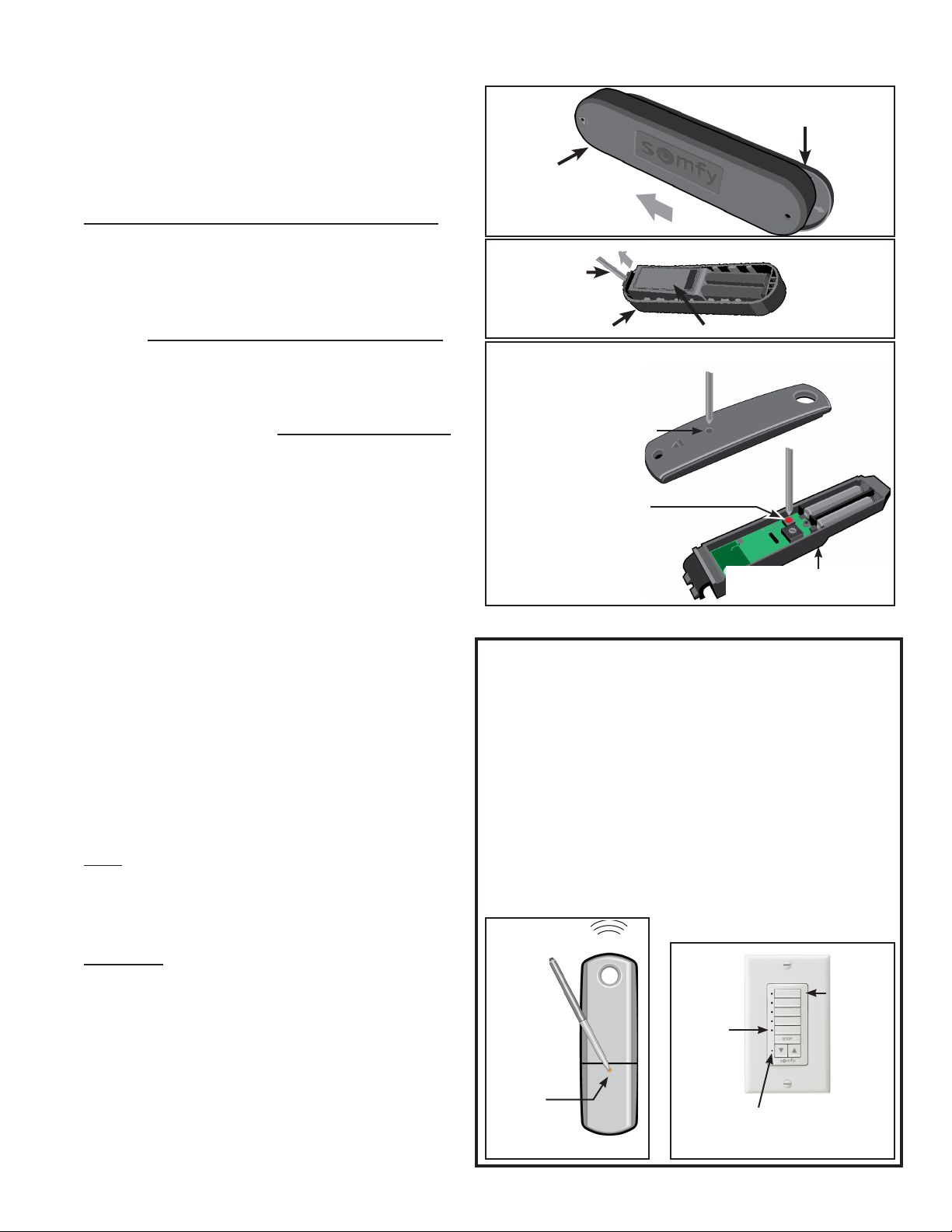
1. Remove the Wireless Wind Sensor Housing from
the Mounng Plate on the Awning. See Figure 1.
2. Remove the Sensor Body from the Sensor Housing
using a small at blade screwdriver. See Figure 2.
3. Press the Programming Buon on the back of the
Remote Transmier that operates the Awning
(See Figure 3) unl the Motor “jogs”. A “jog” is a
short back and forth movement of the motor.
4. Press the Programming Buon located inside the
Sensor (See Figure 3) unl the Motor “jogs,” then
release. The LED on the Sensor Body will blink.
If the LED does not blink, replace the two AAA
baeries, unplug the motor then plug it back in,
then restart this procedure at Step 3..
5. Replace the Wind Sensor on the Mounng Plate.
6. Test the Wireless Wind Sensor - Shake the
Awning Front Bar up and down (li the Front
Bar approximately one foot, then drop it) quickly
4 or more mes in a row (for approximately 12
seconds) to simulate the eect of strong wind; this
should cause the Awning to automacally close.
7. If the Awning does not close automacally:
• repeat Step 6 several more mes by strongly
shaking the Front Bar up and down quickly. To
shake the Front Bar, li the Bar unl strong
resistance is met, then allow the Bar to drop
freely. Repeat quickly.
• If the Awning sll does not close automacally,
repeat Steps 1 - 6 several more mes with a
NEW SET OF BATTERIES.
• If the problem connues, please call SunSeer
Customer Service at 800-670-7071.
Note: The Awning Motor will not accept a
command from the Remote Transmier for up
to 1 minute aer the Wireless Wind Sensor has
retracted the Awning three mes.
WARNING: YOU MUST BE CERTAIN THAT
THE WIRELESS WIND SENSOR IS INSTALLED,
PROGRAMMED AND OPERATING PROPERLY.
FAILURE TO DO SO MAY RESULT IN THE WIRELESS
WIND SENSOR NOT BEING ABLE TO CLOSE YOUR
AWNING DURING WINDY CONDITIONS, WHICH
COULD CAUSE DAMAGE AND PERSONAL INJURY.
IF THE MOTOR DIRECTION IS REVERSED THE
SENSOR WILL EXTEND (OPEN) THE AWNING IN
WINDY CONDITIONS, INSTEAD OF CLOSING IT.
Add a Wireless Wall Switch
1. Press the Programming Buon (recessed inside the opening)
on the rear of the Remote Transmier (see Figure 1), that
controls your Awning unl it responds with a movement.
2. Briey press the Channel Select Buon for the channel
of the Mul-Channel Wall Switch that you want to use to
control your Awning (see Figure 2). The adjacent LED will
light up for 10 seconds. Using a paper clip or similar device,
press the Programming Buon located on the Wall Switch
unl the Motor responds with a movement.
3. Your Wall Switch is set to operate your SunSeer Awning.
Test the Awning now for proper operaon.
Figure 1
Rear
Programming
Buon is
recessed
inside this
small opening
Remote Transmitter
Figure 2
Acve
Channel
Indicator
Lights
Channel
Selector
Buons
Programming
Buon is
recessed inside
this small
opening
Multi-Channel Wall Switch
Figure 2
Sensor Housing
Screwdriver
Sensor Body
Figure 3
Remote Transmier
THEN, press the
Programming Buon
inside the Wireless
Wind Sensor.
FIRST, press the
Programming Buon
inside small opening
on back of Remote.
Sensor Body removed
from the Housing
Figure 1 Mounng
Plate
Sensor
Housing
Slide Housing to the LEFT to
remove from Mounng Plate

Other SunSetter Accessories manuals

SunSetter EASYSHADE Guide

SunSetter

SunSetter EASYSHADE Guide

SunSetter Oasis Guide

SunSetter

SunSetter Oasis Guide

SunSetter Oasis Guide

SunSetter

SunSetter Oasis Guide

SunSetter EASYSHADE Original instructions

SunSetter

SunSetter EASYSHADE Original instructions

SunSetter Motorized PRO Guide

SunSetter

SunSetter Motorized PRO Guide

SunSetter Gaviota Quick start guide

SunSetter

SunSetter Gaviota Quick start guide

SunSetter Wireless Wind Sensor User manual

SunSetter

SunSetter Wireless Wind Sensor User manual

SunSetter VISTA Operating instructions

SunSetter

SunSetter VISTA Operating instructions

SunSetter Oasis Use and care manual

SunSetter

SunSetter Oasis Use and care manual

SunSetter EASYSHADE Use and care manual

SunSetter

SunSetter EASYSHADE Use and care manual

SunSetter OASIS Series User manual

SunSetter

SunSetter OASIS Series User manual

SunSetter Vista Series User manual

SunSetter

SunSetter Vista Series User manual

SunSetter EASYSHADE Use and care manual

SunSetter

SunSetter EASYSHADE Use and care manual

SunSetter Platinum Plus Series Original instructions

SunSetter

SunSetter Platinum Plus Series Original instructions

SunSetter Oasis Guide

SunSetter

SunSetter Oasis Guide

SunSetter Motorized Series Original instructions

SunSetter

SunSetter Motorized Series Original instructions

SunSetter 900XT Use and care manual

SunSetter

SunSetter 900XT Use and care manual

SunSetter VISTA Original instructions

SunSetter

SunSetter VISTA Original instructions

SunSetter 900XT User manual

SunSetter

SunSetter 900XT User manual

SunSetter Oasis Guide

SunSetter

SunSetter Oasis Guide

SunSetter 900XT User manual

SunSetter

SunSetter 900XT User manual

SunSetter 900XT Installation guide

SunSetter

SunSetter 900XT Installation guide

SunSetter 900XT User manual

SunSetter

SunSetter 900XT User manual

SunSetter PRO Operating and safety instructions

SunSetter

SunSetter PRO Operating and safety instructions

Popular Accessories manuals by other brands

Philips HF3550/02 Important information

Philips

Philips HF3550/02 Important information

XD COLLECTION P322.18 Series manual

XD COLLECTION

XD COLLECTION P322.18 Series manual

Dini Argeo DGT4 Technical manual

Dini Argeo

Dini Argeo DGT4 Technical manual

ATI Technologies DAQ F Installation and operation manual

ATI Technologies

ATI Technologies DAQ F Installation and operation manual

Platinum Butlers Bell Kit Installation and operation instruction

Platinum

Platinum Butlers Bell Kit Installation and operation instruction

Baumer UNDK 09U6914 quick start guide

Baumer

Baumer UNDK 09U6914 quick start guide

Rexing SDB1 user manual

Rexing

Rexing SDB1 user manual

Carmen Satin Touch BM7150 manual

Carmen

Carmen Satin Touch BM7150 manual

Dreamland Intelliheat Overblanket operating instructions

Dreamland

Dreamland Intelliheat Overblanket operating instructions

for Living 088-2182-6 Assembly instructions

for Living

for Living 088-2182-6 Assembly instructions

Jeulin ESAO 472 061 manual

Jeulin

Jeulin ESAO 472 061 manual

Niles Flush-Mount IR MicroSensor MS110 Installation and operation guide

Niles

Niles Flush-Mount IR MicroSensor MS110 Installation and operation guide

Focusrite Scarlett 2i2 user guide

Focusrite

Focusrite Scarlett 2i2 user guide

EF EVO 45 operating manual

EF

EF EVO 45 operating manual

Simrad PI50 -  REV A Installation

Simrad

Simrad PI50 - REV A Installation

Ellia ENCHANT quick start guide

Ellia

Ellia ENCHANT quick start guide

UNINEX KOOLZONE SAC-4500 Quick user guide

UNINEX

UNINEX KOOLZONE SAC-4500 Quick user guide

Shure N35S Removal and Replacement Guide

Shure

Shure N35S Removal and Replacement Guide

manuals.online logo
manuals.online logoBrands
  • About & Mission
  • Contact us
  • Privacy Policy
  • Terms and Conditions

Copyright 2025 Manuals.Online. All Rights Reserved.