manuals.online logo
Brands
  1. Home
  2. •
  3. Brands
  4. •
  5. SunSetter
  6. •
  7. Accessories
  8. •
  9. SunSetter Oasis Guide

SunSetter Oasis Guide

Tools Needed: 7/16” Wrench, Step Ladder, Sawhorses or chairs, 9/16” Wrench.
Parts Supplied: Motor, (4) Plastic safety sleeves, 3mm Allen Wrench.
WARNING: FAILURE TO FOLLOW THESE INSTRUCTIONS CAN RESULT IN PERSONAL INJURY!! PLEASE
READ THESE INSTRUCTIONS IN ITS ENTIRETY BEFORE ATTEMPTING TO COMPLETE THIS PROCE-
DURE.
NOTE: IF YOU CANNOT CLOSE YOUR AWNING USING THE CRANK WAND, COMPLETE THE FOL-
LOWING PROCEDURE (STEPS 1 THRU 5) AND THEN CONTINUE WITH STEP 8. IF YOU CAN CLOSE
YOUR AWNING USING THE CRANK WAND, CONTINUE WITH STEP 6.
WARNING: MAKE SURE THAT NO ONE STANDS IN FRONT OF THE AWNING DURING THIS PROCE-
DURE, IN CASE THE AWNING SPRINGS OPEN.
1. Position a step ladder at the Motor end of the awning (Note: outside the awning, not under the awning)
and align with the elbow of the Left Arm Assembly. See Figure1
For Technical support visit us at www.sunsetter.com/ownerscorner
or call Toll Free 800-670-7071 • Fax 877-224-4944
Motorized Oasis Awning
RTS Motor Replacement Instructions
*Helpers Needed*
Elbow
Front Bar
Horizontal
Square Bar
Left Arm
Assembly
End Bracket
with Motor
Square Bar
Upright
Figure 1
2. Unplug the power cord from your electrical outlet, and if installed remove the Cord Cover from the
square bar upright.
3. Starting with the left arm assembly, push in on the elbow to start the arm to close and grasp the outside
edge of the Front Bar and pull it in toward the End Bracket.
4. Continue to pull the Front Bar in until the Arm Assembly makes contact with the Horizontal square bar
and is fully closed. Your Helper will now be able to slide one of the supplied safety sleeves on to the arm
assembly until it contacts the Front Bar Connector. See Figure 2
5. Repeat the procedure for the remaining three arm assemblies and skip to step 8.
6. Make sure that the awning is completely closed, and remove the crank wand from the Override crank on
the motor. Unplug the power cord from your electrical outlet, and if installed remove the Cord Cover from
the square bar upright.
7. Slide the supplied safety sleeves on all four arm assemblies until they contact the Front Bar Connectors.
See Figure 2.
8. Position two saw horses or chairs approximately 8 feet apart.
WARNING: THE FOLLOWING PROCEDURE SHOULD BE ACCOMPLISHED BY FOUR PEOPLE.
9. One person should be positioned at each leg assembly to prevent the awning from sliding as the unit is
carefully tipped over.
10. One person should be positioned at each end of the awning assembly, and be able to lift and support
the weight of that end of the awning.
11. When the helpers are in position, the two people positioned at the ends of the awning assembly should
carefully tip the awning over until the awning is resting on the two saw horses or chairs. See Figure 3
2
Figure 3
Horizontal
Square Bar
Front Bar
Connector
4” Plastic
Safety Sleeve
Elbow
4” Plastic
Safety Sleeve
Arm Assembly Front Bar
Connector
Arm Assembly
Figure 2
12. If your fabric is completely rolled up, use the
crank wand to unroll about 3 inches of fabric.
Remove the crank wand.
13. On the same end of the awning as the motor
using a 9/16” socket and wrench, loosen but Do
Not Remove the four bolts that secure the Corner
brace to the Horizontal Square bar and the Square
Bar Upright. See Figure 4.
14. Locate the bolt on the Horizontal Square bar
loosened in Step 13 that is farthest from the Square
Bar Upright and remove it from the awning. See
Figure 5. Now locate the two bolts that secure the
Corner Brace to the Square Bar Upright and remove
them from the awning. (This will allow the Corner
Brace to be moved out of the way so that you
have access to remove the old motor cord and
properly align the new motor cord).
NOTE: Before performing the next step, note the
orientation of the Motor on the End Bracket
Assembly. See Figure 6
15. Have one helper hold the roller bar near the end
bracket on the side that is opposite of the motor.
This is necessary to keep the roller bar from
coming out of the end bracket while the motor is
unbolted from the other side.
16. While your helpers support both ends of the
roller bar, remove the two ¼-20 hex bolts and wash-
ers that connect the motor to the end bracket. Note
the holes in the end bracket that the bolts are
removed from. See Figure 6.
17. While a helper supports the roller bar near the
motor, slide the motor assembly out of the roller bar.
Make sure that the other helper does not allow
the roller bar to come out of the end bracket on
the opposite side.
18. Using the supplied 3mm Allen wrench remove
the Override Crank from the old motor and install in
the groove of the new motor with the Allen cap bolt
and washer. See Figure 7
3
Overide
Crank
Override
Crank
3mm Allen Wrench
Motor
Allen Cap Bolt
Oasis Bracket
Override
Crank
(see Inset)
Figure 7
Figure 6
Motor
Bolts
Figure 4
Corner Braces
Square Bar
Upright
End Bracket
Assembly
Horizontal
Square Bar
Bolts
Figure 5
Corner Brace
Square Bar
Upright
Bolts
Horizontal
Square Bar
Bolt
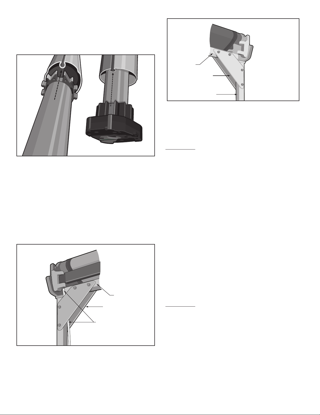
19. Insert the new motor into the roller bar, aligning
the largest slot in the black tube drivers with the
roller bar slot. See Figure 8. Note: If the motor will
not slide into the roller bar, you have selected the
wrong slots.
20. While your helpers support the roller bar, slide
the roller bar toward the end bracket until the motor
makes contact with the end bracket.
21. Attach the motor to the end bracket with the two
¼-20 hex bolts and washers. Be very careful not to
cross-thread the hex bolts, start the bolts by hand
and finish tightening with the 7/16” wrench. The
Open and Close Limit Buttons should be facing up.
22. Position the Motor Cord between the Corner
Braces and the Horizontal square bar. See Figure 9
23. Align the holes in the corner braces with the
Horizontal Square bar and Square Bar Upright and
install the bolts and locknuts removed in Step 14.
Securely tighten all bolts. See Figure 10
24. Use the manual crank wand to slowly roll the
fabric onto the roller bar.
25. Carefully remove the four safety sleeves from
the arm assemblies.
WARNING: THE FOLLOWING PROCEDURE
SHOULD BE ACCOMPLISHED BY FOUR PEOPLE.
26. One person should be positioned at each leg
assembly to prevent the awning from sliding as the
unit is placed in the upright position.
27. One person should be positioned at each end of
the awning assembly, and be able to support and lift
the weight of that end of the awning.
28. When the helpers are in position, the two people
positioned at the ends of the awning assembly
should lift the awning together and tip the unit until
the awning is upright on the leg assemblies.
29. Locate the Cord Cover and position the cover
over the electrical motor cord and flat against the
inside of the square bar upright. Secure in place
with the Velcro straps.
30. Plug the electrical motor cord back into your
ground fault interrupter (GFI) outlet.
WARNING: FAILURE TO PLUG THE ELECTRIC
MOTOR CORD INTO A GROUND FAULT INTER-
RUPTER (GFI) OUTLET CAN RESULT IN PER-
SONAL INJURY.
31. Reset your existing remote transmitter to com-
municate with the new motor using the attached
instructions.
32. Reset the motor stops using the attached
instruction sheet.
33. Test the awning for proper operation.
Rev 3/29/11 ©SunSetter Products, a Massachusetts Limited Partnership, 184 Charles Street, Malden MA 02148
Figure 8
Figure 9
Motor Cord
Horizontal
Square Bar
Corner Braces
Figure 10
Square Bar
Upright
Horizontal
Square Bar
Corner Braces
Resetting the Remote Transmitter
This procedure describes the actions needed to reset the Remote Transmitter that was supplied with your
Motorized awning. This procedure should only be performed if the Remote Transmitter does not operate
the Motorized awning. Please review the steps below to familiarize yourself with the procedure before
attempting to complete them.
1. Verify that the red light on the remote transmitter comes
not come on at all or blinks for less than 5 seconds, you will
section on page 13).
Press the NEUTRAL (middle) button on the transmitter.
2.
Unplug the power cord from the wall.
3.
Insert the wand into the Override crank on the motor and
manually open the awning approximately 3 feet but do not
completely open.
4.
Plug the power cord back into the wall and make sure that
there is electricity available. Let the awning sit for one
minute, undisturbed, without pressing a button on the
remote transmitter or unplugging the cord from the wall.
5.
Unplug the power cord from the wall for 2 seconds.
6.
Plug the power cord back in for 10 seconds.
7.
Unplug the power cord for 2 seconds.
8.
9. Plug the power cord back in and leave it plugged in.
10. When the motor stops, press and hold the programming button on the back of the Remote Transmitter
(see fig. A) for 5 seconds until the motor ‘jogs’, then release. (A ‘jog’ is a short back and forth movement of
the motor).
11. Activate the transmitter by pressing the OPEN and CLOSE buttons at the same time, the motor will jog.
12. Test Direction of motor rotation. The UP arrow must close the Awning. If it does not, hold the "MY" button
until the motor jogs. This reverses the direction of the motor rotation. Test to ensure UP will CLOSE the Awning.
13. Press the programming button on the back of the Remote Transmitter until the motor jogs and release.
NOTE: The motor may rotate approximately 2 feet in one direction and stop.
on when you press and hold the button. If the red light does
need to replace the battery (see Care and Maintenance
NOTE: If the motor does not operate, you will have to clear the OPEN/CLOSE stop settings on the motor.
Complete ONLY steps 1 thru 5 of Appendix A (page 14). After clearing the OPEN/CLOSE stop settings,
verify if transmitter operates the awning. If not, repeat the procedures listed above.
NOTE: Your Remote Transmitter is now reset to operate your Motorized awning. Test the awning for proper
operation. If you cleared the OPEN/CLOSED stop settings on the motor, go to Appendix A on page 14 to reset
them.
Add/Delete a Control Device (Transmitter)
To ADD an additional Control Device (not the one that was supplied with the awning).
• Press the programming button on the back of the transmitter that was supplied with the awning until the
motor ‘jogs’ – see figure A.
• On the additional Control Device, press the programming button until the motor ‘jogs’, then release.
If you wish to DELETE a Control Device, simply repeat the 2 steps listed above.
Resetting the Limit Push Buttons on the SunSetter Motor
Right Side
Top View
Motor
Side View Limit Switches
Awning
See Inset
Yellow
Button for
Open
Position
White
Button for
Closed
Position
Out
In
Figure 15
1. Press the Neutral/Stop button on the remote.
2. Unplug the power cord from the electrical outlet.
3. From a stepladder locate the limit push buttons on the motor. These push buttons will be on the top of
the motor housing under a black plastic protective cap. See Figure 15.
4. Grasp the black protective cap and lift it up. You will notice one yellow button and one white button
inside a recessed area. These are the limit push buttons for the OPEN and CLOSE positions for the
motorized awning.
5. Clear the Factory Settings by separately pressing both buttons (white and yellow) until they are both
‘IN’ or at their lowest point inside the recessed area of the motor housing – see figure 15. You should
practice this a few times to understand this process.
6. Manually crank the awning open to the point where both sets of lateral arms ‘lock’ into the fully
extended position. The fabric will also be at its tightest point.
NOTE: The fabric on the left side (as you face the motor) should be rolling from the bottom of the roller
bar, and the fabric on the right side should be rolling over the top of the roller bar. See Figure 16. If the
fabric is not as noted in figure 16, continue unrolling the fabric until the fabric on the left side is rolling
from the bottom and the fabric on the right side is rolling over the top of the roller bar. Then roll up the
fabric until the fabric becomes tight.
7. Depress the yellow button so that it is in the ‘OUT’ position (or closer to the top of the recessed
area on the motor housing). Now the OPEN position stop is set.
8. Manually roll the awning up until it is almost completely closed. The area to watch for is when the
elbows of the arm assemblies come in contact with the horizontal square bar.
9. Depress the white button so that it is in the ‘OUT’ position (or closer to the top of the recessed area
on the motor housing). Now the CLOSE position stop is set.
10. Replace the black protective cap on the motor housing. Be careful that the cap will not accidentally
depress one of the push limit buttons underneath.
11. Plug the power cord back into the electrical outlet.
12. Test the awning for proper operation.

Other manuals for Oasis

6

Other SunSetter Accessories manuals

SunSetter EASYSHADE Use and care manual

SunSetter

SunSetter EASYSHADE Use and care manual

SunSetter EASYSHADE Use and care manual

SunSetter

SunSetter EASYSHADE Use and care manual

SunSetter 900XT User manual

SunSetter

SunSetter 900XT User manual

SunSetter Motorized PRO Guide

SunSetter

SunSetter Motorized PRO Guide

SunSetter Oasis Use and care manual

SunSetter

SunSetter Oasis Use and care manual

SunSetter Motorized Series Original instructions

SunSetter

SunSetter Motorized Series Original instructions

SunSetter Oasis Guide

SunSetter

SunSetter Oasis Guide

SunSetter Platinum Plus Series Original instructions

SunSetter

SunSetter Platinum Plus Series Original instructions

SunSetter VISTA Original instructions

SunSetter

SunSetter VISTA Original instructions

SunSetter 900XT User manual

SunSetter

SunSetter 900XT User manual

SunSetter EASYSHADE Guide

SunSetter

SunSetter EASYSHADE Guide

SunSetter PRO Operating and safety instructions

SunSetter

SunSetter PRO Operating and safety instructions

SunSetter Vista Series User manual

SunSetter

SunSetter Vista Series User manual

SunSetter OASIS Series User manual

SunSetter

SunSetter OASIS Series User manual

SunSetter Platinum Plus Guide

SunSetter

SunSetter Platinum Plus Guide

SunSetter EASYSHADE Original instructions

SunSetter

SunSetter EASYSHADE Original instructions

SunSetter VISTA Quick start guide

SunSetter

SunSetter VISTA Quick start guide

SunSetter 900XT Installation guide

SunSetter

SunSetter 900XT Installation guide

SunSetter EASYSHADE Use and care manual

SunSetter

SunSetter EASYSHADE Use and care manual

SunSetter Gaviota Quick start guide

SunSetter

SunSetter Gaviota Quick start guide

SunSetter 900XT Use and care manual

SunSetter

SunSetter 900XT Use and care manual

SunSetter VISTA Operating instructions

SunSetter

SunSetter VISTA Operating instructions

SunSetter Oasis Guide

SunSetter

SunSetter Oasis Guide

SunSetter Oasis Guide

SunSetter

SunSetter Oasis Guide

Popular Accessories manuals by other brands

Datalogic Smart-VS Product reference guide

Datalogic

Datalogic Smart-VS Product reference guide

Festo SRBG operating instructions

Festo

Festo SRBG operating instructions

Baxi EXTERNAL SENSOR KIT instruction sheet

Baxi

Baxi EXTERNAL SENSOR KIT instruction sheet

Rice Lake iRite 920i Operation manual

Rice Lake

Rice Lake iRite 920i Operation manual

Stahl SolConeX 8571/11 Series operating instructions

Stahl

Stahl SolConeX 8571/11 Series operating instructions

Climadiff DUOVINO18 use instructions

Climadiff

Climadiff DUOVINO18 use instructions

D+H WRS-S Original instructions

D+H

D+H WRS-S Original instructions

Wenglor OPT2172-74 operating instructions

Wenglor

Wenglor OPT2172-74 operating instructions

Vortice VORTESSENCE DESIGN Instruction booklet

Vortice

Vortice VORTESSENCE DESIGN Instruction booklet

ATI Technologies SR-61 manual

ATI Technologies

ATI Technologies SR-61 manual

Decagon 10HS Operator's manual

Decagon

Decagon 10HS Operator's manual

CAME MR8534 manual

CAME

CAME MR8534 manual

Hunter ET SYSTEM SMARTPORT owner's manual

Hunter

Hunter ET SYSTEM SMARTPORT owner's manual

Ikan ELE-FGK quick start guide

Ikan

Ikan ELE-FGK quick start guide

Vinotemp VT-OUTDR15GD owner's manual

Vinotemp

Vinotemp VT-OUTDR15GD owner's manual

Crestron CT/LC-FPAR1000 user guide

Crestron

Crestron CT/LC-FPAR1000 user guide

Dragino LHT65 user manual

Dragino

Dragino LHT65 user manual

Sierra Monitor Corporation Sentry 5100-28-IT Specification sheet

Sierra Monitor Corporation

Sierra Monitor Corporation Sentry 5100-28-IT Specification sheet

manuals.online logo
manuals.online logoBrands
  • About & Mission
  • Contact us
  • Privacy Policy
  • Terms and Conditions

Copyright 2025 Manuals.Online. All Rights Reserved.