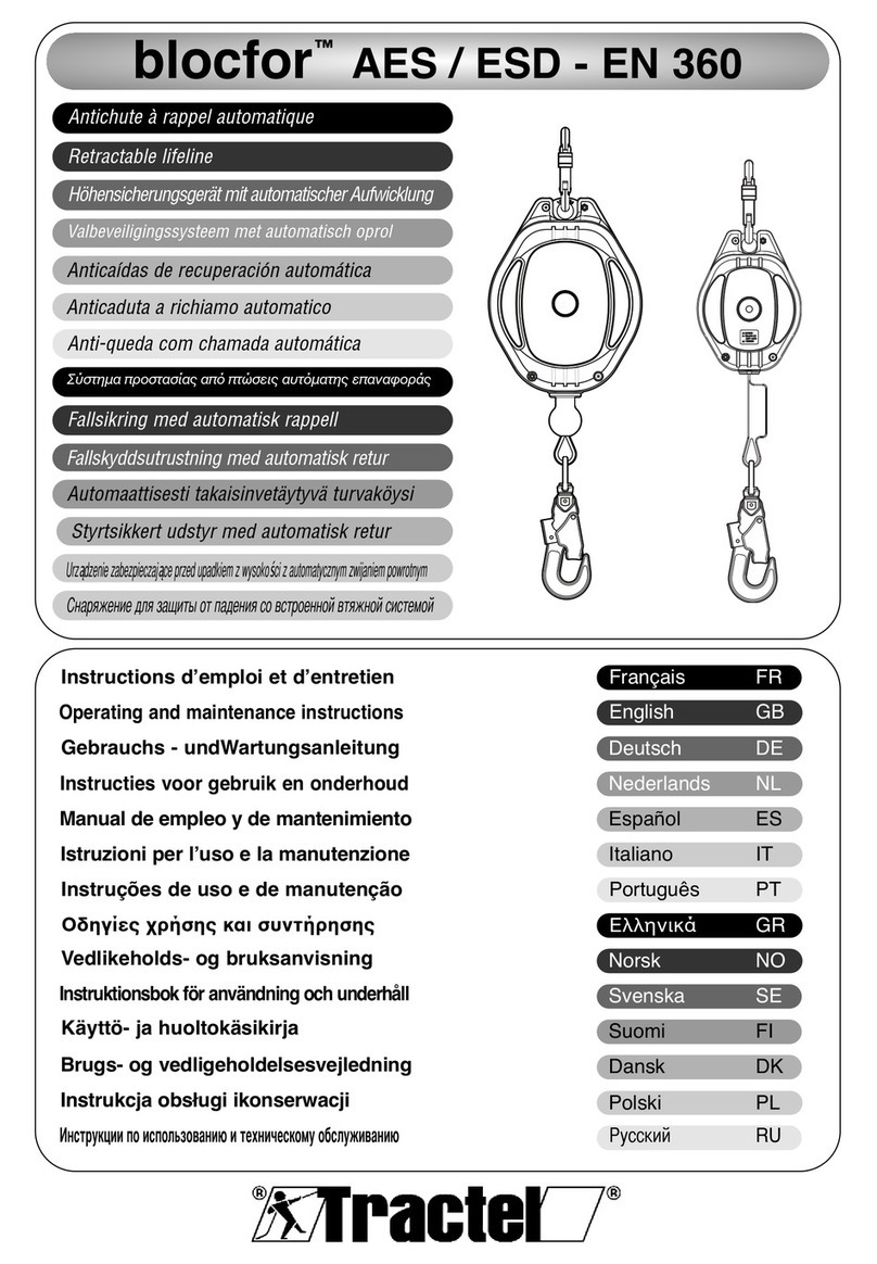
Tractel blocfor ESD Series Operating instructions

GB
FR
DE
NL
ES
IT
PT
GR
NO
SE
FI
DK
PL
RU
blocfor™ESD - EN 360
Operating and maintenance manual English Original manual GB
Manuel d'emploi et d'entretien Français Traduction de la notice originale FR
Installations-, Gebrauchs- und
Wartungsanleitung Deutsch Übersetzung der Originalanleitung DE
Handleiding voor installatie, gebruik en
onderhoud Nederlands Vertaling van de oorspronkelijke handleiding NL
Manual de instalación, utilización y
mantenimiento Español Traducción del manual original ES
Manuale dʼinstallazione, dʼimpiego e di
manutenzione Italiano Traduzione del manuale originale IT
Manual de instalação, de uso e de manutenção Português Tradução do manual original PT
Εγχειρίδιο εγκατάστασης, χρήσης και
συντήρησης Ελληνικά Μετάφραση του πρωτότυπου εγχειριδίου GR
Stallasjons-, bruks- og vedlikeholdshåndbok Norsk Oversettelse av originalanvisning NO
Installations-, bruks- och underhållsanvisning
Svenska Översättning av originalbruksanvisningen SE
Asennus-, käyttö- ja huoltokäsikirja Suomi Alkuperäisen ohjeen käännös FI
Manual for installation, brug og vedligeholdelse Dansk Oversættelse af den originale manuall DK
Instrukcja instalacji, użytkowania i konserwacji Polski Tłumaczenie oryginalnejinstrukcji obsługi PL
Pуководство по установке, использованию и
техническому обслуживанию Русский Перевод инструкции изготовителя RU
Self retracting fall arrester
Antichute à rappel automatique
Höhensicherungsgerät mit automatischer Aufwicklung
Valstop met automatische retour
Anticaídas de recuperación automática
Anticaduta a richiamo automatico
Anti-queda com chamada automática
Ανακόπτης πτώσης αυτόματου επαναφερόμενου τύπου
Fallsikring med automatisk inntrekking
Självindragande fallskyddsutrustning
Automaattisella palautuksella varustettu
putoamisenestolaite
Faldsikring med automatisk rappel
Automatyczny zwijacz zatrzymujący upadki
Устройство защиты втягивающего типа

2

3
GB
Technical specications
Model B1.8A
ESD
B1.8B
ESD
B2
ESD
B5
ESD
B6
ESD
B10
ESD
B10 SR
ESD
B20
ESD
B20 SR
ESD
B30
ESD
B30 SR
ESD
Weight(kg)* 0.98 1.30 1.02 2.17 2.22 4.90 4.07 8.50 7.05 15.70 13.50
Lanyard length
(m)
galvanised steel rope 4.9 mm – – – – – 10 – 19 – 30 –
PE rope – HD 5.5 mm – – – – – – 10 – 18.2 – 30
webbing PES width 46 mm – – 2 – – – – – – – –
webbing PES width 25 mm – – – 5 6 – – – – – –
webbing Aramid + PES width 16 mm 1.8 1.8 – – – – – – – – –
Retraction force (N) 3 to 15 3 to 15 3 to 15 5 to 25 5 to 25 5 to 25 5 to 25 5 to 25 5 to 25 5 to 25 5 to 25
Braking distance (mm) 500 500 400 800 800 800 800 800 800 800 800
Horizontal use OK OK – OK OK OK OK OK OK OK OK
L Min (m) 1 1 – 3 3 3 3 3 3 3 3
M Max (m) 0.5 0.5 – 1.5 1.5 1.5 1.5 1.5 1.5 1.5 1.5
Device securing Anchorage
point Operator Anchorage point
Attaching the retractable lanyard Operator Anchorage
point Operator
* Devices tted with M10 and M47 connectors except model B1.8B ESD tted
with M47 and M51 connectors.
1. General warning
1. Before using your blocfor™ self-retracting fall-
arrester device, and to ensure safe, efcient use of
the harness, it is essential that the user be properly
trained in the use of the equipment and has read
and understood the information given in the manual
supplied by TRACTEL SAS. This manual should be
available at all times to all users. Additional copies
can be supplied on request.
2. Before use, it is essential that users are trained in
the use of this safety device. Check the state of
associated equipment and make sure that there is
adequate room for movement.
3. The blocfor™ self-retracting fall-arrester must only
be used by a single trained and skilled operator, or
by an operator under supervision of a user.
4. Any blocfor™ self-retracting fall-arrester device
which does not appear to be in good condition or
which has already served to stop a fall should be
inspected, with all its associated equipment, by
TRACTEL SAS or by a qualied technician who must
give written authorisation for re-use of the system.
It is recommended to make a visual inspection prior
to each use.
5. Any modication or attachment made to the
equipment cannot be done without prior written
approval from TRACTEL SAS. The equipment must
be transported and stored in its original packaging.
6. Any blocfor™ self-retracting fall-arrester which has
not been inspected over the past 12 months (or in
accordance with the statutory inspection requirement
of the country of use) or which has served to stop a
fall must not be used. They can only be used again
after a new periodical inspection carried out by an
approved and competent technician who can offer
written permission for use. Failing these reviews and
approvals, the blocfor™ self-retracting fall-arrester
will be disassembled and destroyed.
7. The maximum working load for the blocfor™ self-
retracting fall-arrester is 150 kg.
8. If the mass of the operator increased by the weight
of their equipment and tools is between 100 kg
and 150 kg, you must ensure that the total weight
(operator, equipment + tools) does not exceed the
maximum load of each of the components of the fall-
arrest system.
9. This device is suitable for use on an open air site
and for a temperature range of -35°C to +60°C. Avoid
any contact with sharp edges, rough surfaces and
chemical substances.
10. If you are responsible for assigning the equipment
to an employee or similar person, ensure that you
comply with the applicable health and safety at work
regulations.
11. The operator must be physically and mentally t
when using this equipment. In case of doubt, check
with one’s private doctor or with the works doctor. It
is forbidden for use by pregnant women.
12. The equipment should not be used beyond its limits
or in any other situation other than what it has been
designed for (cf. “4. Functions and Description”).
13. The blocfor™ self-retracting fall-arrester systems
should be personally assigned to each operator, in
particular where salaried personnel are concerned.

4
GB
14. Before using a EN 363 fall-arrester device, the user
must ensure that each of the components is in good
working order: security system, locking system.
During installation, no damage should be made to
any of the security functions.
15. In a fall-arrester system, it is essential to verify, prior
to each use, the free space under the operator in
the workplace, to avoid any risk of collision, in the
case of a fall, with the ground or with any obstacle
found in its path.
16. An anti-fall harness is the only body-gripping device
that is permitted for use in a fall-arrester system.
17. It is essential for the safety of the operator that the
device or anchoring point is correctly positioned and
that work is carried out so as to minimise the risk of
falls from height.
18. For the safety of the operator, if the equipment is sold
outside the rst country of destination, the dealer
should supply: an instructions manual, instructions
for maintenance, for periodical inspections and
repairs, all compiled in the language of the country
of use.
NOTE
For any special application, please contact
TRACTEL®.
2. Denitions and pictograms
2.1. Denitions
“User”: Person or department responsible for the
management and safety of use of the product described
in the manual.
“Technician”: Qualied person in charge of the
maintenance operations described in, and authorised
by the user manual, who is competent and familiar with
the product.
“Operator”: Operational personnel involved in the use
of the product as it is intended to be used.
“PPE”: Personal protective equipment against falls from
height.
“Connector”: Connection element between
components of a fall-arrest system. This is EN 362
compliant.
“Fall-arrest harness”: Body harness designed to arrest
falls. It consists of straps and buckles. It features fall-
arrest attachment points marked with an A if they can
be used alone, or marked with A/2 if they are to be used
in combination with another A/2 point. This is EN 361
Standard compliant.
“Self-retracting lifeline”: Fall-arrester with an
automatic locking function and an automatic tensioning
and recoil system for the retractable lanyard.
“Retractable lanyard”: Connecting element of a self-
retracting fall-arrest. It can be wire rope, webbing or
synthetic bres depending on the device type.
“Maximum operating load”: Maximum weight of the
fully dressed operator, equipped with their PPE, work
clothes, tools and components required for the job in
hand.
“Fall-arrest system”: Equipment consisting of following
components:
– Fall-arrest harness.
– Self-retracting lifeline, energy absorber or mobile
fall-arrester on rigid anchor point, or fall-arrester
on exible anchor.
– Anchoring.
– Linking component.
“Fall-arrest system component”: Generic term
dening one of the following:
– Fall-arrest harness.
– Self-retracting lifeline, energy absorber or mobile
fall-arrester on rigid anchor point or fall-arrester
on exible anchor.
– Anchoring.
– Linking component.
2.2. Pictograms
DANGER: Placed at the beginning of the line,
refers to instructions to avoid injury to operators,
including death, serious or minor injuries, and
damage to the environment.
IMPORTANT: Placed at the beginning of the line,
refers to instructions for avoiding a failure or
damage to equipment, but do not directly
endangering the life or health of the operator or that
of others, and/or not likely to cause environmental
damage.
NOTE: Placed at the beginning of the line, refers
to instructions to ensure the effectiveness and
convenience of installation, use or maintenance
operations.
3. Operation
Verication before use (gure3):
• Check the condition of the lanyard along its entire
length (gure3.a):
– the synthetic wire rope or the strap must not show
any signs of abrasion, fraying, burns or cuts.

5
GB
– the metal rope must not show any traces of
bending, scraping, corrosion or broken strands.
• Check that the lanyard locks when you pull sharply
on its end (gure3.b) and that it winds and unwinds
normally along its entire length.
• Check the condition of the casing (no signs of
deformation, screws in place…).
• Check the condition and operation of the connectors:
no signs of deformation, connectors open, close and
lock correctly.
• Check the state of the harness and connector
attachments (gures3.c–3.d). Refer to the specic
manuals for each of the products.
• Check the complete fall-arrester system.
4. Functions and description
Every time before use, check (gure1):
• The blocfor™ self-retracting fall-arrester is a
retractable fall-arrester complying with standard
EN 360. This equipment must only be used by a
single operator equipped with a fall-arresting harness
(EN 361).
• The blocfor™ self-retracting fall-arrester must only
be used for protection of operators against falls when
working at heights.
• The blocfor™ self-retracting fall-arrester must be
secured to an anchor point, with a resistance (R) of
10 kN or more, using its connector. The retractable
lanyard must be connected by its connector to
the dorsal anchor point of the fall-arrest harness
(gure1.b).
• The operator must not exceed a 20° working angle
from the vertical of the anchor point (gure1.c).
• The blocfor™ self-retracting fall-arrester must be
protected against the inltration of any material inside
the housing (paint, sand, mud, etc.).
• Limitations of use (gure1).
• The working load of the blocfor™ self-retracting fall-
arrester is 150 kg. By reference to their respective
manuals, you must make sure before use that all the
components of the fall-arrest system are compatible
with this load. If this is not the case, the maximum load
will be that of the fall-arrest system component with
the lowest maximum load.
• Operating temperature: -35°C to 60°C for blocfor™
self-retracting fall-arresters.
• The blocfor™ can be connected to a temporary
tracpode™ tripod type anchor point (gure1.e).
blocfor™ SR ESD self-retracting fall-arrester
(with synthetic rope):
blocfor™ SR ESD self-retracting fall-arresters
must not be used in an environment where there
is the risk of sparks ying or the risk of a ame
coming into contact with the self-retracting fall-
arrester’s synthetic rope. The melting point of the
synthetic rope is 140°.
blocfor™ R ESD self-retracting fall-arrester:
As well as the self-retracting fall-arrest function, the
blocfor™ R ESD self-retracting fall-arrester has a
recovery function which allows a lifting rescue to
be made. Please refer to the attached instructions
specically for the recovery version: blocfor™ 20R and
30R ESD – EN 360 - EN 1496 class B Self-retracting
fall-arrester with lifting rescue device.
The self-retracting fall-arrest function of the blocfor™ R
ESD device is the same as that on the blocfor™ ESD
self-retracting fall-arrester.
Special case: blocfor™ 1.8A ESD and 1.8B ESD
• The blocfor™ 1.8A ESD self-retracting fall-arrester
(gure5.a) must be secured to an anchor point, with a
resistance (R) of 10 kN or more, using the connector
located at the top of the device. The M47 connector
secured at the end of the energy absorber of the
retractable lanyard must always be connected to the
fall-arrester harness anchor point.
Any other combination in use is dangerous and
prohibited.
• The blocfor™ 1.8B ESD self-retracting fall-arrester
(gure5.b) must be connected using its M47 connector
attached at the end of the energy absorber to the fall-
arrester harness anchor point. The connector at the
end of the retractable lanyard must be connected to
an anchor point with a resistance (R) anchor of 10 kN
or more.
Any other combination in use is dangerous and
prohibited.
Horizontal use:
blocfor™ self-retracting fall-arresters, with the exception
of blocfor™ 2 ESD, have been tested in horizontal use
in accordance with European spec. CNB/P/11.060
October 2014, according to the type A on edge radius
min. 0.5 mm: seetechnicalspecicationtableabove.
Horizontal use is prohibited for blocfor™ 2 ESD.
Only blocfor™ 5 ESD, blocfor™ 6 ESD, blocfor™
10 ESD, blocfor™ 20 ESD, blocfor™ 30 ESD,
blocfor™ 1.8A ESD and blocfor™ 1.8B ESD are
certied for horizontal use.
If the arrest is considered to be cutting, or if there
is a sharp edge present, take all possible
precautions to avoid a fall and use edge protection
where this isn’t possible.
Before using the blocfor™ self-retracting fall-arrester,
check (gures1.dand1.f):
– Check that the blocfor™ self-retracting fall-arrester
anchor point is located at the same height or above
the edge.

6
GB
– Check that the angle formed by the lanyard in contact
with the edge, in the event of a fall, is less than 90°
(gure1.fbis).
– The distance between the anchor point of the
blocfor™ self-retracting fall-arrester device and
the edge (L min) must conform with the technical
specications in table above (gure1.f).
– To reduce the risk of swinging, the movement of the
operator is limited to a maximum distance of lateral
displacement perpendicular to the edge (Max M)
which must conform with the technical specication
table above (gure1.d).
– That there is no obstacle under the suspension /
swing area in the event of a fall.
– Check that a specic rescue plan has been set up in
the event of a fall.
– That the roofs do not show any possibility of weakness
(bro-cement, etc.) if in any doubt, install a solid path
of movement compatible with the roof.
– There are other possible cases that are not included
in this list. There are numerous other possibilities that
we cannot either list or foresee. In the event of doubt
or misunderstanding of this manual please contact
Tractel®for further information.
Note: the blocfor™ self-retracting fall-arrester in
horizontal use has not been tested in combination with
a lifeline compliant with EN 795 Class C.
5. Operating principle
blocfor™ self-retracting fall-arrester ESD:
In the event of a fall, the mechanism located inside the
blocfor™ self-retracting fall-arrester instantaneously
locks by means of a ratchet system and the fall is
stopped gently by a tear-type energy absorber with
a stop value of less than 6 kN. When climbing and/
or descending, the lanyard operator is maintained
tensioned by the return spring.
In addition the blocfor™ ESD automatic retraction fall
arrester is tted with a safety system guaranteeing that
the fall of an operator is stopped in all safety even if the
fall occurs when the strap or the rope has completely
come out of the blocfor™ ESD automatic retraction fall
arrester.
blocfor™ R ESD self-retracting fall-arrester:
The operating principle of the recovery function is
detailed in the attached instructions specic to the
blocfor™ 20R and 30R ESD – EN 360 - EN 1496
class B Self-retracting fall-arrester with lifting rescue
device §5.
6. Clearance
6.1. Vertical use
The air clearance H (gure1.g) is the free space under
the feet of the operator. It is dened by the formula:
H = 3 m + Hp
which breaks down as follows:
3 m = height of fall with the blocfor™ self-retracting fall-
arrester: 2 metres + 1 meter security.
Hp = maximum deection of the anchor point dened in
the instructions for use of the anchor point.
6.2. Horizontal use
The vertical clearance H (gure 1.h) is the free space
below the operator during horizontal use. This is
dened by the formula below:
H = 4 m + Hp
which breaks down as follows:
4 m = fall height with the blocfor™ automatic retraction
fall arrester in horizontal use: 3 metres + 1 metre for
additional safety.
Hp = the maximum anchor point deexion as dened in
the anchor point usage manual.
7. Prohibited use
Figure2.
It is strictly forbidden:
• to install or use the blocfor™ self-retracting fall-
arrester without rst having been authorised, trained
and recognised to be qualied in the use of the device,
or otherwise, without the supervision of an authorised
operator, trained and recognised to be qualied in use
of the device.
• to use the blocfor™ self-retracting fall-arrester if any
of the markings are not legible.
• to install or use the blocfor™ self-retracting fall-
arrester without rst having carried out the preliminary
checks.
• to use a blocfor™ self-retracting fall-arrester which
has not been covered by a periodical inspection over
the past 12 months by a technician having authorised
re-use in writing.
• to connect the blocfor™ self-retracting fall-arrester to
a point which has not been covered by a periodical
inspection over the past 12 months by a qualied
technician having authorised re-use in writing.

7
GB
• to use the blocfor™ self-retracting fall-arrester for
any other application other than for automatic fall
protection of operators.
• to secure the blocfor™ self-retracting fall-arrester by
any other means other than its anchor point.
• to use the blocfor™ self-retracting fall-arrester in
contradiction with the information specied in the
section “15. Life cycle”.
• to use the blocfor™ self-retracting fall-arrester as a fall
protection system for more than 1 operator.
• to use the blocfor™ self-retracting fall-arrester by
an operator whose weight, equipment included, is
greater than 150 kg.
• To use the blocfor™ self-retracting fall-arrester with a
load of between 100 kg and 150 kg (total weight of
the operator, equipment and tools) if any component
in the fall-arrest system has a lower maximum load.
• to use the blocfor™ self-retracting fall-arrester if it has
served to stop a fall.
• to use the blocfor™ self-retracting fall-arrester as a
means of suspension or to hold a work position.
• to use the blocfor™ self-retracting fall-arrester in a
highly corrosive or explosive atmosphere.
• to use the blocfor™ self-retracting fall-arrester outside
the temperature range specied in this manual.
• to use the blocfor™ self-retracting fall-arrester if the
fall clearance is not sufcient with respect to a falling
operator.
• to use the blocfor™ self-retracting fall-arrester if
any obstacle is located along the fall path or on the
swinging path when used in a horizontal congu ration.
• to use the blocfor™ self-retracting fall-arrester if you
are not in good physical condition.
• to use the blocfor™ self-retracting fall-arrester if you
are pregnant.
• to use the blocfor™ self-retracting fall-arrester if
the safety function of any of the associated items is
affected by the safety function of another item or may
interfere with it.
• to use the blocfor™ self-retracting fall-arrester if
the fall indicator on the M46 connector is activated
(gure3.d).
• to release the blocfor™ self-retracting fall-arrester
lanyard if it not is entirely wound in (gure 2.a).
• to use the blocfor™ self-retracting fall-arrester to
secure a materials load.
• to secure the blocfor™ self-retracting fall-arrester to
a structural anchor point with a strength less than
10 kN, or which may be assumed as such.
• to use the blocfor™ self-retracting fall-arrester for
vertical angles of over 20° (gure1.c).
• to use the blocfor™ self-retracting fall-arrester lanyard
as a means of slinging.
• to interfere with the alignment of the blocfor™ self-
retracting fall-arrester with respect to the lanyard.
• to interfere with free unwinding and winding of the
blocfor™ self-retracting fall-arrester lanyard.
• to perform any repair or maintenance operations
on the blocfor™ self-retracting fall-arrester without
rst having been trained and qualied, in writing, by
TRACTEL®(gure2.b).
• to use the blocfor™ self-retracting fall-arrester if it is
not complete, if it has been dismantled beforehand or
if components have been replaced by any person not
unauthorised by TRACTEL®.
• to use the blocfor™ self-retracting fall-arrester
horizontally if the radius of the edge (R Min) does not
comply with the technical specications table above,
or if there is presence of burrs.
• to use the blocfor™ self-retracting fall-arrester
horizontally if the distance between the anchor
point and the edge (L min) does not comply with the
technical specications table above.
• to use the blocfor™ self-retracting fall-arrester
horizontally if the maximum lateral displacement
distance perpendicular to the edge (M max) does not
comply with the technical specications table above.
• to use the blocfor™ self-retracting fall-arrester in a
horizontal conguration if a specic rescue plan has
not been set up beforehand.
• to use the blocfor™ 2 ESD self-retracting fall-arrester
in a horizontal conguration.
• to use the blocfor™ 1.8A ESD self-retracting fall-
arrester if the M47 connector secured to the end
of the energy absorber of the retractable lanyard
is connected to an anchor point, and if the upper
connector of the device is linked to an anchor point on
the fall-arrester harness.
• to use the blocfor™ 1.8B ESD self-retracting fall-
arrester if the M47 connector secured to the end
of the energy absorber of the retractable lanyard is
connected to an anchor point, and if the retractable
lanyard connector is linked to an anchor point on the
fall-arrester harness.
• to use the blocfor™ SR ESD self-retracting fall-
arrester in an environment where there is the risk of
sparks ying or the risk of a ame coming into contact
with the self-retracting fall-arrester’s synthetic rope.
8. Installation
• Insofar as possible, the structural anchorage point
should be located above the operator. The structural
anchor point must withhold a minimal resistance of
10 kN.
• The connection to the anchoring point or to the
structure must be done using an EN 362 connector.
• For the connection of the fall-arrest system to the fall-
arrest harness, refer to the instructions of the harness
and the fall-arrest system in order to use the proper
anchorage point and the proper attaching procedure.
blocfor™ R ESD self-retracting fall-arrester:
Please refer to the attached instructions specic to the
blocfor™ 20R and
30R ESD – EN 360 - EN 1496 class B Self-retracting
fall-arrester with lifting rescue device.

8
GB
DANGER
Before and during use, it is necessary to plan out
how possible rescue can be efciently and safely
conducted, within less than 15 minutes. Beyond this
time, operator is in danger.
9. Components and materials
• Steel Ropes: galvanised or stainless steel.
• Synthetic rope: PE HD.
• Webbing strap: PES, Aramid + PES.
• Energy absorber: PA + PES.
• Housings: PA/ABS.
• Fastening parts: Stainless steel and zinc-plated steel.
10. Associated equipment
Fall-arrester system (EN 363):
• An anchorage (EN 795).
• An end connector (EN 362).
• A fall-arrest system (EN 360).
• A connector (EN 362).
• A descender (EN 361).
11. Maintenance and storage
If your blocfor™ self-retracting fall-arrester is dirty,
it can be washed with clear, cold water using a mild
detergent for fabrics, and a synthetic brush.
If during use or when washing, the blocfor™ self-
retracting fall-arrester becomes wet, allow it to dry
naturally in a shaded location away from any source
of heat.
During transport and storage, protect the equipment in
a moisture-free package against any danger (source of
direct heat, chemical products, UV radiation, etc.).
Figure4.
12. Equipment compliance
TRACTEL SAS RD 619 – Saint-Hilaire-sous-Romilly
– F-10102 Romilly-sur-Seine France hereby declares
that the safety equipment described in this manual,
• complies with the requirements of European Directive
89/686/EEC of December 1989.
• is identical to the PPE, having been subject to the
“CE”-type-examination certicate issued by the
APAVE SUDEUROPE SAS – CS 60193 – 13322
Marseille – France, identied under the number 0082,
and tested according to the 2002 EN 360 standard.
• is subject to the procedure referred to in Art. 11B of
Directive 89/686/EEC, under the control of a notied
body: APAVE SUDEUROPE SAS – CS 60193 – 13322
Marseille – France, identied under the number 0082.
13. Marking
Name of product:
B X ESD Y-Z
B: for the name blocfor™
X: the type of blocfor™ within the range (1.8A, 1.8B,
2, 5, 6,...)
ESD: generic term for the range
Y: Connector model: device
Z: Connector model: retractable lanyard
Example:
B10 ESD M10-M47
blocfor™ self-retracting fall-arrester from the ESD
range, type 10, tted with a model M10 connector
on the device and a model M47 connector on the
retractable lanyard.
The label on each blocfor™ self-retracting fall-arrester
indicates:
a. The trade name: TRACTEL®,
b: The name of the product,
c: The reference standard followed by the year of
application,
d: The product reference: eg: 010642,
e. CE Logo followed by the number 0082, identication
number of the approved body responsible for
production control,
f. Year and week of manufacture,
g. The serial number,
h. A pictogram showing that the manual must be read
before use,
w. Maximum operating load,
aa. Date of the next periodic review,
ab. Minimum strength of anchor point.
14. Periodic inspection and repair
An annual periodical inspection is required, but
depending on the frequency of use, environmental
conditions and regulations of the company or the
country of use, periodical inspections may be more
frequent.

9
GB
Periodical inspections shall be carried out by an
approved and competent technician and in accordance
with the manufacturer’s examination procedures as laid
down in the le “Verication procedures for TRACTEL®
PPE”.
Verication of the legibility of the marking on the product
is an integral part of the periodical inspection.
Following the periodical inspection, a certicate of
return to service must issued by the approved and
competent technician who performed the periodical
inspection. This return to service must be recorded on
the inspection sheet in the middle of this manual. This
inspection sheet should be retained throughout the life
of the product until it is scrapped.
After arresting a fall, this product must undergo a
periodical inspection, as described in these instructions.
Any textile components of the product must be replaced,
even if they do not display any visible alteration.
15. Lifespan
TRACTEL®textile PPE equipments as harnesses,
lanyards, ropes and energy absorbers, TRACTEL®
Mechanical PPE equipments as stopcable™ and
stopfor™ fall-arresters, blocfor™ self-retracting fall-
arresters, and the TRACTEL®lifelines can be used
without restrictions from their manufacturing date
providing that:
– A normal use is made in accordance with the
instructions manual,
– A periodical inspection, which must be accomplished
at least once a year by an approved and competent
technician. At the end of this periodical inspection, the
PPE must be certied t to return to service, in writing,
– Instructions manual procedures for storage and
transport are strictly met.
16. Disposal
When disposing of the product, all components must
be recycled with preliminary sorting of components
into metallic and synthetic materials. These materials
must be recycled by specialist bodies. During disposal,
dismantling to separate components should be
achieved by a duly trained person.

10
FR
Spécications techniques
Modèle B1.8A
ESD
B1.8B
ESD
B2
ESD
B5
ESD
B6
ESD
B10
ESD
B10 SR
ESD
B20
ESD
B20 SR
ESD
B30
ESD
B30 SR
ESD
Poids (kg)* 0.98 1.30 1.02 2.17 2.22 4.90 4.07 8.50 7.05 15.70 13.50
Longueur de longe
(m)
câble acier galvanisé 4.9 mm – – – – – 10 – 19 – 30 –
câble PE - HD 5.5 mm – – – – – – 10 – 18.2 – 30
sangle PES largeur 46 mm – – 2 – – – – – – – –
sangle PES largeur 25 mm – – – 5 6 – – – – – –
sangle Aramide + PES largeur 16 mm 1.8 1.8 – – – – – – – – –
Force de rappel (N) 3 à 15 3 à 15 3 à 15 5 à 25 5 à 25 5 à 25 5 à 25 5 à 25 5 à 25 5 à 25 5 à 25
Distance de freinage (mm) 500 500 400 800 800 800 800 800 800 800 800
Usage horizontal OK OK – OK OK OK OK OK OK OK OK
L Min (m) 1 1 – 3 3 3 3 3 3 3 3
M Max (m) 0.5 0.5 – 1.5 1.5 1.5 1.5 1.5 1.5 1.5 1.5
Accrochage appareil Point
d'ancrage Opérateur Point d’ancrage
Accrochage longe rétractable Opérateur Point
d'ancrage Opérateur
1. Consignes prioritaires
1. Avant d’utiliser un antichute à rappel automatique
blocfor™, il est indispensable pour la sécurité
d’emploi du matériel et son efcacité que l’utilisateur
lise et comprenne les informations dans la notice
fournie par TRACTEL SAS. Cette notice doit être
conservée à disposition de tout utilisateur. Des
exemplaires supplémentaires peuvent être fournis
sur demande.
2. Avant d’utiliser ce matériel de sécurité il est
indispensable d’avoir reçu une formation à son
emploi. Vérier l’état des équipements associés et
assurez-vous que le tirant d’air est sufsant.
3. L’antichute à rappel automatique blocfor™ ne peut
être utilisé que par un seul opérateur formé et
compétent ou par un opérateur sous la surveillance
d’un utilisateur.
4. Si un antichute à rappel automatique blocfor™ n’est
pas en bon état apparent ou s’il a servi à l’arrêt d’une
chute, l’ensemble de l’équipement doit être vérié
par TRACTEL SAS ou par un technicien habilité et
compétent qui doit autoriser par écrit la réutilisation
du système. Un contrôle visuel avant chaque
utilisation est recommandé.
5. Toute modication ou adjonction à l’équipement
ne peut se faire sans l’accord préalable écrit de
TRACTEL SAS. L’équipement doit être transporté et
stocké dans son emballage d’origine.
6. Tout antichute à rappel automatique blocfor™
n’ayant pas fait l’objet d’un examen périodique au
cours des douze derniers mois (ou conformément
aux exigences d’inspection réglementaire du pays
d’utilisation) ou ayant arrêté une chute, ne doit pas
être utilisé. Il ne pourra être utilisé de nouveau
qu’après un nouvel examen périodique réalisé par
un technicien habilité et compétent qui autorisera
par écrit son utilisation. À défaut de ces examen
et autorisation, l’antichute à rappel automatique
blocfor™ sera réformé et détruit.
7. La charge maximale d’utilisation est de 150 kg pour
l’antichute à rappel automatique blocfor™.
8. Si la masse de l’opérateur augmentée de la masse
de son équipement et de son outillage est comprise
entre 100 kg et 150 kg, il est impératif de s’assurer
que cette masse totale (opérateur + équipement
+ outillage) n’excède pas la charge maximale
d’utilisation de chacun des éléments constituant le
système d’arrêt des chutes.
9. Cet équipement convient pour une utilisation sur
chantier à l’air libre et pour une plage de température
comprise entre -35°C et +60°C. Éviter tout contact
avec des arêtes vives, des surfaces abrasives, des
produits chimiques.
10. Si vous devez coner le matériel à un personnel
salarié ou assimilé, conformez-vous à la
réglementation du travail applicable.
11. L’opérateur doit être en pleine forme physique et
psychologique lors de l’utilisation de cet équipement.
En cas de doute, consulter son médecin ou le
médecin du travail. Interdit aux femmes enceintes.
12. L’équipement ne doit pas être utilisé au-delà de
ses limites, ou dans toute autre situation que celle
pour laquelle il est prévu : cf. « 4. Fonctions et
description ».
13. Il est recommandé d’attribuer personnellement
l’antichute à rappel automatique blocfor™ à chaque
opérateur, notamment s’il s’agit de personnel salarié.
* Appareils équipés des connecteurs M10 et M47 sauf le modèle B1.8B ESD
équipé des connecteurs M47 et M51.

11
FR
14. Avant l’utilisation d’un système d’arrêt des chutes
EN 363, l’utilisateur doit s’assurer que chacun des
composants est en bon état de fonctionnement :
système de sécurité, verrouillage. Lors de la mise
en place, il ne doit pas y avoir de dégradation des
fonctions de sécurité.
15. Dans un système d’arrêt des chutes, il est essentiel
de vérier l’espace libre sous l’opérateur sur le lieu
de travail avant chaque utilisation, de manière qu’en
cas de chute il n’y ait pas de risque de collision avec
le sol ni présence d’un obstacle sur la trajectoire
de la chute.
16. Un harnais d’antichute est le seul dispositif de
préhension du corps qu’il est permis d’utiliser dans
un système d’arrêt des chutes.
17. Il est essentiel pour la sécurité de l’opérateur que
le dispositif ou le point d’ancrage soit correctement
positionné et que le travail soit effectué de manière
à réduire au minimum le risque de chutes ainsi que
sa hauteur.
18. Pour la sécurité de l’opérateur, si le produit est
revendu hors du premier pays de destination, le
revendeur doit fournir : un mode d’emploi, des
instructions pour l’entretien, pour les examens
périodiques et les réparations, rédigés dans la
langue du pays d’utilisation du produit.
NOTE
Pour toute application spéciale, n’hésitez pas à
vous adresser à TRACTEL®.
2. Dénitions et pictogrammes
2.1. Dénitions
« Utilisateur » : Personne ou service responsable de
la gestion et de la sécurité d’utilisation du produit décrit
dans le manuel.
« Technicien » : Personne qualiée, en charge des
opérations de maintenance décrites et permises
à l’utilisateur par le manuel, qui est compétente et
familière avec le produit.
« Opérateur » : Personne opérant dans l’utilisation du
produit conformément à la destination de celui-ci.
« EPI » : Équipements de protection individuelle contre
les chutes de hauteur.
« Connecteur » : Élément de connexion entre
composants d’un système d’arrêt des chutes. Il est
conforme à la norme EN 362.
« Harnais d’antichute » : Dispositif de préhension
du corps destiné à arrêter les chutes. Il est constitué
de sangles et bouclerie. Il comporte des points
d’accrochage antichute marqués d’un A s’ils peuvent
être utilisés seuls, ou marqués d’un A/2 s’ils doivent
être utilisés en combinaison avec un autre point A/2. Il
est conforme à la norme EN 361.
« Antichute à rappel automatique » : Antichute avec
une fonction de blocage automatique et un système
automatique de tension et de rappel pour la longe
rétractable.
« Longe rétractable » : Élément de connexion d’un
antichute à rappel automatique. Elle peut être en câble
métallique, en sangle ou en bres synthétiques selon
le type d’appareil.
« Charge maximale d’utilisation » : Masse maximale
de l’opérateur habillé, équipé de ses EPI, de sa tenue
de travail, de son outillage et des composants dont il a
besoin pour faire son intervention.
« Système d’arrêt des chutes » : Ensemble composé
des éléments suivants :
– Harnais d’antichute.
– Antichute à rappel automatique ou absorbeur
d’énergie ou antichute mobile sur support
d’assurage rigide ou antichute mobile sur support
d’assurage exible.
– Ancrage.
– Élément de liaison.
« Élément du système d’arrêt des chutes » : Terme
générique dénissant l’un des éléments suivants :
– Harnais d’antichute.
– Antichute à rappel automatique ou absorbeur
d’énergie ou antichute mobile sur support
d’assurage rigide ou antichute mobile sur support
d’assurage exible.
– Ancrage.
– Élément de liaison.
2.2. Pictogrammes
DANGER : Placé en début de ligne, désigne des
instructions destinées à éviter des dommages aux
opérateurs, notamment les blessures mortelles,
graves ou légères, ainsi que les dommages à
l’environnement.
IMPORTANT : Placé en début de ligne, désigne
des instructions destinées à éviter une défaillance
ou un dommage des équipements, mais ne mettant
pas directement en danger la vie ou la santé de
l’opérateur ou celles d’autres personnes, et/ou
n’étant pas susceptible de causer de dommage à
l’environnement.

12
FR
NOTE : Placé en début de ligne, désigne des
instructions destinées à assurer l’efcacité ou la
commodité d’une installation, d’une utilisation ou
d’une opération de maintenance.
3. Conditions d’utilisation
Vérication avant utilisation (gure3) :
• Vérier l’état de la longe sur toute sa longueur
(gure3.a) :
– le câble synthétique ou la sangle ne doivent pas
présenter de traces d’abrasion, d’eflochage, de
brûlures, de coupures.
– le câble métallique ne doit pas présenter de traces
de pliure, d’abrasion, de corrosion, de ls coupés.
• Vérier que la longe se bloque lorsque l’on tire
sèchement sur son extrémité (gure 3.b) et qu’elle
s’enroule et se déroule normalement sur toute sa
longueur.
• Vérier l’état du carter (pas de déformation, présence
des vis...).
• Vérier l’état et le fonctionnement des connecteurs :
pas de déformation visible, ouverture, fermeture et
verrouillage possibles.
• Vérier l’état des composants associés harnais et
connecteurs (gures 3.c – 3.d). Se reporter aux
notices spéciques de chacun des produits.
• Vérier le système d’arrêt des chutes complet.
4. Fonctions et description
Recommandations d’utilisation (gure1) :
• L’antichute à rappel automatique blocfor™ est un
antichute à rappel automatique, conforme à la norme
EN 360. Cet équipement ne peut être utilisé que par
un seul opérateur équipé d’un harnais d’antichute
(EN 361).
• L’antichute à rappel automatique blocfor™ doit être
exclusivement utilisé pour la protection de l’opérateur
contre les chutes de hauteur.
• L’antichute à rappel automatique blocfor™ doit être
relié à un point d’ancrage, de résistance R supérieure
ou égale à 10 kN, par son connecteur. La longe
rétractable doit être reliée par son connecteur au
point d’accrochage dorsal du harnais d’antichute
(gure1.b).
• L’opérateur ne dépassera pas un angle de travail
de 20° par rapport à la verticale du point d’ancrage
(gure1.c).
• L’antichute à rappel automatique blocfor™ doit être
protégé contre l’introduction de produit à l’intérieur du
carter (peinture, sable, boue...).
• Limites d’utilisation (gure1).
• La charge maximale d’utilisation de l’antichute à rappel
automatique blocfor™ est de 150 kg. Il est impératif de
s’assurer, avant utilisation, que tous les éléments du
système d’arrêt des chutes sont compatibles avec cette
charge en se référant à leurs notices respectives. Si
ce n’est pas le cas, la charge maximale sera celle de
l’élément du système d’arrêt des chutes qui a la plus
faible charge maximale d’utilisation.
• Température d’utilisation : -35°C à 60°C pour
l’antichute à rappel automatique blocfor™.
• Le blocfor™ peut être connecté à un point d’ancrage
temporaire de type trépied tracpode™ (gure1.e).
Antichute à rappel automatique blocfor™ SR ESD
(avec câble synthétique) :
Les antichutes à rappel automatique blocfor™SR
ESD ne doivent pas être utilisés dans un
environnement dans lequel il y a : risque de
projections d’étincelles, risque de contact d’une
amme avec le câble synthétique de l’antichute à
rappel automatique. Le point de fusion du câble
synthétique est de 140°.
Antichute à rappel automatique blocfor™ R ESD :
L’antichute à rappel automatique blocfor™ R ESD
possède, en plus de la fonction antichute à rappel
automatique, une fonction récupérateur qui permet
de réaliser du sauvetage par élévation. Voir la notice
spécique jointe pour la version récupérateur :
blocfor™ 20R et 30R ESD – EN 360 - EN 1496 classe
B Antichute à rappel automatique avec dispositif de
sauvetage par élévation.
La fonction antichute à rappel automatique de l’appareil
blocfor™ R ESD est la même que sur l’appareil
antichute à rappel automatique blocfor™ ESD.
Cas particulier : blocfor™ 1.8A ESD et 1.8B ESD
• L’antichute à rappel automatique blocfor™1.8A ESD
(gure5.a) doit impérativement être relié à un point
d’ancrage de résistance R supérieure ou égale à
10 kN par le connecteur situé en haut de l’appareil.
Le connecteur M47 xé en extrémité du dissipateur
d’énergie de la longe rétractable doit impérativement
être relié au point d’accrochage du harnais d’antichute.
Toute autre combinaison d’utilisation est
dangereuse et interdite.
• L’antichute à rappel automatique blocfor™ 1.8B ESD
(gure5.b) doit impérativement être relié par son
connecteur M47 xé en extrémité du dissipateur
d’énergie au point d’accrochage du harnais
d’antichute. Le connecteur en extrémité de la longe
rétractable doit être relié à un point d’ancrage de
résistance R supérieure ou égale à 10 kN.
Toute autre combinaison d’utilisation est
dangereuse et interdite.
Usage horizontal :
Les antichutes à rappel automatique blocfor™,
à l’exception du blocfor™ 2 ESD, ont été testés
en usage horizontal suivant la che européenne
CNB/P/11.060 d’octobre 2014 selon le type A sur arête
de rayon 0.5 mm mini : voirtableaudesspécications
techniquesci-dessus.

13
FR
L’usage horizontal est interdit pour le blocfor™ 2
ESD. Seuls les blocfor™ 5 ESD, blocfor™ 6 ESD,
blocfor™ 10 ESD, blocfor™ 20 ESD, blocfor™
30 ESD, blocfor™ 1.8A ESD et blocfor™
1.8B ESD sont certiés pour l’usage horizontal.
Si l’arête est considérée coupante ou s’il y a
présence de bavure, prendre toutes les mesures
nécessaires pour éviter une éventuelle chute et
utiliser une protection d’arête lorsque ce n’est pas
possible.
Avant toute utilisation de l’antichute à rappel
automatique blocfor™ en usage horizontal, vérier que
(gures1.det1.f) :
– Le point d’ancrage de l’antichute à rappel automatique
blocfor™ est situé à la même hauteur ou au-dessus
de l’arête.
– L’angle formé par la longe en contact avec l’arête s’il y
a chute est au moins de 90° (gure1.fbis).
– La distance entre le point d’ancrage de l’antichute
à rappel automatique blocfor™ et l’arête (L mini)
doit être conforme au tableau des spécications
techniques ci-dessus (gure1.f).
– Pour atténuer le risque de pendulage, le déplacement
de l’opérateur est limité à une distance maximale de
déplacement latéral à la perpendiculaire de l’arête
(M Max) qui doit être conforme au tableau des
spécications techniques ci-dessus (gure1.d).
– Qu’il n’y a aucun obstacle sur la trajectoire de
pendulage lors d’une chute.
– Qu’un plan de sauvetage spécique a été mis en
place s’il y a chute.
– Qu’il n’y a pas de risque de fragilité de la toiture (type
bro-ciment, ...). En cas de doute, mettre en place un
chemin de circulation solide et compatible avec la toiture.
– D’autres cas de gure ne sont pas énumérés dans
cette liste. Une multitude d’autres cas de gure
existent que nous ne pouvons énumérer, ni imaginer.
En cas de doute ou d’incompréhension de la présente
notice, renseignez-vous auprès de Tractel®.
Remarque : l’antichute à rappel automatique
blocfor™ en usage horizontal n’a pas été testé en
combinaison avec une ligne de vie conforme à l’EN
795 classe C.
5. Principe de fonctionnement
Antichute à rappel automatique blocfor™ ESD :
En cas de chute, le mécanisme situé à l’intérieur de
l’antichute à rappel automatique blocfor™ se bloque
instantanément grâce à un système de cliquet et l’arrêt
de la chute s’effectue en douceur grâce à un principe
d’absorbeur d’énergie à déchirure avec une valeur
d’arrêt inférieure à 6 kN. Lors de l’ascension et/ou de
la descente de l’opérateur, la longe est maintenue en
tension grâce au ressort de rappel.
De plus l’antichute à rappel automatique blocfor™ ESD
est équipé d’un système de sécurité garantissant l’arrêt
de l’opérateur dans des conditions de sécurité, même
si la chute intervient lorsque la sangle ou le câble sont
totalement sortis de l’antichute à rappel automatique
blocfor™ ESD.
Antichute à rappel automatique blocfor™ R ESD :
Le principe de fonctionnement de la fonction
récupérateur est détaillé dans la notice spécique jointe
blocfor™ 20R et 30R ESD – EN 360 - EN 1496 classe
B Antichute à rappel automatique avec dispositif de
sauvetage par élévation §5.
6. Tirant d’air
6.1. Usage vertical
Le tirant d’air H (gure 1.g) est l’espace libre sous
les pieds de l’opérateur. Il est déni par la formule ci-
dessous :
H = 3 m + Hp
qui se décompose comme suit :
3 m = hauteur de chute avec l’antichute à rappel
automatique blocfor™ : 2 mètres + 1 mètre de sécurité.
Hp = déexion maximale du point d’ancrage dénie
dans la notice d’utilisation du point d’ancrage.
6.2. Usage horizontal
Le tirant d’air H (gure1.h) est l’espace libre sous les
pieds de l’opérateur en usage horizontal. Il est déni
par la formule ci-dessous :
H = 4 m + Hp
qui se décompose comme suit :
4 m = hauteur de chute avec l’antichute à rappel
automatique blocfor™ en usage horizontal : 3 mètres
+ 1 mètre de sécurité.
Hp = déexion maximale du point d’ancrage dénie
dans la notice d’utilisation du point d’ancrage.
7. Contre-indications d’emploi
Figure2.
Il est strictement interdit :
• d’installer ou d’utiliser l’antichute à rappel
automatique blocfor™ sans y avoir été autorisé,
formé et reconnu compétent ou à défaut, sans être
sous la surveillance d’un opérateur autorisé, formé et
reconnu compétent.
• d’utiliser l’antichute à rappel automatique blocfor™ si
son marquage n’est pas lisible.
• d’installer ou d’utiliser l’antichute à rappel automatique
blocfor™ n’ayant pas fait l’objet des vérications
préalables.
• d’utiliser l’antichute à rappel automatique blocfor™
qui n’a pas fait l’objet d’un examen périodique, depuis

14
FR
moins de 12 mois, par un technicien ayant autorisé sa
réutilisation par écrit.
• de connecter l’antichute à rappel automatique
blocfor™ à un point qui n’a pas fait l’objet d’un
examen périodique, depuis moins de 12 mois, par un
technicien ayant autorisé sa réutilisation par écrit.
• d’utiliser l’antichute à rappel automatique blocfor™
pour toute autre application que celle d’antichute à
rappel automatique de l’opérateur.
• de xer l’antichute à rappel automatique blocfor™ par
tout autre moyen que son point d’ancrage.
• d’utiliser l’antichute à rappel automatique blocfor™ en
contradiction avec les informations dénies dans le
paragraphe « 15. Durée de vie ».
• d’utiliser l’antichute à rappel automatique blocfor™
comme protection antichute de plus de 1 opérateur.
• d’utiliser l’antichute à rappel automatique blocfor™
par un opérateur dont la masse, équipement et
outillage compris, est supérieure à 150 kg.
• d’utiliser l’antichute à rappel automatique blocfor™ à
une charge comprise entre 100 kg et 150 kg (masse
totale de l’opérateur, de son équipement et de son
outillage) si au moins un élément du système d’arrêt
des chutes a une charge maximale d’utilisation plus
faible.
• d’utiliser l’antichute à rappel automatique blocfor™ s’il
a subi une chute de l’opérateur.
• d’utiliser l’antichute à rappel automatique blocfor™ en
tant que moyen de suspension ou pour le maintien au
poste de travail.
• d’utiliser l’antichute à rappel automatique blocfor™ en
atmosphère fortement corrosive ou explosive.
• d’utiliser l’antichute à rappel automatique blocfor™
hors de la plage de température spéciée dans la
présente notice.
• d’utiliser l’antichute à rappel automatique blocfor™ si
le tirant d’air n’est pas sufsant en cas de chute de
l’opérateur.
• d’utiliser l’antichute à rappel automatique blocfor™ si un
obstacle se situe sur la trajectoire de la chute et sur la
trajectoire de pendulage en cas d’utilisation en horizontal.
• d’utiliser l’antichute à rappel automatique blocfor™ si
l’on n’est pas en pleine forme physique.
• d’utiliser l’antichute à rappel automatique blocfor™ si
l’on est une femme enceinte.
• d’utiliser l’antichute à rappel automatique blocfor™ si
la fonction de sécurité de l’un des articles associés est
affectée par la fonction de sécurité d’un autre article
où interfère avec celle-ci.
• de lâcher la longe de l’antichute à rappel automatique
blocfor™ lorsque celle-ci n’est pas complètement
enroulée (gure2.a).
• d’utiliser l’antichute à rappel automatique blocfor™
pour sécuriser une charge de matériel.
• d’amarrer l’antichute à rappel automatique blocfor™
à un point d’ancrage structurel dont la résistance est
inférieure à 10 kN ou supposée comme telle.
• d’utiliser l’antichute à rappel automatique blocfor™
pour des angles verticaux supérieurs à 20° (gure1.c).
• d’utiliser la longe de l’antichute à rappel automatique
blocfor™ comme moyen d’élingage.
• de gêner l’alignement de l’antichute à rappel
automatique blocfor™ par rapport à la longe.
• de gêner le déroulement et l’enroulement libre de la
longe de l’antichute à rappel automatique blocfor™.
• de procéder à des opérations de réparations ou de
maintenance de l’antichute à rappel automatique
blocfor™ sans avoir été formé et habilité, par écrit,
par TRACTEL®(gure2.b).
• d’utiliser l’antichute à rappel automatique blocfor™
s’il n’est pas complet, s’il a été démonté au préalable
ou si des composants ont été remplacés par une
personne non habilitée par TRACTEL®.
• d’utiliser l’antichute à rappel automatique blocfor™
en usage horizontal si le rayon de l’arête n’est pas
conforme ou s’il y a présence de bavures.
• d’utiliser l’antichute à rappel automatique blocfor™ en
usage horizontal si la distance entre le point d’ancrage
et l’arête (L Min) n’est pas conforme au tableau des
spécications techniques ci-dessus.
• d’utiliser l’antichute à rappel automatique blocfor™
en usage horizontal si la distance maximale de
déplacement latéral à la perpendiculaire de l’arête
(M Max) n’est pas conforme au tableau des
spécications techniques ci-dessus.
• d’utiliser l’antichute à rappel automatique blocfor™ en
usage horizontal si un plan de sauvetage spécique
n’a pas été mis en place.
• d’utiliser l’antichute à rappel automatique blocfor™
2 ESD en usage horizontal.
• d’utiliser l’antichute à rappel automatique
blocfor™ 1.8A ESD si le connecteur M47 xé en
extrémité du dissipateur d’énergie de la longe
rétractable est relié à un point d’ancrage, et si le
connecteur haut de l’appareil est relié au point
d’accrochage du harnais d’antichute.
• d’utiliser l’antichute à rappel automatique
blocfor™ 1.8B ESD si le connecteur M47 xé en
extrémité du dissipateur d’énergie de l’appareil est
relié à un point d’ancrage, et si le connecteur de la
longe rétractable est relié au point d’accrochage du
harnais d’antichute.
• d’utiliser les antichutes à rappel automatique blocfor™
SR ESD dans un environnement dans lequel il y a :
risque de projections d’étincelles, risque de contact
d’une amme avec le câble synthétique de l’antichute
à rappel automatique.
8. Installation
• Dans la mesure du possible, le point d’ancrage
structurel sera au-dessus de l’opérateur. Le point
d’ancrage structurel doit présenter une résistance
minimale de 10 kN.
• La connexion au point d’ancrage ou à la structure doit
se faire à l’aide d’un connecteur EN 362.
• Pour la connexion du système d’antichute au harnais
d’antichute, se référer aux notices du harnais et

15
FR
du système d’antichute an d’utiliser le bon point
d’accrochage ainsi que la bonne méthode pour s’y
attacher.
Antichute à rappel automatique blocfor™ R ESD :
Se référer à la notice spécique jointe : blocfor™ 20R et
30R ESD – EN 360 - EN 1496 classe B
Antichute à rappel automatique avec dispositif de
sauvetage par élévation.
DANGER
Avant et pendant l’utilisation, vous devez envisager
la façon dont le sauvetage éventuel pourrait être
assuré de manière efcace et en toute sécurité
dans un délai inférieur à 15 minutes. Au-delà de ce
délai, l’opérateur est en danger.
9. Composants et matériaux
• Câbles : acier galvanisé.
• Câble synthétique : PE HD.
• Sangle : PES, Aramide + PES.
• Absorbeur d’énergie : PA + PES.
• Carter : PA/ABS.
• Pièces d’accrochage : acier inox et acier zingué.
10. Équipements associés
Système d’arrêt des chutes (EN 363) :
• Un ancrage (EN 795).
• Un connecteur d’extrémité (EN 362).
• Un système d’antichute (EN 360).
• Un connecteur (EN 362).
• Un harnais d’antichute (EN 361).
11. Entretien et stockage
Si un antichute à rappel automatique blocfor™ est sale,
il faut le laver à l’eau claire et froide avec éventuellement
une lessive pour textiles délicats, utiliser une brosse
synthétique.
Si au cours de l’utilisation ou du lavage un antichute
à rappel automatique blocfor™ a été mouillé, il faut le
laisser sécher naturellement à l’ombre et à l’écart de
toute source de chaleur.
Pendant le transport et le stockage, protéger
l’équipement dans un emballage résistant à l’humidité
contre tout danger (source de chaleur directe, produits
chimiques, UV, …).
Figure4.
12. Conformité de l’équipement
La société TRACTEL SAS RD 619 – Saint-Hilaire-sous-
Romilly – F-10102 Romilly-sur-Seine France déclare,
par la présente, que l’équipement de sécurité décrit
dans cette notice,
• est conforme aux dispositions de la Directive
Européenne 89/686/CEE de décembre 1989,
• est identique à l’EPI ayant fait l’objet de l’examen CE
de type délivré par l’APAVE SUDEUROPE SAS –
CS 60193 – 13322 Marseille – France, identié par
le numéro 0082, et testé selon la norme EN 360 de
2002,
• est soumis à la procédure visée par l’Art. 11B de
la Directive 89/686/CEE, sous le contrôle d’un
organisme notié : APAVE SUDEUROPE SAS –
CS 60193 – 13322 Marseille – France, identié par
le numéro 0082.
13. Marquage
Description de la désignation :
B X ESD Y-Z
B: pour le nom blocfor™
X: le type de blocfor™dans la gamme (1.8A, 1.8B, 2,
5, 6,...)
ESD : terme générique de la gamme
Y : Modèle de connecteur coté appareil
Z: Modèle de connecteur coté longe rétractable
Exemple :
B10 ESD M10-M47
Antichute à rappel automatique blocfor™de la gamme
ESD de type 10, équipé du connecteur modèle M10
coté appareil et du connecteur modèle M47 coté longe
rétractable.
L’étiquette de chacun des antichutes à rappel
automatique blocfor™indique :
a. La marque commerciale : TRACTEL®,
b. La désignation du produit,
c. La norme de référence suivie de l’année d’application,
d. La référence du produit : ex 010642,
e. Le logo CE suivi du numéro 0082, numéro
d’identication de l’organisme notié chargé du
contrôle de production,
f. Année et semaine de fabrication,
g. Le numéro de série,
h. Un pictogramme indiquant qu’il faut lire la notice
avant l’utilisation,
w. Charge maximale d’utilisation,
aa. Date du prochain examen périodique,
ab. Résistance minimale du point d’ancrage.

16
FR
14. Examen périodique et réparation
Un examen périodique annuel est obligatoire,
mais en fonction de la fréquence d’utilisation, des
conditions environnementales et de la réglementation
de l’entreprise ou du pays d’utilisation, les examens
périodiques peuvent être plus fréquents.
Les examens périodiques doivent être effectués par un
technicien habilité et compétent et dans le respect des
modes opératoires d’examen du fabricant retranscrits
dans le chier « Instructions de vérication des EPI
TRACTEL®».
La vérication de la lisibilité du marquage sur le produit
fait partie intégrante de l’examen périodique.
À l’issue de l’examen périodique, la remise en service
doit être signiée par écrit par le technicien habilité et
compétent qui a effectué l’examen périodique. Cette
remise en service du produit doit être enregistrée sur la
feuille de contrôle qui se trouve au milieu de la présente
notice. Cette feuille de contrôle doit être conservée
pendant toute la durée de vie du produit, jusqu’à sa
réforme.
Après avoir arrêté une chute, le présent produit doit
obligatoirement faire l’objet d’un examen périodique
tel qu’il est décrit dans le présent article. Les
éventuels composants textiles du produit doivent être
obligatoirement changés, même s’ils ne présentent
aucune altération visible.
15. Durée de vie
Les EPI textiles TRACTEL®comme les harnais, longes,
cordes et absorbeurs, les EPI mécaniques TRACTEL®
comme les antichutes stopcable™ et stopfor™, les
antichutes à rappel automatique blocfor™ et les lignes
de vie TRACTEL®sont utilisables sous réserve qu’à
compter de leur date de fabrication ils fassent l’objet :
– d’une utilisation normale dans le respect des
préconisations d’utilisation de la présente notice.
– d’un examen périodique qui doit être réalisé au
minimum 1 fois par an par un technicien habilité et
compétent. À l’issue de cet examen périodique, l’EPI
doit être déclaré par écrit apte à sa remise en service.
– du strict respect des conditions de stockage et de
transport mentionnées dans la présente notice.
16. Mise au rebut
Lors de la mise au rebut du produit, il est obligatoire
de recycler les différents composants par un tri des
matières métalliques et par un tri des matériaux
synthétiques. Ces matériaux doivent être recyclés
auprès d’organismes spécialisés. Lors de la mise
au rebut, le démontage, pour la séparation des
constituants, doit être réalisé par une personne
compétente.

17
DE
Technische Daten
Modell B1.8A
ESD
B1.8B
ESD
B2
ESD
B5
ESD
B6
ESD
B10
ESD
B10 SR
ESD
B20
ESD
B20 SR
ESD
B30
ESD
B30 SR
ESD
Gewicht (kg)* 0,98 1,30 1,02 2,17 2,22 4,90 4,07 8,50 7,05 15,70 13,50
Länge
Verbindungs-mittel (m)
Verzinktes Stahlseil 4,9 mm – – – – – 10 – 19 – 30 –
PE-Seil – HD 5,5 mm – – – – – – 10 – 18,2 – 30
PES-Gurtband, 46 mm Breite – – 2 – – – – – – – –
PES-Gurtband, 25 mm Breite – – – 5 6 – – – – – –
Gurtband aus Aramid + PES, 16 mm Breite 1,8 1,8 – – – – – – – – –
Rückzugkraft (N) 3 bis 15 3 bis 15 3 bis
15
5 bis
25
5 bis
25
5 bis
25 5 bis 25 5 bis
25 5 bis 25 5 bis
25 5 bis 25
Bremsweg (mm) 500 500 400 800 800 800 800 800 800 800 800
Horizontaler Einsatz OK OK – OK OK OK OK OK OK OK OK
L Min (m) 1 1 – 3 3 3 3 3 3 3 3
M Max (m) 0,5 0,5 – 1,5 1,5 1,5 1,5 1,5 1,5 1,5 1,5
Anschlagen des Gerätes Anschlagpunkt Benutzer Anschlagpunkt
Anschlagen des einziehbaren Verbindungsmittels Benutzer Anschlagpunkt Benutzer
* Mit Karabinern vom Typ M10 und M47 gesicherte Geräte, ausschließlich dem
Modell B1.8B ESD, welches mit den Karabinern M47 und M51 gesichert wird.
1. Wichtige Betriebsvorschriften
1. Vor der Benutzung eines Höhensicherungsgerät
mit automatischer Aufwicklung blocfor™ muss der
Benutzer zur Gewährleistung der Betriebssicherheit
und einer optimalen Efzienz der Ausrüstung die
Anleitung von TRACTEL®lesen und die darin
enthaltenen Informationen verstehen. Die Anleitung
muss allen Benutzern zur Verfügung gestellt werden.
Zusätzliche Exemplare sind auf Anfrage erhältlich.
2. Vor der Benutzung dieser Schutzausrüstung muss eine
Einweisung hinsichtlich des Einsatzes der Ausrüstung
erfolgen. Prüfen Sie den Zustand der zugehörigen
Ausrüstungen und stellen Sie sicher, dass ein
ausreichender Freiraum zur Aufpralläche vorhanden ist.
3. Das Höhensicherungsgerät mit automatischer
Aufwicklung blocfor™ darf nur von einem einzigen
Bediener benutzt werden, der geschult und
sachkundig ist oder von einem Bediener, der von
einem weiteren Benutzer beaufsichtigt wird.
4. Wenn ein Höhensicherungsgerät mit automatischer
Aufwicklung blocfor™ sichtbar nicht in einwandfreiem
Zustand ist oder einen Absturz aufgefangen hat,
muss die gesamte Ausrüstung von Tractel oder
einer sachkundigen Person geprüft werden, die
Wiederinbetriebnahme des Systems schriftlich
genehmigen muss. Vor jeder Benutzung ist eine
Sichtkontrolle empfehlenswert.
5. Jede Änderung oder Ergänzung der Ausrüstung kann
nur mit vorheriger schriftlicher Genehmigung der Tractel
erfolgen. Die Ausrüstung sollte immer in der Originalver-
packung transportiert und gelagert werden.
6. Niemals ein Höhensicherungsgerät mit automatischer
Aufwicklung blocfor™ verwenden, dessen
letzte regelmäßige Überprüfung durch einen
Sachkundigen länger als 12 Monate (oder den
Zeitraum, der den gesetzlich vorgeschriebenen
Inspektionsanforderungen des Landes entspricht,
in dem das Gerät verwendet wird) zurückliegt oder
das einen Absturz aufgefangen hat. Er kann erst
wieder nach einer erneuten regelmäßigen Prüfung
durch einen zugelassenen Sachkundigen benutzt
werden, der die Benutzung schriftlich genehmigt.
Ohne diese Prüfungen und Genehmigungen muss das
Höhensicherungsgerät mit automatischer Aufwicklung
blocfor™ ausgemustert und vernichtet werden.
7. Die max. Betriebslast des Höhensicherungsgeräts mit
automatischer Aufwicklung blocfor™ beträgt 150 kg.
8. Wenn die Masse des Benutzer zuzüglich des
Gewichts seiner Ausrüstung und seines Werkzeugs
zwischen 100 kg und 150 kg liegt, muss unbedingt
sichergestellt werden, dass das Gesamtgewicht
(Benutzer + Ausrüstung + Werkzeug) die maximale
Betriebslast der einzelnen Elemente nicht
überschreitet, aus denen das Auffangsystem besteht.
9. Höhensicherungsgeräte sind für einen Betrieb
auf der Baustelle, im Freien und für einen
Temperaturbereich von -35°C bis +60°C geeignet.
Jeden Kontakt mit scharfen Kanten, scheuernden
Flächen oder Chemikalien vermeiden.
10. Wenn Sie diese Ausrüstung einer angestellten
oder gleichgestellten Person anvertrauen
müssen, müssen Sie die geltenden
Arbeitsschutzbestimmungen einhalten.
11. Der Benutzer muss beim Betrieb dieser Ausrüstung
in ausgezeichneter körperlicher und psychischer
Verfassung sein. Im Zweifelsfall den Hausarzt bzw.
Arbeitsarzt konsultieren. Für schwangere Frauen
verboten.
12. Die Ausrüstung darf niemals über ihre Grenzen
hinaus oder in Situationen benutzt werden, für die
sie nicht vorgesehen ist: siehe „4. Funktionsweise
und Beschreibung“.

18
DE
13. Das Höhensicherungsgerät mit automatischer
Aufwicklung blocfor™ sollte jedem Benutzer
persönlich zugewiesen werden, insbesondere
wenn es sich um angestellte Personen handelt.
14. Vor der Benutzung eines Auffangsystems nach
EN 363 muss der Benutzer sicherstellen, dass alle
Bestandteile in einwandfreiem Betriebszustand
sind: Sicherheitssystem, Verriegelung. Beim
Anschlagen und bei der Benutzung dürfen die
Sicherheitsfunktionen nicht beeinträchtigt werden.
15. In einem Auffangsystem ist es von entscheidender
Bedeutung, vor jeder Benutzung den Freiraum zur
Aufpralläche unter dem Arbeitsplatz des Benutzers
zu prüfen, so dass er beim Absturz weder auf den
Boden prallen noch auf Hindernisse stoßen kann.
16. Ein Auffanggurt ist das einzige Sicherheitsgeschirr,
das in einem Auffangsystem verwendet werden darf.
17. Für die Sicherheit des Benutzers ist entscheidend,
dass der Anschlagpunkt und das Auffangsystem
richtig platziert und die Arbeiten so durchgeführt
werden, dass die Absturzgefahr und die
Absturzhöhe auf ein Minimum reduziert werden.
18. Wenn das Produkt in ein anderssprachiges
Land weiterverkauft wird, muss der Händler zur
Gewährleistung der Sicherheit des Benutzers
Folgendes mitliefern: die Gebrauchsanleitung und die
Anleitungen für Wartung, regelmäßige Prüfungen und
Reparatur in der Landessprache des Einsatzortes.
HINWEIS
Für alle Sonderanwendungen wenden Sie sich
bitte an das TRACTEL®-Netz.
2. Denitionen und Piktogramme
2.1. Denitionen
Sicherheitsbeauftragter: Person oder Abteilung, die
für die Verwaltung und Betriebssicherheit des in dieser
Anleitung beschriebenen Produkts verantwortlich ist.
Sachkundiger: Qualizierte Person, die für die in
dieser Anleitung beschriebenen und dem Benutzer
erlaubten Wartungsarbeiten zuständig ist, und die
sachkundig und mit dem Produkt vertraut ist.
Benutzer: Person, die mit der Benutzung des Produkts
beauftragt ist, für die es vorgesehen ist.
„PSA“: Persönliche Schutzausrüstungen gegen Absturz.
„Verbindungselement“: Verbindungselement zur
Verbindung von Bestandteilen eines Auffangsystems.
Entspricht der Norm EN 362.
„Auanggurt“: Sicherheitsgeschirr zum Auffangen
von Abstürzen. Es besteht aus Gurten und
Befestigungselementen. Es enthält Auffangösen mit
der Kennzeichnung A, wenn sie allein benutzt werden
können, oder mit der Kennzeichnung A/2, wenn sie
gemeinsam mit einer anderen Öse A/2 benutzt werden
müssen. Entspricht der Norm EN 361.
Betriebslast: Maximales Gewicht des bekleideten
Benutzers, ausgestattet mit PSA, Arbeitskleidung,
Werkzeug und zur Durchführung der Arbeiten
erforderlichen Elementen.
„Höhensicherungsgerät mit automatischer Auf
wicklung“: Höhensicherungsgerät mit automatischer
Blockierfunktion und automatischem Spann- und
Aufwickelsystem für das einziehbare Verbindungsmittel.
„Einziehbares Verbindungsmittel“: Verbindungselement
eines Höhensicherungsgeräts mit automatischer
Aufwicklung. Es kann je nach Gerätetyp aus Metallseil,
Gurtband oder Kunstfasern bestehen.
„Auangsystem“: Aus folgenden Elementen
bestehende Einheit:
– Auffanggurt.
– Höhensicherungsgerät mit automatischer
Aufwicklung oder Falldämpfer oder mitlaufendes
Auffanggerät an fester Führung oder mitlaufendes
Auffanggerät an beweglicher Führung.
– Anschlageinrichtung.
– Verbindungselement.
„Element des Auangsystems“: Allgemeiner Ausdruck
zur Bezeichnung eines der folgenden Elemente:
– Auffanggurt.
– Höhensicherungsgerät mit automatischer
Aufwicklung oder Falldämpfer oder mitlaufendes
Auffanggerät an fester Führung oder mitlaufendes
Auffanggerät an beweglicher Führung.
– Anschlageinrichtung.
– Verbindungselement.
2.2. Piktogramme
GEFAHR: Am Zeilenanfang bendliche
Kennzeichnung der Anweisungen zur Vermeidung
von Personenschäden bei Bedienern wie
tödlichen, schweren oder leichten Verletzungen,
sowie zur Vermeidung von Umweltschäden.
WICHTIG: Am Zeilenanfang bendliche
Kennzeichnung der Anweisungen zur Vermeidung
einer Störung oder Beschädigung derAusrüstungen,
die jedoch keine direkte Gefahr für das Leben und
die Gesundheit des Benutzers oder anderer
Personen darstellen und/oder keinen
Umweltschaden verursachen.
HINWEIS: Am Zeilenanfang bendliche Kenn
zeichnung der Anweisungen zur Gewährleistung
einer efzienten und zweckmäßigen Installation,
Benutzung und Wartung.

19
DE
3. Benutzungsbedingungen
Prüfung vor der Benutzung (Abbildung 3):
• Den Zustand des Verbindungsmittels auf seiner
gesamten Länge prüfen (Abbildung 3.a):
– Das Kunstfaserseil oder Gurtband darf keine
Spuren von Abrieb, Ausfaserung, Verbrennung,
Einschnitten, usw. aufweisen.
– Das Metallseil darf keine Spuren von Knickung,
Abrieb, Korrosion, Drahtbruch, usw. aufweisen.
• Sicherstellen, dass das Verbindungsmittel einrastet,
wenn man ruckartig an seinem Ende zieht
(Abbildung 3.b) und dass es sich auf seiner gesamten
Länge normal auf- und abrollt.
• Den Zustand des Gehäuses (keine Verformung,
Vorhandensein der Schrauben, usw.) prüfen.
• Den Zustand und den einwandfreien Betrieb der
Verbindungselemente prüfen: keine sichtbare
Verformung, Öffnen, Schließen und Verriegeln möglich.
• Den Zustand der mitverwendeten Ausrüstung
(Auffanggurt und Verbindungselemente) prüfen
(Abbildungen 3.c – 3.d). Siehe die jeweiligen
Anleitungen der einzelnen Produkte.
• Das gesamte Auffangsystem prüfen.
4. Funktionsweise und Beschreibung
Benutzungsempfehlungen (Abbildung 1):
• Das Höhensicherungsgerät mit automatischer
Aufwicklung blocfor™ ist ein Höhensicherungsgerät
mit automatischer Aufwicklung gemäß der Norm
EN 360. Die Ausrüstung darf nur von einem einzigen
mit einem Auffanggurt (EN 361) ausgerüsteten
Bediener benutzt werden.
• Das Höhensicherungsgerät mit automatischerAufwicklung
blocfor™ darf ausschließlich zum Schutz einer Person
gegen Absturz aus der Höhe verwendet werden.
• Das Höhensicherungsgerät mit automatischer
Aufwicklung blocfor™ muss mit Hilfe seines
Verbindungselements an einem Anschlagpunkt mit
einer Betriebslast R größer oder gleich 10 kN befestigt
werden. Das einziehbare Verbindungsmittel muss mit
Hilfe seines Verbindungselements mit der Auffangöse
im Rückenbereich des Auffanggurts verbunden
werden (Abbildung 1.b).
• Der Benutzer darf einen Arbeitswinkel von 20°
gegenüber der Senkrechten des Anschlagpunks nicht
überschreiten (Abbildung 1.c).
• Das Höhensicherungsgerät mit automatischer
Aufwicklung blocfor™ muss gegen das Eindringen
von Produkten in das Gehäuseinnere (Lack, Sand,
Schlamm, usw.) geschützt werden.
• Einsatzbegrenzung (Abbildung 1).
• Die max. Betriebslast des Höhensicherungsgeräts
mit automatischer Aufwicklung blocfor™ beträgt
150 kg. Vor der Benutzung muss unbedingt
sichergestellt werden, dass alle Elemente des
Auffangsystems gemäß den jeweiligen Anleitungen
für diese Betriebslast geeignet sind. Anderenfalls
entspricht die maximale Betriebslast dem Element
des Auffangsystems mit der geringsten Betriebslast.
• Betriebstemperatur: -35°C bis 60°C für das
Höhensicherungsgerät mit automatischer Aufwicklung
blocfor™.
• Der blocfor™ kann an einem vorübergehend
angebrachten Anschlagpunkt vom Typ Dreibaum
tracpode™ befestigt werden (Abbildung 1.e).
Höhensicherheitsgerät mit automatischer Aufwicklung
blocfor™ SR ESD (mit synthetischem Seil):
Das Höhensicherheitsgerät mit automatischer
Aufwicklung blocfor™ SR ESD darf nicht in
Umgebungen verwendet werden, in denen
Funken bzw. offene Flammen in Kontakt mit dem
synthetischen Seil des Höhensicherheitsgerätes
mit automatischer Aufwicklung kommen könnten.
Der Schmelzpunkt des synthetischen Seils
beträgt 140 °C.
Höhensicherheitsgerät mit automatischer
Aufwicklung blocfor™ R ESD:
Das Höhensicherheitsgerät mit automatischer
Aufwicklung blocfor™ R ESD, sowie das Auffangsystem
mit automatischer Aufwicklung, verfügt über eine
Bergefunktion. Die beiliegenden Anweisungen
beziehen sich speziell auf die Bergefunktion: blocfor™
20R ud 30R ESD – EN 360 - EN 1496 Klasse B
Auffangsystem mit automatischer Aufwicklung und
Rettungsvorrichtung.
Das Auffangsystem mit automatischer Aufwicklung
des Höhensicherheitsgerätes blocfor™ R ESD ist mit
dem des Höhensicherheitsgerätes mit automatischer
Aufwicklung blocfor™ ESD identisch.
Sonderfall: blocfor™ 1.8A ESD und 1.8B ESD
• Das Höhensicherungsgerät mit automatischer
Aufwicklung blocfor™ 1.8A ESD (Abbildung 5.a)
muss unbedingt mit Hilfe des oben am Gerät
bendlichen Verbindungselements an einem
Anschlagpunkt mit einer Betriebslast R größer oder
gleich 10 kN befestigt werden. Das am Ende des
Falldämpfers des Verbindungsmittels befestigte
Verbindungselement M47 muss unbedingt mit der
Auffangöse des Auffanggurts verbunden werden.
Jede andere Benutzungskombination ist
gefährlich und verboten.
• Das Höhensicherungsgerät mit automatischer
Aufwicklung blocfor™ 1.8B ESD (Abbildung 5.b) muss
unbedingt mit Hilfe des am Ende des Falldämpfers
befestigten Verbindungselements M47 mit der
Auffangöse des Auffanggurts verbunden werden. Das
Verbindungselement am Ende des Verbindungsmittels
muss an einem Anschlagpunkt mit einer Betriebslast R
größer oder gleich 10 kN befestigt werden.
Jede andere Benutzungskombination ist
gefährlich und verboten.

20
DE
Horizontaler Einsatz:
• Die Höhensicherungsgeräte mit automatischer
Aufwicklung blocfor™, mit Ausnahme des blocfor™
2 ESD, wurden gemäß der europäischen Methode
CNB/P/11.060 vom Oktober 2014 im horizontalen
Einsatz über eine Kante des Typs A mit einem min.
Radius von 0.5 mm geprüft: siehe die Tabelle der
technischen Daten oben.
Der horizontale Einsatz ist beim blocfor™ 2 ESD
verboten. Nur die Höhensicherheitsgeräte
blocfor™ 5 ESD, blocfor™ 6 ESD, blocfor™ 10
ESD, blocfor™ 20 ESD, blocfor™ 30 ESD,
blocfor™ 1.8A ESD und blocfor™ 1.8B ESD sind
für den horizontalen Einsatz zertiziert.
Wenn die Kante als scharf eingestuft wird oder
beim Vorhandensein von Graten, alle
erforderlichen Maßnahmen ergreifen, um einen
Absturz zu vermeiden, und den Kantenschutz
verwenden, falls dies nicht möglich ist.
Vor jeder Benutzung des Höhensicherungsgeräts
mit automatischer Aufwicklung blocfor™ Folgendes
sicherstellen (Abbildungen 1.d und 1.f):
– Der Anschlagpunkt des Höhensicherungsgeräts mit
automatischer Aufwicklung blocfor™ bendet sich auf
derselben Höhe wie die Kante oder darüber.
– Der Umlenkungswinkel des Verbindungsmittels
an der Kante muss mindestens 90 Grad betragen
(Abbildung 1.f bis).
– Der Abstand zwischen dem Anschlagpunkt
des Höhensicherungsgeräts mit automatischer
Aufwicklung blocfor™ und der Kante (L Min) muss
der Tabelle der technischen Daten oben entsprechen
(Abbildung 1.f).
– Um die Pendelgefahr zu verringern, ist die seitliche
Bewegung des Benutzers auf einen maximalen
Abstand senkrecht zur Kante (M Max) begrenzt, der
der Tabelle der technischen Daten oben entsprechen
muss (Abbildung 1.d).
– Es gibt bei einem Absturz keine Hindernisse im
Bereich der Pendelbewegung.
– Vorhandensein eines speziellen Rettungsplans für
den Fall eines Absturzes.
– Dass das Dach keine Schwachstellen aufweist
(Zementplatten, usw.). Im Zweifelsfall einen soliden
für das Dach geeigneten Fußweg verlegen.
– Andere Fälle, die nicht in dieser Liste aufgeführt
sind. Es gibt zahlreiche andere Fälle, die sich nicht
vollständig aufführen oder vorstellen lassen. Im
Zweifelsfall oder bei Problemen hinsichtlich des
Verständnisses der vorliegenden Anleitung, wenden
Sie sich bitte an Tractel®.
Anmerkung: Der horizontale Einsatz des
Höhensicherungsgeräts mit automatischer Aufwicklung
blocfor™ wurde nicht in Verbindung mit einer
Laufsicherung gemäß EN 795 Klasse C getestet.
5. Funktionsprinzip
Höhensicherungsgerät mit automatischer
Aufwicklung blocfor™ ESD:
Bei einem Absturz blockiert der im Inneren des Höhen-
sicherungsgerät mit automatischer Aufwicklung
blocfor™ bendliche Mechanismus dank eines
Sperrklinkensystems sofort und das Auffangen des
Absturzes erfolgt dank eines Bandfalldämpferprinzips
sanft mit einer maximalen Auffangkraft unter 6 kN. Bei
der Auf- und Abwärtsbewegung des Benutzers wird das
Verbindungsmittel durch eine Rückholfeder stets unter
leichtem Zug gehalten.
Außerdem ist das Höhensicherungsgerät mit
automatischer Aufwicklung blocfor™ ESD mit einem
patentierten Sicherheitssystem ausgestattet, das das
Auffangen des Benutzers unter sicheren Bedingungen
garantiert, selbst wenn der Absturz bei vollständig
aus dem Höhensicherungsgerät mit automatischer
Aufwicklung blocfor™ ESD herausgezogenen
Gurtband bzw. Seil erfolgt.
Höhensicherungsgerät mit automatischer
Aufwicklung blocfor™ R ESD:
Das Funktionsprinzip des Auffangsystems wird in den
beiliegenden Anweisungen spezisch für blocfor™
20R und 30R ESD – EN 360 - EN 1496 Klasse B
Höhensicherungsgeräte mit automatischer Aufwicklung
mit Rettungsvorrichtung in Absatz 5 beschrieben.
6. Freiraum zur Aufpralläche
6.1. Vertikaler Einsatz
Der Freiraum zur Aufpralläche H (Abbildung 1.g) ist
der Freiraum unter den Füßen des Benutzers. Er wird
durch folgende Formel deniert:
H = 3 m + Hp
mit folgenden Elementen:
3 m = Absturzhöhe mit dem Höhensicherungsgerät mit
automatischer Aufwicklung blocfor™: 2 Meter + 1 Meter
Sicherheitsreserve.
Hp = in der Gebrauchsanleitung des Anschlagpunkts
denierte maximale Ausschlagbewegung des
Anschlagpunkts.
6.2. Horizontaler Einsatz
Der Freiraum zur Aufpralläche H (Abbildung 1.h)
ist der Freiraum unter den Füßen des Benutzers im
horizontalen Einsatz. Er wird durch folgende Formel
deniert:
H = 4 m + Hp
mit folgenden Elementen:
Other manuals for blocfor ESD Series
1
This manual suits for next models
11
Table of contents
Languages:
Other Tractel Security Sensor manuals

Tractel
Tractel LCR Manual

Tractel
Tractel tirfor TU6P Operating manual

Tractel
Tractel LCR Manual

Tractel
Tractel Tracpode Manual

Tractel
Tractel HT Manual

Tractel
Tractel stopfor B Manual

Tractel
Tractel Blocfor B10 AES Manual

Tractel
Tractel blocfor AES Series Manual

Tractel
Tractel Tracpode Manual

Tractel
Tractel EN 361 Manual