manuals.online logo
Brands
  1. Home
  2. •
  3. Brands
  4. •
  5. Swann
  6. •
  7. DVR
  8. •
  9. Swann 4400 series User manual

Swann 4400 series User manual

Other Swann DVR manuals

Swann DVR4-9*50 Quick start guide

Swann

Swann DVR4-9*50 Quick start guide

Swann ThumbCam DVR-415 User manual

Swann

Swann ThumbCam DVR-415 User manual

Swann DVR4 Motion User manual

Swann

Swann DVR4 Motion User manual

Swann DIGITAL VIDEO RECORDER User manual

Swann

Swann DIGITAL VIDEO RECORDER User manual

Swann RedAlert/BlueAlert SW242-WDB User manual

Swann

Swann RedAlert/BlueAlert SW242-WDB User manual

Swann Advantage series User manual

Swann

Swann Advantage series User manual

Swann Advanced D1 series User manual

Swann

Swann Advanced D1 series User manual

Swann 1590 Series User manual

Swann

Swann 1590 Series User manual

Swann DVR4-Advantage User manual

Swann

Swann DVR4-Advantage User manual

Swann QH48 User manual

Swann

Swann QH48 User manual

Swann DVR4-1525 Manual

Swann

Swann DVR4-1525 Manual

Swann DVR8-2500 Quick start guide

Swann

Swann DVR8-2500 Quick start guide

Swann PRO-series User manual

Swann

Swann PRO-series User manual

Swann DVR16-NET-PLUS User manual

Swann

Swann DVR16-NET-PLUS User manual

Swann CONV16-A4MP8C User manual

Swann

Swann CONV16-A4MP8C User manual

Swann DIGITAL GUARDIAN DVR4-NET User manual

Swann

Swann DIGITAL GUARDIAN DVR4-NET User manual

Swann SW-R-DVR4NET User manual

Swann

Swann SW-R-DVR4NET User manual

Swann Advanced Quad Processor Quick start guide

Swann

Swann Advanced Quad Processor Quick start guide

Swann DVR8-8900 Quick start guide

Swann

Swann DVR8-8900 Quick start guide

Swann DVR4-Pro-Net TBA User manual

Swann

Swann DVR4-Pro-Net TBA User manual

Swann 4 Camera DVR Pack User manual

Swann

Swann 4 Camera DVR Pack User manual

Swann SW-R-DVR16 User manual

Swann

Swann SW-R-DVR16 User manual

Swann dvr8-4600 User manual

Swann

Swann dvr8-4600 User manual

Swann DVR4-Alert SW242-DAL User manual

Swann

Swann DVR4-Alert SW242-DAL User manual

Popular DVR manuals by other brands

Pace TDC577X manual

Pace

Pace TDC577X manual

Zavio NQ2040 user manual

Zavio

Zavio NQ2040 user manual

KGuard Security KG-SHA104 user manual

KGuard Security

KGuard Security KG-SHA104 user manual

SanDisk V-Mate Quick manual

SanDisk

SanDisk V-Mate Quick manual

Panasonic WJND200 - NETWORK DISK RECORDER Setup instructions

Panasonic

Panasonic WJND200 - NETWORK DISK RECORDER Setup instructions

Hunt Electronic HVRM-T1600Q Install & user's guide

Hunt Electronic

Hunt Electronic HVRM-T1600Q Install & user's guide

Portwell PIVS-6104 user manual

Portwell

Portwell PIVS-6104 user manual

AVer EXR6004 Mini Quick user guide

AVer

AVer EXR6004 Mini Quick user guide

Security Labs SLD261 owner's manual

Security Labs

Security Labs SLD261 owner's manual

EverFocus ECOR 4 instruction manual

EverFocus

EverFocus ECOR 4 instruction manual

Xoro HRK 7550 user manual

Xoro

Xoro HRK 7550 user manual

FLIR M3100E Series instruction manual

FLIR

FLIR M3100E Series instruction manual

VTRACKPRO FPRO300 user manual

VTRACKPRO

VTRACKPRO FPRO300 user manual

RMRC FPV1000 manual

RMRC

RMRC FPV1000 manual

urmet domus 1093/004AHD instructions

urmet domus

urmet domus 1093/004AHD instructions

Toshiba D-VR3SU Service manual

Toshiba

Toshiba D-VR3SU Service manual

CMOS DOTCOM ANX-1670 manual

CMOS DOTCOM

CMOS DOTCOM ANX-1670 manual

Smarty BX4000 user guide

Smarty

Smarty BX4000 user guide

manuals.online logo
manuals.online logoBrands
  • About & Mission
  • Contact us
  • Privacy Policy
  • Terms and Conditions

Copyright 2025 Manuals.Online. All Rights Reserved.

1 2 3
4 5 6
7 8 9
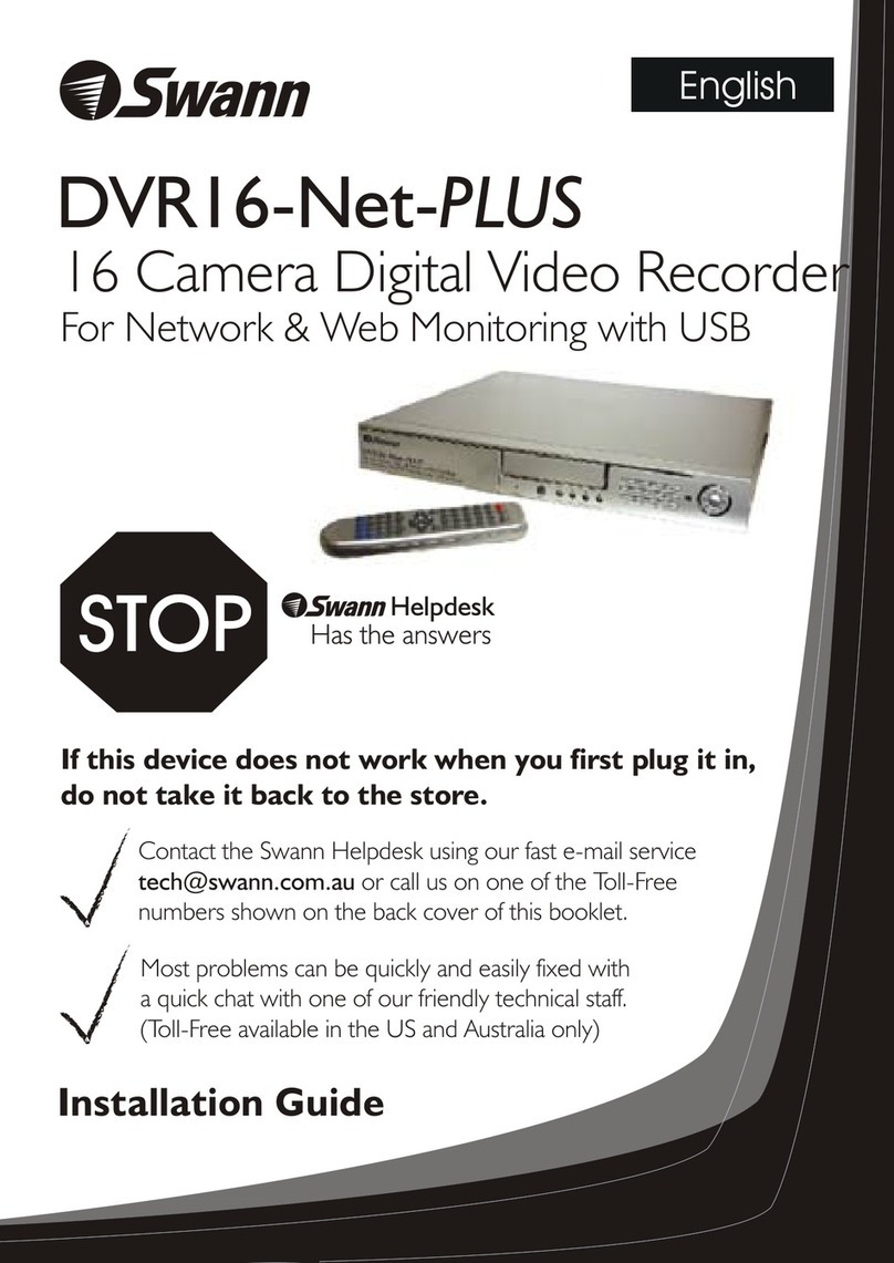
Included in the box is a set of video & power cables for each camera provided. You will see a label on each end, denoting
which end is plugged into which connection. Connect the yellow connection for video and the red connection for power.
Connect the yellow connection on the other end of the cable to each of the video inputs on the DVR. Use the supplied
power splitter to connect to the red connection and then connect the power adapter to the power splitter as illustrated.
Connect the mouse (supplied) to the USB port located at the rear of the DVR. Connect the power adapter (supplied) to the power input on the DVR. There will be a label on the power adapter
indicating that it is for the DVR and not the cameras.
All connections have now been completed. You’re now ready to run through “The Setup Wizard” to configure your DVR.
If you have a Monitor with a VGA connection, connect a VGA cable (not supplied) to the VGA output on the DVR, and
connect the other end to the VGA input on the Monitor. You can skip this step if you are using the supplied HDMI cable.
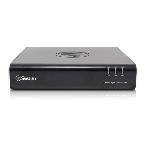
Here are the explanations for the various connections and
lights on the DVR -
1) Video In - Connect the included cameras here.
2) Audio In - For connecting a microphone or some other
audio device.
3) Audio Out - For connecting speakers.
4) HDMI - Connect this to your digital TV with a HDMI input.
5) eSATA - A convenient way to connect an additional hard
drive for expanded storage.
6) VGA - If you have a digital TV or a monitor with VGA
input, connect this to an available input. A VGA cable and
monitor are not required if you are using the HDMI cable
for display.
7) LAN - Connect this to your home network so your DVR
can connect to the Internet.
8) USB - Connect the mouse here. Also able to connect a
Flash Drive to backup recorded events.
9) PTZ - For connecting a RS-485 device such as a PTZ
camera.
10) Power - This is where you connect the power adapter.
11) Power LED - This light will turn on when the DVR has
power.
12) HDD LED - This will flash when the hard drive is
working.
Getting to know your DVR
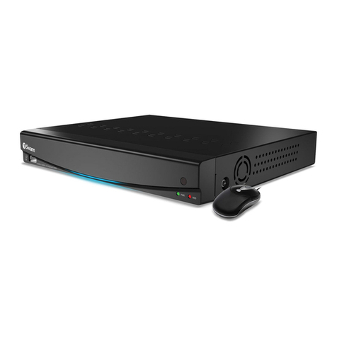
Congratulations on the purchase of your Swann DVR. This quick start guide will assist you on getting your DVR up and
running as soon as possible. We recommend that you connect everything and give it a try before you do a permanent
installation, to make sure nothing was damaged during shipping. On the other side is a detailed connection map which
illustrates the various connections on the DVR.
What does this mean?
Connecting the Cameras
Connect to your Home Network
Connect the Ethernet cable (supplied) to the LAN connection on the DVR, and then connect the other end to a spare
port on the router or wireless access point.
It’s important to do this as it allows the DVR to connect to the Internet to update its internal clock so the time it
shows on the video is always accurate, to send you email notifications and to access from your smartphone or
tablet.
Connect the Mouse
Connect the DVR to your HDTV
Connect the HDMI cable (supplied) to the HDMI input on the DVR, and connect the other end to a spare HDMI input on
the TV. Make sure your HDTV input matches the physical connection used to connect your DVR.
Connect the DVR to your Monitor (optional)
Connect the Power Adapter
2
3
4
6
7
8
1) Video In
2) Audio In
3) Audio Out
4) HDMI
5) eSATA
6) VGA
7) LAN
8) USB
9) PTZ
10) Power
11) Power LED
12) HDD LED
First connect the camera
to the video & power
cable.
Then connect the
provided power splitter
to the other end of the
video & power cable.
ENDVR Quick Start Guide
• Getting to know your DVR
• What does this mean?
• Connecting the Cameras
• Connect to your Home Network
• Connect the Mouse
• Connect the DVR to your HDTV
• Connect the DVR to your Monitor (optional)
• Connect the Power Adapter
Welcome! Lets get started.
QH48_4400071114E | © Swann 2014
The additional USB port can also be used to connect a Flash Drive (not supplied) to backup recorded events.
PTZ
BA DC 12V
IN
LAN&USB
eSATA
75 3 1
86 4 2
VIDEO IN
AUDIO
OUT
AUDIO IN
VGA
HDMI
1 3 4 6 8 9
7
52 10
PWR HDD
8Channel Digital Video Recorder
12
11
Connect the power
adapter to a spare wall
socket.
DC Power
Video Output
Video & Power
Cable
Power Splitter
PTZ
BA DC12V
IN
LAN&USB
eSATA
75 3 1
86 4 2
VIDEOIN
AUDIO
OUT
AUDIOIN
VGA
HDMI
PTZ
BA DC12V
IN
LAN&USB
eSATA
75 3 1
86 4 2
VIDEOIN
AUDIO
OUT
AUDIOIN
VGA
HDMI
USB Intern et Ethernet
432
PTZ
BA DC12V
IN
LAN&USB
eSATA
75 3 1
86 4 2
VIDEOIN
AUDIO
OUT
AUDIOIN
VGA
HDMI
PTZ
BA DC12V
IN
LAN&USB
eSATA
75 3 1
86 4 2
VIDEOIN
AUDIO
OUT
AUDIOIN
VGA
HDMI
HDMIIN 2
HDMIIN 1
PTZ
BA DC12V
IN
LAN&USB
eSATA
75 3 1
86 4 2
VIDEOIN
AUDIO
OUT
AUDIOIN
VGA
HDMI
PTZ
BA DC 12V
IN
LAN&USB
eSATA
75 3 1
86 4 2
VIDEO IN
AUDIO
OUT
AUDIO IN
VGA
HDMI
10 11 12
13 14 15
16 17 18
Connect the Ethernet cable (supplied) to the
LAN connection on the DVR, and then connect
the other end to a spare port on your router or
wireless access point. This allows you to access
the DVR from your smartphone or tablet,
provides Internet access to your DVR to update
its internal clock so the time it shows on the
video is always accurate, and to send you email
notifications.
QH48_4400071114E | © Swann 2014
If your HDTV has a VGA input or you
have a Monitor with a VGA connection,
connect a VGA cable (not supplied) to the
VGA output on the DVR, and connect the
other end to the VGA input on the HDTV
or Monitor.
Connect the power adapter (supplied) to
the power input on the DVR. There will be
a label on the power adapter indicating
that it is for the DVR and not the cameras.
The additional USB port can also be
used to connect a Flash Drive (not
supplied) to backup recorded events.
Connect the HDMI cable (supplied) to the
HDMI input on the DVR, and connect the
other end to a spare HDMI input on the
TV.
Connect the camera to the video and
power cable (supplied). Connect the
yellow connection for video and the red
connection for power.
Connect the provided power splitter to
the video and power cable, then connect
this to the power adapter (supplied).
There will be a label on the power adapter
indicating that it is for the cameras and
not the DVR.
Connect the yellow connection on the
other end of the cable to each of the video
inputs on the DVR.
Connect the mouse (supplied) to
a spare USB port on the DVR.
What are the additional connections for?
Audio In - For connecting a microphone or some other audio device.
Audio Out - For connecting speakers.
eSATA - A convenient way to connect an additional hard drive for
expanded storage.
PTZ - For connecting a RS-485 device such as a PTZ camera.
HDMI IN 2
HDMI IN 1
DC Power
Video Output
Video & Power
Cable
Power Splitter
USB Int ernet Ethernet
432
PTZ
BA DC 12V
IN
LAN&USB
eSATA
75 3 1
86 4 2
VIDEO IN
AUDIO
OUT
AUDIO IN
VGA
HDMI
1 2 3 5
4
1
2
3
4
5
6
6
A VGA cable and monitor are not
required if you are using the HDMI
cable for display.