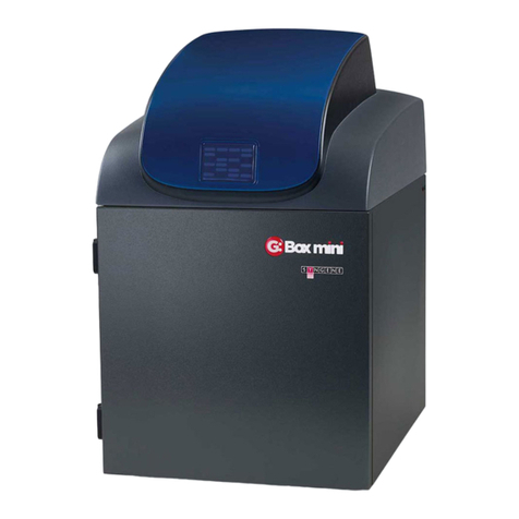
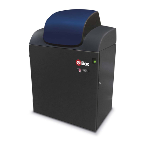
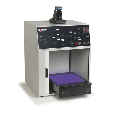
Syngene G:BOX User manual

G:BOX Service Manual
Issue 01
January 2016
SY N GE N E
A D IVISIO N O F T H E SYN O PT ICS GRO U P

NOTICE TO USERS
All possible care has been taken in the preparation of this Service Manual, but Synoptics Limited
accepts no liability for any inaccuracies that may be found.
Synoptics Limited reserves the right to make changes without notice both to this publication and to
the product that it describes.
No part of this publication may be reproduced, stored in a retrieval system or transmitted in any
form or by any means electronic, mechanical, photocopying, recording or otherwise without the
prior permission of the copyright owner.
Published by Syngene, a division of Synoptics Limited.

G:BOX Service Manual Safety - 1
SAFETY INSTRUCTIONS
Safety Practices
This document describes the general safety practices and precautions that must be observed when
operating and maintaining a G:BOX System.
This advice is intended to supplement, not supersede, the normal safety codes in the user’s country.
The information provided does not cover every safety procedure that should be followed. Ultimately,
maintenance of a safe laboratory environment is the responsibility of the user and the user’s
organisation.
Please consult all documentation supplied with the G:BOX System before starting to work with the
instrument. Carefully read the safety information in this document and in the other documentation
supplied. When setting up the instrument or performing analysis or maintenance procedures, strictly
follow the instructions provided.
Warning Notices
Within this User Guide WARNINGS are used to highlight information or instructions that must be
followed in order to avoid personal injury to yourself or other people in the vicinity, e.g. switch off
the mains voltage and remove the mains cord before cleaning.
WARNINGS appear as below:
WARNING
Switch off the mains voltage and remove the mains cord before cleaning.
WARNING
Ensure that all instrument users read and understand the precautions listed below.
WARNING
You are advised to post a copy of the precautions near to or on the instrument
itself.
Precautions
The following precautions must be observed when using a G:BOX System:
Be sure that the voltage of the G:BOX System corresponds to the voltage available where it
is to be installed.
Never remove the side or back panels of the G:BOX System without first shutting down the
instrument and disconnecting the mains cord.

Safety - 2 G:BOX Service Manual
General Operating Conditions
G:BOX Systems have been designed and tested in accordance with the safety requirements of the
International Electrotechnical Commission (IEC). G:BOX Systems conform to IEC61010-1 (Safety
Requirements for electrical equipment for measurement, control and laboratory use) as it applies to
IEC Class 1 (earthed) appliances, and therefore meet the requirements of EC directive 73/23/EEC.
If possible, avoid any adjustment, maintenance or repair to the instrument while it is open and
operative. However, if any adjustment, maintenance or repair is necessary while the instrument is
open, this must be done by a skilled person who is aware of the hazards involved.
Whenever circumstances arise that mean a G:BOX System may be unsafe, make it inoperative. In
particular, a G:BOX System may be unsafe if it:
Shows visible damage.
Fails to perform the intended measurement.
Has been subjected to severe transport stresses.
Has been subjected to prolonged storage in unfavorable conditions.
Environmental Conditions
G:BOX Systems should only be used under the following conditions:
Indoors.
At altitudes below 2000m.
In ambient temperatures between 5°C and 40°C.
With relative humidity below 80% for temperatures up to 31°C, decreasing linearly to 50%
relative humidity at 40°C.
Electrical supply fluctuations not exceeding +10% of the nominal voltage.
WARNING
The protection provided by the equipment may be impaired if the environmental
conditions do not lie within these parameters.

G:BOX Service Manual Safety - 3
Electrical Safety
G:BOX Systems are designed to protect the user from potential electrical hazards. This section
describes some recommended electrical safety practices.
WARNING
Lethal voltages are present at certain points within the instrument.
When the instrument is connected to mains power, removing the instrument
covers is likely to expose live parts.
Even when the power switch is off, high voltages can still be present –capacitors
within the instrument may still be charged even if the instrument has been
disconnected from all live voltage sources.
The G:BOX System must be correctly connected to a suitable electrical supply. The supply must have
a correctly installed protective conductor (earth or ground) and must be installed and checked by a
qualified electrician before connecting the instrument.
WARNING
Any interruption of the protective conductor inside or outside the G:BOX System,
or disconnection of the protective conductor terminal is likely to make the
instrument dangerous.
Intentional interruption of the protective conductor is prohibited.
WARNING
Ensure that the mains supply socket on the instrument is not obstructed, i.e. leave
a gap to allow easy disconnection of the mains cord.
WARNING
If the mains power cord has to be replaced, ensure that the replacement cord is
appropriately rated and approved for the intended use.
When working with the G:BOX System:
Connect the instrument to a correctly installed mains power outlet that has a protective
conductor connection.
Do not operate the instrument with any covers or internal parts removed.
Do not attempt to make internal adjustments or replacements except as directed in the
G:BOX System documentation.
Disconnect the instrument from all live voltage sources before opening it to make any
adjustments, replacements, maintenance or repair. If the opened instrument must be
operated for further adjustment, maintenance or repair, this must only be done by a
supplier’s Service Engineer.

Safety - 4 G:BOX Service Manual
If it is possible that the instrument is no longer electrically safe for use, make the
instrument inoperative and secure it against any unauthorised or unintentional operation.
The electrical safety of the instrument is likely to be impaired if:
It has any signs of visible damage.
If it has been subjected to prolonged storage in unfavourable conditions.
If it has been subjected to severe stress during transportation.
Changing a Fuse
There are two User accessible fuses that may need to be replaced:
These are located in the mains power socket on the rear panel of the G:BOX instrument and
are only accessible when the mains power cord has been removed.
To change the fuses:
WARNING
Switch off the instrument and unplug the mains power cord from the electrical
supply.
Gently pull out the fuse holder.
Replace the fuses with new fuses of the same type and rating. The fuse type is 20 mm x 5
mm IEC127 T 6.3 A H 250V for instruments in all countries.
Replace the fuse holder.
Note: Accessories such as the Transilluminator may have their own fuse.
Note: If the instrument still does not work correctly after replacing the fuses with the correct
replacements, or if the fuses blow repeatedly, contact the supplier’s Office or
Representative.
Electrical Protection
Insulation: Class I rating for external circuits. Only connect equipment that meets the
requirements of IEC 61010-1, IEC 60950 or equivalent standards.
Installation Category: The instruments are able to withstand transient overvoltages typically
present on the mains supply. The normal level of transient overvoltages is impulse
withstand (overvoltage) category II of IEC 60364-4-443.
Pollution Degree 2: Normally only non-conductive pollution occurs. Occasionally, however,
temporary conductivity caused by condensation must be expected.
EMC Compliance
EC Directive
The G:BOX System is designed and tested to meet the requirements of the EC directive 89/336/EEC
and 93/68/EEC. The instrument complies with the EMC standard EN61326 (EMC standard for

G:BOX Service Manual Safety - 5
electrical equipment for measurement, control and laboratory use) and EN55011 (ISM) class A (rf
emissions).
FCC Rules and Regulations
The G:BOX System is classified as a digital device used exclusively as industrial, commercial or
medical test equipment. It is exempt from the technical standards specified in Part 15 of the FCC
Rules and Regulations based on Section 15.103 (c).
UV Safety
The G:BOX System uses UV tubes. If the door is opened the image capture software will
automatically switch off the UV light.
Warning Labels
Warning labels attached to the instrument draw attention to specific hazards - refer to this User
Guide and other documentation provided with the instrument for more details concerning potential
hazards and any precautions or other actions that must be taken.
WARNING
To prevent potential personal injury and damage to the instrument, switch OFF all
components in the system and disconnect them from the mains power supply
before altering, or making any new electrical connections.
Safety Information for Service Personnel
The following section presents safety information with which you need to be familiar before you
service a G:BOX System.
General Safety
Follow these rules to ensure general safety:
Observe good housekeeping in the area of the instrument during and after maintenance.
When lifting any heavy object:
1. Make sure that you can stand safely without slipping.
2. Distribute the weight of the object equally between your feet.
3. Use a slow lifting force. Never move suddenly or twist when you attempt to lift.
4. Lift by standing or by pushing up with your leg muscles; this action removes the
strain from the muscles in your back. Do not attempt to lift any object that weighs
more than 16 kg (35 lb) or that you think is too heavy for you.
Do not perform any action that causes hazards to the customer’s personnel, or that makes
the instrument unsafe.
Before you start the instrument, make sure that other service representatives and the
customer’s personnel are not in a hazardous position.

Safety - 6 G:BOX Service Manual
Place removed covers and other parts in a safe place, away from all personnel, while you
are servicing the instrument.
Keep your toolcase away from walk areas so that other people will not trip over it.
Do not wear loose clothing that can be trapped in the moving parts of an instrument. Make
sure that your sleeves are fastened or rolled up above your elbows. If your hair is long,
fasten it back.
Insert the ends of your necktie or scarf inside clothing or fasten it with a nonconductive clip,
about 8 centimeters (3 inches) from the end.
Do not wear jewelry, chains, metal-framed eyeglasses, or metal fasteners for your clothing.
Metal objects are good electrical conductors.
Wear safety glasses when you are hammering, drilling, soldering, cutting wire, attaching
springs, using solvents, or working in any other conditions that might be hazardous to your
eyes.
After service, reinstall all safety shields, guards, labels, and ground wires. Replace any
safety device that is worn or defective.
Reinstall all covers correctly before returning the instrument to the customer.
Louvers on the instrument help to prevent overheating of internal components. Do not
obstruct fan louvers or cover them with labels or stickers.
Electrical Safety
Follow these rules to ensure electrical safety:
Use only approved tools and test equipment. Some hand tools have handles covered with a
soft material that does not insulate you when working with live electrical currents.
Many customers have, near their equipment, rubber floor mats that contain small
conductive fibers to decrease electrostatic discharges. Do not use this type of mat to
protect yourself from electrical shock.
Find the room emergency power-off (EPO) switch, disconnecting switch, or electrical outlet.
If an electrical accident occurs, you can then operate the switch or unplug the power cord
quickly.
Do not work alone under hazardous conditions or near equipment that has hazardous
voltages.
Disconnect all power before:
-Performing a mechanical inspection.
-Working near power supplies.
-Removing or installing mains units.
Before you start to work on the instrument, unplug the power cord. If you cannot unplug it,
ask the customer to power-off the wall box that supplies power to the instrument, and to
lock the wall box in the off position.

G:BOX Service Manual Safety - 7
If you need to work on an instrument that has exposed electrical circuits, observe the
following precautions:
-Ensure that another person, familiar with the power-off controls, is near you.
-Use only one hand when working with powered-on electrical equipment; keep the other
hand in your pocket or behind your back.
Note: An electric shock can occur only when there is a complete circuit. By observing the above
rules, you may prevent a current from passing through your body.
-When using testers, set the controls correctly and use the approved probe leads and
accessories for that tester.
-Stand on suitable rubber mats (obtained locally, if necessary) to insulate you from
grounds such as metal floor strips and machine frames.
Regularly inspect and maintain your electrical hand tools for safe operational condition.
Do not use worn or broken tools and testers.
Never assume that power has been disconnected from a circuit. Always check that it has
been powered off.
Always look carefully for possible hazards in your work area. Examples of these hazards are
moist floors, nongrounded power extension cables, power surges, and missing safety
grounds.
Do not touch live electrical circuits with the reflective surface of a plastic dental mirror. The
surface is conductive; such touching can cause personal injury and instrument damage.
If an electrical accident occurs:
-Use caution; do not become a victim yourself.
-Switch off power.
-Send another person to get medical aid.
Sensitivity to Electrostatic Discharge
Any instrument part containing transistors or integrated circuits (ICs) should be considered sensitive
to electrostatic discharge (ESD.) ESD damage can occur when there is a difference in charge between
objects. Protect against ESD damage by equalizing the charge so that the instrument, the part, the
work mat, and the person handling the part are all at the same charge.
When handling ESD-sensitive parts:
Keep the parts in protective packages until they are inserted into the product.
Avoid contact with other people.
Wear a grounded wrist strap against your skin to eliminate static on your body.
Prevent the part from touching your clothing. Most clothing is insulative and retains a
charge even when you are wearing a wrist strap.
Use the black side of a grounded work mat to provide a static-free work surface. The mat is
especially useful when handling ESD-sensitive devices.

Safety - 8 G:BOX Service Manual
Select a grounding system, such as those listed below, to provide protection:
-Attach the ESD ground clip to any frame ground, ground braid, or green-wire ground.
-When working on a double-insulated system, use an ESD common ground or reference
point. You can use coax or connector-outside shells on these systems.
-Use the ground prong of the ac plug on ac-operated computers.

G:BOX Service Manual Contents - 1
Table of Contents
OVERVIEW 3
G:BOX Overview........................................................................................................... 3
G:BOX Range................................................................................................................ 4
Minimum System Requirements................................................................................... 6
Operator Controls ........................................................................................................ 6
Rear Panel ......................................................................................................................... 6
Touch Screen PC ............................................................................................................... 6
Connected PC.................................................................................................................... 7
Instrument Set-up - Standard Darkroom ....................................................................... 7
Instrument Set-up - Stretch Darkroom .......................................................................... 8
Operator Mountable Accessories................................................................................ 10
Lights............................................................................................................................... 10
Filters .............................................................................................................................. 12
Switching Instrument On ............................................................................................ 13
G:BOX Typical Accessories .......................................................................................... 14
G:BOX Operator Troubleshooting ............................................................................... 15
G:BOX SERVICE AGENT INSTRUCTIONS 18
G:BOX Service Agent Troubleshooting ........................................................................ 18
G:BOX Service Agent Repair Instructions..................................................................... 24
Side Panel Removal......................................................................................................... 24
Board Replacement ........................................................................................................ 24
LED White Light Unit Replacement................................................................................. 25
UV Light Lamp Replacement........................................................................................... 26
Fuse Replacement........................................................................................................... 27
ON/OFF Rocker Switch Replacement ............................................................................. 27
Mains Inlet Fused Chassis Plug Replacement................................................................. 28
Interlock Switch Replacement ........................................................................................ 28
Electromagnetic Door Catch Replacement..................................................................... 29
Manual Stage UP/DOWN and Stage Override Button Replacement ............................. 30
LED Indicator Replacement............................................................................................. 31
UV Light Override Button Replacement ......................................................................... 31
Tray Interlock Switch Replacement ................................................................................ 32

Contents - 2 G:BOX Service Manual
Stage Magnetic Catch Replacement............................................................................... 32
Camera / Lens Module Replacement ............................................................................. 33
Lens Replacement........................................................................................................... 33
Filter Holder Repair / Replacement................................................................................ 34
G:BOX SPARE PARTS LISTS 36
G:BOX Board Identification......................................................................................... 36
Board Identification Diagrams ........................................................................................ 37
Parts List for a Typical Standard G:BOX ....................................................................... 40
Parts List for a Typical Stretch G:BOX .......................................................................... 45
Gallery of Parts - G:BOX.............................................................................................. 52
OPERATOR MAINTENANCE 69
Looking After a G:BOX Instrument .............................................................................. 69
Cleaning a G:BOX Instrument ......................................................................................... 69
Contacting Syngene .................................................................................................... 69

3 G:BOX Service Manual
OVERVIEW
G:BOX Overview
The G:BOX range are high resolution, multi-application image analysis systems. G:BOX can be used
for a wide range of imaging applications including; chemiluminescence, fluorescent blots and gels,
visible blots and gels, and even 2D gels.
The basic G:BOX Instrument comprises two main components:
Darkroom - this provides a completely black environment into which the sample to be
imaged is enclosed. Samples can be placed into the Darkroom directly onto a screen, a
transilluminator or a white light pad.
The affordable models in the G:BOX range utilise the standard sized Darkroom. The optimum
models utilise the extended Darkroom, which has a fully variable, motor driven stage, which
is controlled by the GeneSys software.
Imaging System - samples are illuminated with a specified light source or sources and imaged
directly or through specified filters. Six types of light source are available:
LED lights of known wavelengths (red, green, blue and IR) located high up on the
sides of the Darkroom. These illuminate the sample from above. These are modular
units, replaceable by the operator.
UV lamps of known wavelengths (254-nm, 302-nm and 365-nm) located above the
LED light modules on either side of the instrument. These illuminate the sample from
above.
Blue LED lights on transilluminators, providing side and through lighting of samples.
UV lights on transilluminators, providing side and through lighting of samples.
LED lights and fibre optics on an edge light unit, for illuminating gels from the edge.
A white light pad , an alternative to using a visible light converter screen over the UV
transilluminator.
In addition, white LED lights are provided on each side of the Darkroom to provide general
illumination when positioning and setting up samples.
Between the Darkroom and the lens/camera there is a rotating screen with spaces for up to
7 filters to be inserted. The screen is indexed, enabling the location and specification of each
installed filter to be specified to the GeneSys software.
G:BOX Instruments have a new generation of camera - having 3.8, 4, 4.2, 6 or 9 million pixels,
giving the system range outstanding sensitivity and versatility.

4 G:BOX Service Manual
G:BOX Range
The G:BOX range comprises five models, as detailed below:
SPECIFICATIONS
G:BOX F3
G:BOX
Chemi XRQ
G:BOX
Chemi XT4
G:BOX
Chemi XX6
G:BOX
Chemi XX9
Image resolution (megapixels)
3.8
4
4.2
6
9
Effective resolution (megapixels)
15.3
16
16.76
18
27
A/D
12/16 bit
16 bit
16 bit
16 bit
16 bit
Greyscales
65 536
65 536
65 536
65 536
65 536
Quantum efficiency @ 425nm
52%
73%
53%
73%
73%
Cooling - regulated
n/a
-57C
-57C
-57C
-57C
Lens (motor driven)
f1.2
f1.2 with
feedback
f0.95 with
autofocus
f0.95 with
autofocus
f0.95 with
autofocus
Filter wheel (7 position)
●
●
●
●
●
UV filter*
●
●
●
●
●
Use with external PC
●
●
●
●
●
Darkroom - standard
●
●
Darkroom - extended with motor driven
stage
●
●
●
EPI LED white lights
●
●
●
●
●
EPI UV 302nm**
●
●
●
●
●
EPI red LED module
●
●
●
●
EPI blue LED module
●
●
●
●
EPI green LED module
●
●
●
●
EPI red LED module M series for
multiplexing
●
●
●
●
EPI blue LED module M series for
multiplexing
●
●
●
●
EPI green LED module M series for
multiplexing
●
●
●
●
EPI IR LED module
●
●
●
●
IR multiplexing kit (680 - 800nm)
●
●
●
●
Visible light converter (33 x 31 cm)
●
●
●
●
●
White light pad for visible stains (20 x 14 or
20 x 30 cm)
●
●
●
●
●
UltraBright LED blue light transilluminator
(20 x 16 cm)
●
●
●
●
●
Edge lighting unit (26.5 x 20 cm)
●
●
●
●
●
UV transilluminator 302nm (20 x 20 cm)***
●
●
●
●
●
Maximum image area (cm)
25.5 x 21
30.5 x 22.7
19 x 19
22.1 x 17.6
22.1 x 17.6
Minimum image area (cm)
4.5 x 3.8
5.5 x 4
9 x 9
10 x 8
10 x 8
W x H x D (cm)
57 x 84 x 45
57 x 84 x 45
57 x 99 x 55
57 x 99 x 55
57 x 99 x 55
Weight (kg)
37
37
45
45
45
Supply voltage (V ac)
115 / 240
115 / 240
115 / 240
115 / 240
115 / 240
* other emission filters are available
** other wavelengths are available
*** other sizes and wavelengths are available including dual wavelength

G:BOX Service Manual 5
The models in the G:BOX range are suited to the applications detailed below:
APPLICATIONS
G:BOX F3
G:BOX Chemi XRQ
G:BOX Chemi XT4
G:BOX Chemi XX6
G:BOX Chemi XX9
Affordable system for
routine fluorescent and
visible gel imaging.
Affordable system for
fluorescent and visible gels
and chemiluminescent
Western blots.
Optimum performance
system. Highly sensitive for
advanced chemiluminescent
Western blots, multiplex
gels and routine imaging of
fluorescent and visible gels
and blots.
Optimum performance
system. Highly sensitive for
advanced chemiluminescent
Western blots, multiplex
gels, IR and routine imaging
of fluorescent and visible
gels and blots. Higher spatial
resolution for advanced
applications including 2D.
Optimum performance
system. Super high
sensitivity for advanced
chemiluminescent Western
blots, multiplex gels, IR and
routine imaging of
fluorescent and visible gels
and blots. Optimum spatial
resolution for advanced
applications including 2D.
High resolution 3.8MP
camera for good spatial
resolution.
High resolution, high QE
(73% @ 425nm), 4MP
camera with enhanced
cooling for longer exposure
times - suitable for
chemiluminescence.
High resolution 4.2MP
camera with high sensitivity.
Advanced cooling for very
long exposure times.
Super high resolution, high
QE (>73% @ 425nm), 6MP
camera, providing
outstanding sensitivity for
chemiluminescence.
Optimum high resolution,
high QE (>73% @ 425nm),
9MP camera, providing
outstanding sensitivity for
chemiluminescence.
Effective resolution up to
15.3MP.
Effective resolution up to
16MP.
Effective resolution up to
16.76MP.
Effective resolution up to
18MP.
Effective resolution up to
27MP.
Motor driven lens with
feedback.
Motor driven lens with
feedback.
Motor driven lens with
feedback.
Motor driven lens with
feedback.
Motor driven lens with
feedback.
Integral white LED lighting
for sample positioning,
visible light applications and
colorimetric markers.
Integral white LED lighting
for sample positioning,
visible light applications and
colorimetric markers.
Integral white LED lighting
for sample positioning,
visible light applications and
colorimetric markers.
Integral white LED lighting
for sample positioning,
visible light applications and
colorimetric markers.
Integral white LED lighting
for sample positioning,
visible light applications and
colorimetric markers.
Motor driven 7-position
filter wheel with UV filter to
extend applications.
Motor driven 7-position
filter wheel with UV filter to
extend applications.
Motor driven 7-position
filter wheel with UV filter to
extend applications.
Motor driven 7-position
filter wheel with UV filter to
extend applications.
Motor driven 7-position
filter wheel with UV filter to
extend applications.
Automatic or manual
control using GenSys.
Automatic or manual
control using GenSys.
Automatic or manual
control using GenSys.
Automatic or manual
control using GenSys.
Automatic or manual
control using GenSys.
Pre-defined 1-click protocols
for rapid imaging.
Pre-defined 1-click protocols
for rapid imaging.
Pre-defined 1-click protocols
for rapid imaging.
Pre-defined 1-click protocols
for rapid imaging.
Pre-defined 1-click protocols
for rapid imaging.
Unlimited user saveable
protocols.
Unlimited user saveable
protocols.
Unlimited user saveable
protocols.
Unlimited user saveable
protocols.
Unlimited user saveable
protocols.
Use with UV
transilluminator for DNA
imaging.
Use with UV
transilluminator for DNA
imaging.
Use with UV
transilluminator for DNA
imaging.
Use with UV
transilluminator for DNA
imaging.
Use with UV
transilluminator for DNA
imaging.
Use converter screen for
visible light applications
such as protein gels.
Use converter screen for
visible light applications
such as protein gels.
Use converter screen for
visible light applications
such as protein gels.
Use converter screen for
visible light applications
such as protein gels.
Use converter screen for
visible light applications
such as protein gels.
Use with blue LED
UltraBright transilluminator
for safe-dye applications.
Use with blue LED
UltraBright transilluminator
for safe-dye applications.
Use with blue LED
UltraBright transilluminator
for safe-dye applications.
Use with blue LED
UltraBright transilluminator
for safe-dye applications.
Use with blue LED
UltraBright transilluminator
for safe-dye applications.
Includes unlimited copies of
GeneTools analysis
software.
Includes unlimited copies of
GeneTools analysis
software.
Includes unlimited copies of
GeneTools analysis
software.
Includes unlimited copies of
GeneTools analysis
software.
Includes unlimited copies of
GeneTools analysis
software.
IQ/OQ qualification
protocols as available.
IQ/OQ qualification
protocols as available.
IQ/OQ qualification
protocols as available.
IQ/OQ qualification
protocols as available.
IQ/OQ qualification
protocols as available.
Built-in light gantries for LED
EPI illumination options.
Built-in light gantries for LED
EPI illumination options.
Built-in light gantries for LED
EPI illumination options.
Built-in light gantries for LED
EPI illumination options.
Use IR multiplex kit, LED EPI
modules and filters to image
IR blots using dyes from
LICOR®and DyLight.
Variable position, motor
driven sample stage takes
large to small gel formats,
controlled by GeneSys
autofocus function.
Variable position, motor
driven sample stage takes
large to small gel formats,
controlled by GeneSys
autofocus function.
Variable position, motor
driven sample stage takes
large to small gel formats,
controlled by GeneSys
autofocus function.
Powerful automatic
multiplex capture protocol
using red, green or blue LED
EPI modules.
Powerful automatic
multiplex capture protocol
using red, green or blue LED
EPI modules.
Powerful automatic
multiplex capture protocol
using red, green or blue LED
EPI modules.
Use IR multiplex kit, LED EPI
modules and filters to image
IR blots using dyes from LI-
COR®and DyLight.
Use IR multiplex kit, LED EPI
modules and filters to image
IR blots using dyes from LI-
COR®and DyLight.
Use IR multiplex kit, LED EPI
modules and filters to image
IR blots using dyes from LI-
COR®and DyLight.
Use edge lighting unit for 2D
gel imaging (DIGE).
Use edge lighting unit for 2D
gel imaging (DIGE).
Use edge lighting unit for 2D
gel imaging (DIGE).

6 G:BOX Service Manual
APPLICATIONS INDEX
G:BOX F3
G:BOX
Chemi XRQ
G:BOX
Chemi XT4
G:BOX
Chemi XX6
G:BOX
Chemi XX9
DNA gels
●
●
●
●
●
Protein gels
●
●
●
●
●
Multiplex gels - 3 or more colours
●
●
●
●
Colony counting
●
●
●
●
●
2D Gels (DIGE)
●
●
●
Chemiluminescence blots
●
●
●
●
Colorimetric blots
●
●
●
●
●
Stain free imaging
●
●
●
●
Films
●
●
●
●
●
IR imaging
●
●
●
●
Bioluminescence
●
●
●
●
GFP plant imaging
●
●
●
●
Minimum System Requirements
The GeneSys software can operate on the following Microsoft Windows Operating Systems:
Windows 7 Professional (32 bit and 64 bit versions) (64 bit versions of Windows only work
with recent camera units - check with Syngene, camera serial number required)
or
Windows 8 Professional - compatability similar to Windows 7 above
Note: Home versions of the Windows Operating Systems are not supported.
Please refer to the Syngene website FAQs Gel documentation and analysis section for the up-to-date
minimum system requirements.
Operator Controls
Rear Panel
The rear panel of the G:BOX Instrument contains two User controls:
An ON/OFF rocker switch, used to power on / power off the instrument.
For instruments fitted with a stretch darkroom only, a Stage Safety Cut-out switch, used to
reset the power supply to the Stage mechanism if it has been automatically isolated due to
the mechanism jamming or drawing too much power.
Touch Screen PC
As an aid to cleanliness and good housekeeping the PC used to run the GeneSys software can utilise a
touch screen. This can be operated quite easily while wearing surgical gloves and can be wiped clean
as required.

G:BOX Service Manual 7
Operations using the touch screen are limited to two basic actions; tapping, and touching and
dragging.
Tapping corresponds to clicking on a 'conventional' computer mouse.
Double tapping corresponds to double-clicking on a 'conventional' computer mouse.
Touching and dragging corresponds to scrolling or dragging using a 'conventional' computer
mouse.
Holding a tap corresponds to making the right click menu appear
Connected PC
The keyboard and mouse of an external PC connected to a G:BOX Instrument function as normal.
Instrument Set-up - Standard Darkroom
Make sure that the Laboratory bench is strong enough to support the G:BOX Instrument and is stable
and level.
Caution
Do not power on any of the components until instructed to.
Make the following cable connections:
1. Connect the mains power cord between a power supply socket and the
Instrument. DO NOT switch on.
WARNING
Ensure that the mains supply socket on the Instrument is not obstructed, i.e. leave
a gap to allow easy disconnection of the mains cord.
2. Connect the Darkroom to Camera power lead between the 9-way D-type socket
on the Darkroom and the jack socket on the Camera unit.
3. Connect the Camera to PC lead to the USB Mini-B connector on the Camera. DO
NOT connect to the PC.
4. Power the Darkroom - ON/OFF switch on the back of the Darkroom.
5. Install the Transilluminator into the runners. Connect the flying mains lead from
the back of the Darkroom to the socket on the back of the Transilluminator.
Power the Transilluminator - ON/OFF switch on the front of the unit. If the unit
has one, set the Transilluminator Power rocker switch on the front of the unit to
100%.
6. Startup the PC and install the GeneSys software.
7. Connect the Camera to PC lead to a USB Type A connector on the PC. The Camera
and PC will automatically start to communicate and the Camera drivers will start
to load onto the PC. If a warning box appears on the PC monitor containing a
message that the drivers are unsigned or unverified, then choose the option to
proceed with the installation.

8 G:BOX Service Manual
8. Connect the Darkroom to PC lead to the 9-way D-type connector on the
Darkroom. Connect the other end of the lead to the 9-way D-type connector on
the serial/USB converter. Then connect the converter to a USB Type A connector
on the PC.
Note: Check the latency setting on the serial/USB converter, as described in G:BOX Service Agent
Troubleshooting on page 18.
Note: If the PC has a serial 9-way D-type male connecter, then the female 9-way D-type connector
on the Darkroom to PC lead may be connected directly to the PC, without attaching the
converter.
Note: The GeneSys software requires the PC to be equipped with an OpenGL compatible graphics
card with a resolution of at least 1280 x 900 with true colour, with DPI set to normal size
(96 DPI).
9. Install the GeneTools software following the prompts given by the Installation
Wizard.
10. Double click the icon to start the GeneSys software.
Instrument Set-up - Stretch Darkroom
Make sure that the Laboratory bench is strong enough to support the G:BOX Instrument and is stable
and level.
Caution
Do not power any of the components until instructed to.
Make the following cable connections:
1. Connect the mains power cord between a power supply socket and the
Instrument. DO NOT switch on.
WARNING
Ensure that the mains supply socket on the Instrument is not obstructed, i.e. leave
a gap to allow easy disconnection of the mains cord.
2. Connect the Darkroom to Stage power cable from the Stage to the Darkroom.
Note that this cable is permanently wired into the Stage.
3. Connect the Darkroom to Camera power lead between the 9-way D-type socket
on the Darkroom and the jack socket on the Camera unit.
4. Connect the Camera to PC lead to the USB Mini-B connector on the Camera. DO
NOT connect to the PC.
5. Power the Darkroom - ON/OFF switch on the back of the Darkroom.
6. Open the Darkroom Door and place a small object against the micro-switch at the
rear left corner of the Sample Tray. Make sure the object holds the micro-switch
in the pushed position. Raise the Stage by simultaneously pressing the Manual

G:BOX Service Manual 9
Stage Up button and the Stage Override button just below the Door Magnet.
Raise the Stage until it is above the lip of the Door, then release both buttons.
7. Remove the object from the micro-switch.
8. Install the Transilluminator into the Stage runners. Connect the flying mains lead
from the Stage to the socket on the back of the Transilluminator. Push the
Transilluminator fully into the Stage runners, listening for the click as it engages
the micro-switch. Power the Transilluminator - ON/OFF switch on the front of the
unit. If the unit has one, set the Transilluminator Power rocker switch on the front
of the unit to 100%.
9. Startup the PC and install the GeneSys software.
10. Connect the Camera to PC lead to a USB Type A connector on the PC. The Camera
and PC will automatically start to communicate and the Camera drivers will start
to load onto the PC. If a warning box appears on the PC monitor containing a
message that the drivers are unsigned or unverified, then choose the option to
proceed with the installation.
11. Connect the Darkroom to PC lead to the 9-way D-type connector on the
Darkroom. Connect the other end of the lead to the 9-way D-type connector on
the serial/USB converter. Then connect the converter to a USB Type A connector
on the PC.
Note: Check the latency setting on the serial/USB converter, as described in G:BOX Service Agent
Troubleshooting on page 18.
Note: If the PC has a serial 9-way D-type male connecter, then the female 9-way D-type connector
on the Darkroom to PC lead may be connected directly to the PC, without attaching the
converter.
Note: The GeneSys software requires the PC to be equipped with an OpenGL compatible graphics
card with a resolution of at least 1280 x 900 with true colour, with DPI set to normal size
(96 DPI).
12. Install the GeneTools software following the prompts given by the Installation
Wizard.
13. Double click the icon to start the GeneSys software.

10 G:BOX Service Manual
Operator Mountable Accessories
Lights
The G:BOX Instrument is provided with the following fixed standard overhead light sources:
Two LED White Light units, each consisting of a strip of eight white LEDs, located on each
side of the Darkroom/Stage;
Two User Replaceable Light Module Gantries, each capable of holding four specific colour
output User Replacable Light Modules, located on each side of the Darkroom/Stage,
immediately below the LED White Light units.
OVERHEAD LIGHT SOURCES
If Replaceable Light Modules have been pre-ordered then these will normally be loose-shipped, in a
padded box in the accessories carton. These are installed as follows:
Desktop PC
Printer
Camera unit
Lens unit
Serial to USB
converter
G:BOX Instrument
(rear) - Hood removed for clarity
G:BOX INSTRUMENT - POWER AND
DATA CONNECTIONS
O
I
DARKROOM/PCNOT USED
CAMERA
LENS
Stage cover
Darkroom
UV LIGHT UNIT
LED WHITE LIGHT UNIT
LED LIGHT GANTRY
This manual suits for next models
5
Table of contents
Other Syngene Laboratory Equipment manuals
Popular Laboratory Equipment manuals by other brands

Hanna Instruments
Hanna Instruments HI931 user manual

natus
natus OLYMPIC STERILE-DRIER 43 instruction manual

Fluke
Fluke PTi120 user manual

CertoClav
CertoClav Vacuum Pro 12L Operational instructions

Agilent Technologies
Agilent Technologies Graphite Tube Atomizer GTA 120 user guide

Biolin Scientific
Biolin Scientific Theta installation manual