Takegawa 02-01-0205 User manual

COPY
/6
02-0-0205,02732020.9.29
☆ Please read carefully before use ☆
Special Clutch Cover Kit (Hydraulic type) Instruction manual
◎ The use ignoring the instructions that are written in the manual, if the accident or damage has occurred, we can not assume any
responsibility for compensation.
◎ This product installation and use, when a problem occurs to after market goods, guarantee other than this product, also can not
assume any in any such matters.
◎ If it was the case or mounting that has been processed like a product, it will not be covered under warranty.
◎ It is not possible to inquire of the combination of other manufacturers.
◎ This product is the above-mentioned vehicle exclusive goods.Is not possible attached to the other vehicle. Please note.
◎ Please refer to the genuine service manual for the above-mentioned compatible models for the assembly work.
◎ Special tools are required to install this product. Please prepare separately.
Lock nut wrench:0796-639000(Genuine Honda tool) or Lock nut wrench:00-0-052(Takekawa tool)
Gear holder:07724-00000(Genuine Honda tool) or Universal holder:00-0-002(Takekawa tool)
◎ When using the sidemirror, an M8 size mount type is required.
~ feature ~
Adaptation model Monkey 25 (JB02-00000 ~ )
Thank you very much for purchasing our products.
Thank you so you will comply with the following matters at the time of use.Before installation, please check your always kit contents.
If there is a point of notice event, Please contact us the dealer of purchase.
◎ If the description, such as photos or Illustration different with this part.
・The hydraulic clutch system improves response and clutch operation.
・R. Crank case cover is made of black painted aluminum die cast, clutch cover is made of billet aluminum and anodized.
・By adopting a paper cartridge oil element, the centrifugal oil lter can be removed and reducing the load on the crankshaft and
improving engine response.
・Thermostat unit (02-0-5052: optional) can be installed. Thermostat prevents overcooling whith oil cooler.
・The oil level window makes it easy to check the oil level.
・Filtered oil ows through the oil element by two passage (crankshaft / transmission) with this kit.
(In the stock clutch cover, only one crankshaft passage passes through the centrifugal lter from oil pump).
※ By connecting our bore-up cylinder (oil outlet equipped model) and oil line hose kit (00-07-0095: optional), the oil through the oil
element can ow to the cylinder head.
・Clutch cover for stock clutch or Takegawa slipper clutch.
In addition, it is possible to upgrade to a clutch cover that supports heavey dutey clutches (wet or dry) by installing optional items.
■ On the street, keep the legal speed and obey the trafc law.
(If you drive faster than the legal speed, you will be punished for violating the Road Trafc Act and overspeeding.)
■ When performing the work, etc., be sure during the cold (when the engine and the mufer is cold). (It may cause burns.)
■ When performing the work, it should be made to prepare the tools for the job. (Breakage of parts, it may cause injury.)
■ Do the work must always specied torque using a torque wrench. (Damage of bolts and nuts, and cause of dropout.)
■ The product and the frame, might have edges or protrusions. Please go to protect your hands when you work. (It may cause injury.)
■ Be sure to each part inspection before operation, check the loosening of the threaded portion, be sure to securely tighten the
specied torque if there is loose. (It may cause detachment of the parts.)
■ The technology and those who no knowledge, please do not to work.(The cause of parts damage etc., could result in falls and accidents.)
■ If you start the engine, be sure in a well-ventilated place. In the sealed such place, please do not start the engine.
(There is a risk of carbon monoxide poisoning.)
■ During operation, when an abnormality occurs, immediately stop the vehicle in a safe place, please stop running. (It may lead to an accident.)
■ When performing the work, do the work safely stabilize the vehicle in a horizontal location.
(There is a risk of injury vehicle collapsed while working.)
■ Inspection, maintenance, the instruction manual or, inspection methods such as service manuals, to protect the way, should be done
correctly.(unsuitable inspection and maintenance, there is a risk that result to an accident.)
■ When carrying out the inspection and maintenance, etc., if found damaged parts, replace the damaged parts to avoid possible to reuse
the parts.(There is a risk that lead to accidents Continued use.)
■ The engine and exhaust system are hot while the engine is running or for a while even the engine is stopped.Never place dangerous or
ammable materials such as gasoline near working area. (May caused re.)
CONTACT Address : 3-5-6 Nishikiorihigashi Tondabayashi Osaka JAPAN
TEL: +8-72-25-357 FAX:+8-72-24-5059 e-mail:[email protected] URL http://www.takegawa.co.jp
Please contact with your name and country name provided. (Only English please)
Caution When the handling of ignoring this display, property damage and human shows the assumption of what injury.
Warning When the handling of ignoring this display people died, shows the contents of the serious injury possibility is
assumed.
◎ Please note. Performance up, the design change, the product and the price in the cost up, etc. are subject to change without notice.
◎ Please be informed that we shall be held harmless against any claim against us whatsoever arising out of use of the products in
racing and the like.
◎ Keep this manual stored until this product is discarded.
Product number 02-0-0205 (Black paint)
02-0-0273 (Silver paint)

COPY
2/6
02-0-0205,02732020.9.29
Product content
4
3
2
5
6
7
24
23
25
26
27
77
8
88
9
0
0
2
3
4
5
6
7
8
9
20
2
22
33
35
28
29
30
3
34
36
37
38
39
39
40 40
42
46
45
44
43
32
8
8
8
42
42
42
49
48
47
48
50
4
5
5
5
5
5
5
5
5
5
52
53
57
55
56
54
Spare

COPY
3/6
02-0-0205,02732020.9.29
Number Product content Quantity Item Number
R.crankcase cover ASSY. 00-02-6208 (Black)
00-02-0466 (Silver)
2 Oil pot window set 00-02-003
3 Thermostat hole cap 00-07-0063 (with O-ring)
4 O-ring, 5mm 00-00-085 (5 pcs)
5 Hole cap 09-06-03 (with O-ring)
6 O-ring, 30mm 00-0-0034 (4 pcs)
7 Oil plug bolt 3 00-07-0072 (with Sealing washer)
8 Sealing washer, 0mm 6 00-07-006 (0 pcs)
9 Flange bolt, 6x2 00-00-0322 (6 pcs)
0 Sealing washer, 6mm 2 00-00-2780
Oil ller cap 00-02-0468 (with O-ring)
2 O-ring, 3mm 00-00-0644 (5 pcs)
3 Clutch cover 00-00-087
4 Release spring 00-00-096
5 O-ring, 30mm(SBR) 00-00-0673
6 O-ring, 30mm(NBR) 00-00-0674 (4 pcs)
7 Release piston 00-02-07 (with O-ring)
8 Brake hose (960mm) 00-06-064
9 Adaptor, 0mm 00-07-0032 (with Sealing washer)(2 pcs)
20 Banjo bolt M0x.25 (Gold 00-07-03 (with Sealing washer)
2 Banjo (Straight) 00-07-0006
22 Bleeder cap 00-02-622
23 Bleeder screw 00-02-623
24 Oil lter spring 00-07-0065
25 Oil lter element 00-02-0027
26 O-ring, 40mm 00-02-0040
27 Oil lter cover 00-02-0470(with O-ring/Bolt)
28 Boll bearing, 600Z 00-0-0
29 C type ring, 28mm 00-00-0643 (3 pcs)
30 O-ring, 2mm 00-00-036
3 Oil through nut 00-00-230
32 Conical spring washer, 4mm 00-02-0036
33 Spacer 00-00-44
34 Clutch release rod, 0mm 00-00-684
35 Clutch release rod, 2mm 00-00-685
36 Orice 00-00-072
37 R.crankcase cover gasket 00-02-0356
38 O-ring, 20mm 00-02-088
39 Dowel pin, 8x2 2 00-00-053 (2 pcs)
40 Flange bolt, 6x6 2 00-00-0879 (5 pcs)
4 Flange bolt, 6x35 00-00-0885 (5 pcs)
42 Hexagon socket head cap screw(low head), 6x6 4 00-00-0377 (4 pcs)
43 Hexagon socket head cap screw(extremely low head), 6x8 00-00-0697 (4 pcs)
44 φ 4 male connector 3
00-00-0570 (each 5 pcs)
45 φ 4 female connector 3
46 Male connector cover 2
47 Female connector cover 2
48 Zip-tie, 200mm 2 00-00-079 (0 pcs)
49 Brake uid, DOT4 (200cc) 06-08-009
50 Clutch master cylinder ASSY. 02-02-203
5 Flange bolt, 6x40 9 00-00-0886 (5 pcs)
52 Hexagon bolt, 8x45 00-00-094
53 U nut, M2x.25 00-00-095
54 Coller 00-00-2594
55 Coller 2 00-00-2595
56 Plain washer, 8mm 00-00-0076 (0 pcs)
57 Shim ring, 2x8x0.5 00-00-0370
Product content
※ Please order in the repair parts are always repair part number.
If it is not the part number order, you may not be able to order.Please be forewarned.
It should be noted, In the case of parts that can not be separately shipment, please order a set part number.

COPY
4/6
02-0-0205,02732020.9.29
Installing the clutch cover
・Attach the lifter rod in the kit to the
ball bearing on the clutch lifter plate.
※ Use 0mm lifter rod for stock clutch,
2mm lifter rod for Takegawa slipper
clutch.
・Attach the O-ring(2mm) to the oil through
nut and apply a engine oil to the O-ring
(2mm).
O-ring
Oil through nutSpacer Conical spring washer
(Note the direction)
・Clean the gasket surface of the R.crankcase,
attach the
dowel pin, and install a new
R.crankcase cover gasket.
・Attach the orice in the kit to the back of
the R.crankcase cover.
6x35
Release spring
Release piston
O-ring (NBR) O-ring (SBR)
O-ring
・Park the motorcycle in a horizontal place
with a maintenance stand, etc.
・Drain engine oil.
・Remove the R.step holder.
・Disconnect clutch cable.
・Loosen the bolts of the R.crankcase cover
several times diagonally and remove the
R.crankcase cover and clamp.
・Remove R.crankcase cover gasket, dowel
pin and orice.
・Remove the bolt, centrifugal oil lter
cover and gasket.
Centrifugal oil lter cover
・Hold the primary drive gear and driven
gear or the centrifugal oil lter rotor,
and remove the centrifugal lter rotor
lock nut using a special tool.
Special tool
:Genuine Honda tool
Lock nut wrench 0796-639000
Gear holder 07724-00000
:Takekawa tool
Lock nut wrench 00-0-052
Universal holder 00-0-002
・Remove washers and centrifugal lter rotor.
■ Mounting procedure ※ Please refer to the Genuine Service Manual for detailed mounting methods and specied torques that are not
specically described.
Note:Be sure that you protect specied torque.
Oil through nut
Torque:64N・m(6.6kgf・m)
Note:Be sure that you protect specied torque.
Flange bolt 6x35,6x40
Torque:9.8N・m(.0kgf・m)
Pivot nut
Mounting bolt
R.step holder
Dowel pin
Gasket
Bolt
Lock nut wrench Gear holder
Orice
・Attach the spacer, conical spring washer
(4mm),and oil through nut to the
crankshaft in this order, hold the spacer
with a spanner,and tighten the oil through
nut to the specied torque.
・Attach R.Crankcase cover and clamp with
ange bolt and ange bolts,divide bolts
several times diagonally and tighten to
specied torque.
(Use the kit ange bolts (6x35) at the locations
shown by the arrows in the gure below)
・Attach the O-ring(20mm) to the clutch
cover and apply a engine oil to the
O-ring(20mm).
・Assemble the O-ring 30mm (SBR / NBR) to the
release piston then attach the release spring.
※ Apply a thin layer of rubber grease to
the O-ring then assemble.
※ Each O-ring has a specied mounting position.
As shown in the photo, install the O-ring
(SBR) on the spring side and the O-ring
(NBR) on the clutch side.
・Attach the assembled release piston to
the clutch cover.
※ Apply a thin coat of rubber grease to
the cylinder side of the clutch cover and
assemble it.
※ Caution:forcibly assemble the release
piston into the cylinder, the O-ring will
be damaged.

COPY
5/6
02-0-0205,02732020.9.29
Installing the oil lter cover
O-ring
・Insert 6x8 hexagon socket head bolt
(extremely low head)with 6mm sealing
washer, attach to clutch cover, and
tighten with specied torque.
・With the“UP”mark on the bracket facing
upward, attach the master cylinder assembly,
and tighten the ange bolts(in the order of
upper and lower) with the specied torque.
■ Mounting procedure ※ Please refer to the Genuine Service Manual for detailed mounting methods and specied torques that are not
specically described.
Note:Be sure that you protect specied torque.
Hexagon socket head cap screw(low head),6x6
Torque:9.8N・m(.0kgf・m)
Note:Be sure that you protect specied torque.
Hexagon socket head cap screw
(extremely low head),6x8
Torque:6.3N・m(0.64kgf・m)
Note:Be sure that you protect specied torque.
Flange bolt
Torque:.8N・m(.2kgf・m)
Note:Be sure that you protect specied torque.
Flange bolt,6x6
Torque:9.8N・m(.0kgf・m)
・Place the oil lter spring in the R.crankcase
cover (t it into the guide of the case),
put the oil lter element, attach the
O-ring(40mm) to the oil lter cover, apply
engine oil,and attach the ange bolt(6x6),
Tighten with specied torque.
※ Make sure the oil lter element attached
the guide on the oil lter cover.
※ Caution:If the oil lter spring does not
t inside of the guide(of the oil lter
element), there will be a gap between the
oil lter cover and the R.crankcase cover.
This may cause the oil leaks.
・Attach the clutch cover to the R.crankcase
cover, install it with the Hexagon socket
head cap screw(low head)(6x6) and
tighten it to the specied torque.
・Attach the bleeder screw (with rubber
cap) temporarily, then attach the adaptor
with aluminum sealing washer(0mm) to the
clutch cover with the specied torque.
・Remove the connector and switch cover
from the clutch lever, and remove the
lever from the handle bar.
Bleeder screw Adaptor 0mm
Note:Be sure that you protect specied torque.
Adaptor 0mm
Torque:2.7N・m(.3kgf・m)
・Attach the brake hose (960 mm) with hold the
adaptor(by wrench as shown), and tighten
the hose tting to the specied torque.
Route the brake hose(960 mm) to the clutch
master cylinder,sealing washer(0 mm),banjo
(straight),sealing washer(0mm)in order,
install with banjo bolt(M0x.25,gold),and
hose. Tightening with the specied torque.
Note:Be sure that you protect specied torque.
Banjo bolt
Torque:4.7N・m(.5kgf・m)
Hose tting
Torque:5.9N・m(0.6kgf・m)
・Cut the wiring of the connector (removed
from the stock clutch lever) and the
wiring of the clutch master cylinder ASSY.
with electrical connector.
Master
cylinder
L.Handlebar
switch wire
Green White
Green Red
Green Yellow
Black
Note:Caution:O-ring is installed incorrectly,
the engine may be damaged.
Vinyl hose
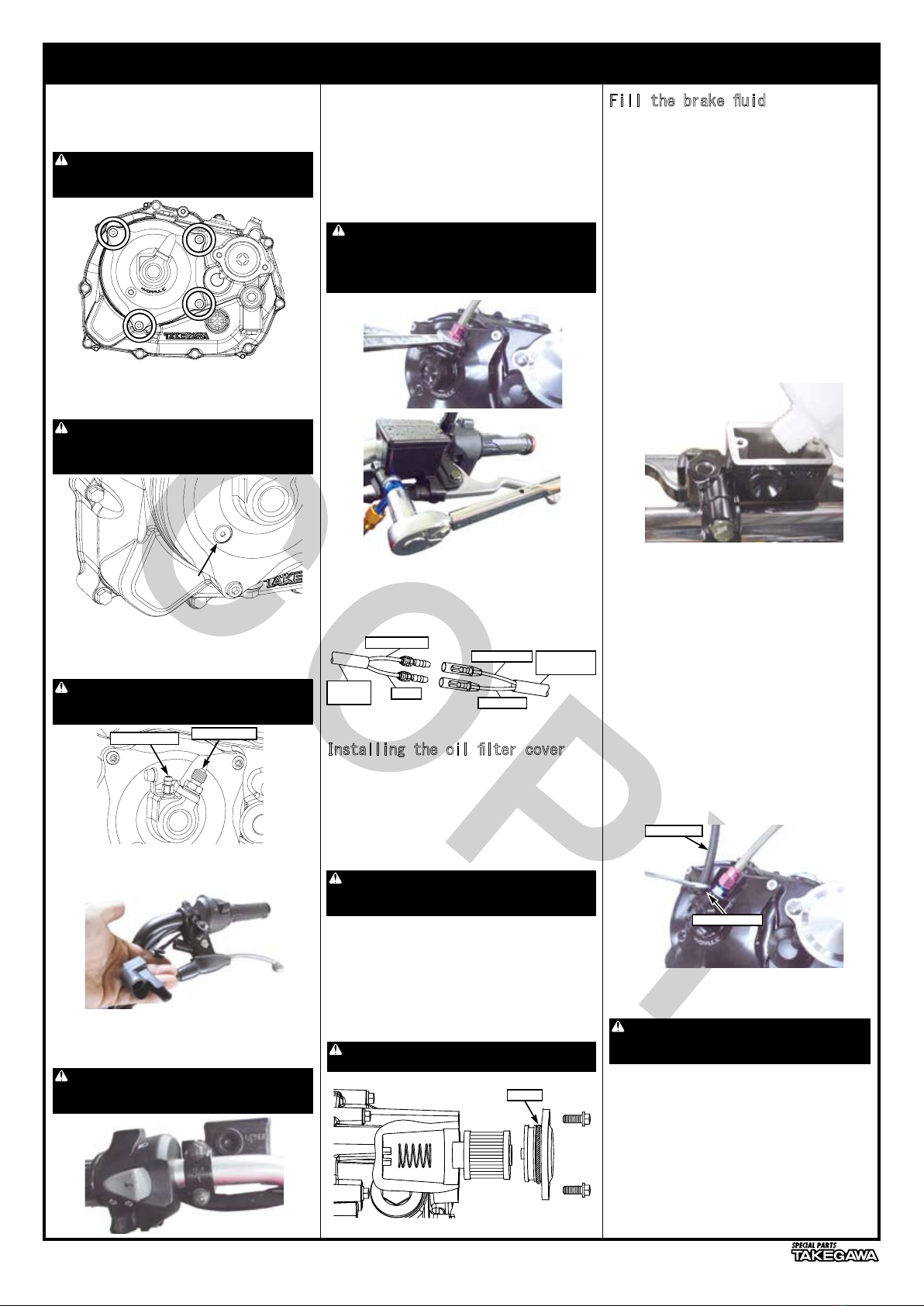
・Remove the reservoir cap and check that
the bleeder screw and banjo bolt are well
tightened. Check and ll the brake uid
to the upper limit line of the reservoir
and operate the clutch lever to ll the
brake uid in the clutch system.
Repeat this until no air bubbles come out
from the primary port in the reservoir
(until the clutch lever feels some weight).
※ To prevent chemical reaction, do not mix
different brands of uid.
※ Caution:brake uid will damage the
painted surface, so do not let it adhere
to the parts.
If attached, wash with water.
Fill the brake uid
・Attach a vinyl hose to the bleeder screw
and receive it with an appropriate cup on
the other side of the tube. Grip the
bleeder screw about /2 turn until the
tip of the clutch lever hits the grip,
tighten it again, slowly release the
clutch lever, and leave it for a few
seconds as it is completely returned.
※ Do not release the lever with the
bleeder screw loosened.
・Repeat this until no bubbles come out
from the bleeder.
※ Caution: attention to the brake uid
level in the master cylinder, ll it
before lower limit line.
Bleeder screw
・Tighten the bleeder screw to the specied
torque.
・When air bleeding is completed, ll the
brake uid to the upper limit line of the
reservoir and attach the diaphragm and
cap.
・Secure the brake hose with a zip-tie
(200 mm) to avoid interfere with other
parts.
Note:Be sure that you protect specied torque.
Bleeder screw
Torque:7.8N・m(0.8kgf・m)

COPY
6/6
02-0-0205,02732020.9.29
・Attach R.step holder with shim ring
(2x8x0.5),U nut(M2x.25),washer (8mm)
and hex bolt (8x45).
After assembly
・After conrming that the drain bolt
{T=24N・m(2.4kgf・m)}is tightened, pour
engine oil, attach the O-ring to the hole
cap, apply a small amount of engine oil to
the O-ring, Tighten to the specied torque.
● When installing an oil hose to the
oil outlet of the cylinder
Note:
Never attach the thermostat unit or
oil hole plug when the oil hose is
not connected to the clutch cover.
Oil passage will closed and engine
may be damaged.
When not installing an oil cooler
・Never install a thermostat unit or oil
hole plug.
Remove a thermostat unit or oil hole
plug.
Note:When the thermostat unit or oil hole
plug is installed, the oil passage is
closed and the engine may be damaged.
・Set color and color 2 on the back side
of the R.step holder.
Coller 2
Coller
Caution:installing the oil line
hose kit (00-07-0095)
・Bend the clamp to avoid lower sensor wire
clamp interferes with the oil line.
Plain washer 8mm
Hex bolt 8x45
■ Mounting procedure ※ Please refer to the Genuine Service Manual for detailed mounting methods and specied torques that are not
specically described.
Note:Be sure that you protect specied torque.
Hole cap
Torque:.8N・m(.2kgf・m)
Note:Be sure that you protect specied torque.
Hole cap
Torque:2.7N・m(.3kgf・m)
Note:Be sure that you protect specied torque.
U nut M2x.25
Torque:54N・m(5.5kgf・m)
Hex bolt 8x45
Torque:3N・m(3.kgf・m)
upper limit
lower limit
Caution
Precautions when installing an
oil cooler
● When installing an optional
thermostat unit
・Installing the thermostat unit.
・Remove the two oil plug bolts, attach an
adapter that matches the type of hose to
be used, and connect the hose.
※ Check the thermostat unit instruction
manual.
※ Check the oil cooler kit instruction
manual and adapter instruction manual.
● When not installing the thermostat
unit
・Remove the thermostat hole cap and insert
the oil hole plug (00-02-039) into the
oil hole.
・Apply engine oil to the O-ring of the
thermostat hole and tighten the hole cap
to the specied torque.
・Do not use oil hole plugs (00-02-0).
Thermostat
hole cap
Oil hole plug
Note:If use the oil hole plug (00-02-0),
the oil passage will be closed and the
engine may be damaged.
∴ Recommended oil
SAE 0W-40 20W-50
API classication
: SG, SH, SJ, SL equivalent
JASO standard : MA
∴ Oil capacity
When changing oil : 900cc
When overhauled :00cc
・For the engine oil viscosity, refer to the
gure and use the oil with the viscosity
suitable for the environment and the
outside temperature.
※ Check the amount of oil in the oil level
check window frequently, and if it is
below the lower limit, add the oil.
Shim ring 2x8x0.5
U nut M2x.25

COPY
/2
02-02-203,06-08-692020.7.4
Master Cylinder Instruction manual
◎ The use ignoring the instructions that are written in the manual, if the accident or damage has occurred, we can not assume any responsibility for
compensation.
◎ This product installation and use, when a problem occurs to after market goods, guarantee other than this product, also can not assume any in any
such matters.
◎ If it was the case or mounting that has been processed like a product, it will not be covered under warranty.
◎ It is not possible to inquire of the combination of other manufacturers.
◎ It’s doesn’t have an oil level check window. Please check the amount of brake uid on the upper limit line of the oil cup.
◎ In addition, this manual are intended for those who have a basic skills and knowledge.
If no experience of mounting, etc., who preparation of such a tool is insufcient, we recommend that it is your request to the shop with a
technical credit.
■ When performing the work, etc., be sure during the cold (when the engine and the mufer is cold). (It may cause burns.)
■ When performing the work, it should be made to prepare the tools for the job. (Breakage of parts, it may cause injury.)
■ When using a blade etc, protect your hands and handle with care.(It may cause injury.)
■ Do the work must always specied torque using a torque wrench. (Damage of bolts and nuts, and cause of dropout.)
■ The product and the frame, might have edges or protrusions. Please go to protect your hands when you work. (It may cause injury.)
■ Be sure to each part inspection before operation, check the loosening of the threaded portion, be sure to securely tighten the specied torque
if there is loose. (It may cause detachment of the parts.)
■ Be careful that the brake uid does not contact your skin. After work, wash your hands thoroughly with water. Otherwise, you will have a rough skin.
■ Please handle the brake uid with great care, because the brake uid, if spilled on painted surfaces, resin parts, or rubber products, will deteriorate or
damage these parts. If the uid is spilled on these parts, wash them immediately with water. Otherwise, the spilled portions will deteriorate or get damaged.
■ Please use only the specied brake uid. Don not use the different brands of brake uids together. Otherwise, the mixed use of the brake uids
will cause technical troubles or chemical reaction.
■ During operation, when an abnormality occurs, immediately stop the vehicle in a safe place, please stop running. (It may lead to an accident.)
■ Plastic bags of product packaging, you can either be stored in a place that is out of reach of children, it should be discarded.
(When the children or wearing, there is a risk of suffocation.)
■ When performing the work, do the work safely stabilize the vehicle in a horizontal location.(There is a risk of injury vehicle collapsed while working.)
■ Get the brakes installed by a skilled mechanic at facilities with special instruments and tools.(Otherwise, the wrong installation will cause accidents.)
■ Inspection, maintenance, the instruction manual or, inspection methods such as service manuals, to protect the way, should be done correctly.
(unsuitable inspection and maintenance, there is a risk that result to an accident.)
■ When carrying out the inspection and maintenance, etc., if found damaged parts, replace the damaged parts to avoid possible to reuse the parts.
(There is a risk that lead to accidents Continued use.)
◎ With the foreseeable incidents in mind, we have listed up these precautions for your correct use of the products and for the prevention of dangers
or damages to you and other people. We do request you to take these important safety precautions against dangers.
②
①
Number Product content Quantity Item Number
Master cylinder ASSY.
2 Turn signal sub-wiring(HONDA Type-) 37600-KCZ-T00
A B 記号 Product content Quantity Item Number
A Brake lever(Black) 06-08-60L
B Brake lever(Silver) 02-0-027
C Handle bracket 06-08-62
D Brake switch 00-06-02
Item parts
DC
※ Photo: front brake master cylinder.
Handle pipe diameter Type Piston diameter Mirror screw diameter Product number
22.2mm Clutch master cylinder 2.7mm M8(Clockwise screw) 02-02-203
Front brake master cylinder mm 06-08-69
CONTACT Address : 3-5-6 Nishikiorihigashi Tondabayashi Osaka JAPAN
TEL: +8-72-25-357 FAX:+8-72-24-5059 e-mail:[email protected] URL http://www.takegawa.co.jp
Please contact with your name and country name provided. (Only English please)
☆ Please read carefully before use ☆
Thank you very much for purchasing our products.Thank you so you will comply with the following matters at the time of use.
Before installation, please check your always kit contents.If there is a point of notice event, Please contact us the dealer of purchase.
◎ If the description, such as photos or Illustration different with this part.
Caution When the handling of ignoring this display, property damage and human shows the assumption of what injury.
Warning When the handling of ignoring this display people died, shows the contents of the serious injury possibility is
assumed.
◎ Please note. Performance up, the design change, the product and the price in the cost up, etc. are subject to change without notice.
◎ Please be informed that we shall be held harmless against any claim against us whatsoever arising out of use of the products in racing and the like.
◎ Keep this manual stored until this product is discarded.
Product content
※ Please order in the repair parts are always repair part number.
If it is not the part number order, you may not be able to order.
Please be forewarned.
It should be noted, In the case of parts that can not be separately shipment,
please order a set part number.

COPY
2/2
02-02-203,06-08-692020.7.4
■ Optional Parts
Fitting color:Red
Hose:Clear
Hose length(mm) Product number
600 00-06-007
675 00-06-06
Banjo bolt(M0 x P.25)(Red) 00-07-022 (Sealing washer 2 pcs)
Banjo bolt(M0 x P.0) (Red) 00-07-0079 (Sealing washer 2 pcs)
Banjo bolt(M0 x P.25)(Gold)00-07-03 (Sealing washer 2 pcs)
Banjo(25°)(Blue) 00-07-0037
Banjo(45°)(Blue) 00-07-0039
Banjo(straight)(Blue) 00-07-0006
Adaptor(Blue) 00-07-0032 (2 pcs / Sealing washer 2 pcs)
Sealing washer 00-07-006(0 pcs)
■ Banjo and banjo bolt will be sold one pieces each.
When useing the master cylinder and caliper with our “slim line hose”, banjo bolts x2, banjo x2 and sealing washers x4 are required.
■ This master cylinder is compatible with M0xP.25 banjo and adapter.
For the brake caliper side, please check the screw size and the pitch to select the banjo and adapter.
■ There are 3 types of banjo, straight,25°, 45° available.
“Slim line hose” length and banjo can be selected depends on the position of the handlebar and it’s specications.
Banjo bolt
(M0 x P.25)(M0 x P.0)
Sealing washer
Hose length(mm)
Banjo(Straight)
Fitting
Mount the master cylinder assembly with the UP mark on the handle bracket facing up.
Tighten the ange bolts (upper/lower) with the specied torque.
Refer to the installation manual of the brake/clutch kit, attach the hose, and bleed the air.
Adaptor(M0 x .25)
Banjo(25°) Banjo(45°)
Fitting color:Gold
Hose:Smoke
Hose length(mm) Product number
420 06-08-0092
500 00-06-058
775 00-06-062
960 06-08-005
■ About the use of master cylinder ■
Shaded area
When you dismount the lever from the master cylinder, the looseness of the piston
and the lever might be changed.
In that case, rasp the shaded area of the lever and adjust.
■ It is a fold-able type lever that does not
easily break when it crash.
■ The lever position can be adjusted by 6 step .
■ By replacement, the lever length will be about
30 mm longer, so lever operation will be lighter.
Brake uid
DOT4(200cc)
06-08-009
Aluminum billet (foldable) L.lever
Clutch lever:02-0-070
Brake lever:06-08-0206
Note: Be sure that you protect specied torque.
Flange bolt
Torque:.8N・m(.2kgf・m)
■ Mounting procedure ※ Please refer to the Genuine Service Manual for detailed mounting methods and specied torques that are not
specically described.
Straight
This manual suits for next models
3
Table of contents
Other Takegawa Motorcycle Accessories manuals

Takegawa
Takegawa PC20 User manual

Takegawa
Takegawa 03-05-0020 User manual

Takegawa
Takegawa 02-01-0284 User manual

Takegawa
Takegawa 09-03-0708 User manual

Takegawa
Takegawa 02-01-0281 User manual

Takegawa
Takegawa Mikuni VM26 User manual

Takegawa
Takegawa TwinSpark Super head plus R User manual

Takegawa
Takegawa KEIHIN PD22 User manual

Takegawa
Takegawa Operation and Instruction Manua Guide

Takegawa
Takegawa PC20 User manual