Takegawa Super head STAGE-1 kit User manual

COPY
‑A1‑ Dec./25/08
・Thank you for purchasing one of our TAKEGAWA's products. Please strictly follow the following instructions in installing and using the kit.
・Before fitting the kit, please be sure to check the contents. Should you have any questions about the kit, please kindly contact your local motorcycle dealer.
Please read the following before starting the installation
◎We do not take any responsibility for any accident or damage whatsoever arising from the use of the kit not in conformity with the instructions in the manual.
◎Please note that this kit is designed for exclusive use in the above-mentioned applicable models and frame numbers only and that it cannot be mounted on
other models.
◎Installation of this kit requires engine removal and crank case disassembly. We strongly recommend you to work strictly following a HONDA genuine service
manual for your vehicle with enough care. Besides, this instruction manual, as well as the HONDA service manual, is prepared for persons who have
acquired basic skill and knowledge in tuning. We, therefore, recommend those who are technically inexperienced or without right tools to ask a technically-
trustworthy specialist shop to do the work.
◎We shall be held free from any kind of warranty whatsoever of products other than this product if the glitch takes place on the other products than this one
after the installation and use of this product.
◎If you make modifications to the products of the kit, we shall be held free from any guarantee of the products.
◎You are kindly requested not to contact us about the combination of our products with other manufacturers'.
◎A serial number is stamped on the cylinder head. You may be requested to inform us of the number when ordering small parts.
◎Some of bolts, nuts, dowel pins and packings will be reused. However, be sure to replace worn-down or severely-damaged ones with new ones.
◎Never use liquid packings, or it may block oil passages; it may break the engine in the worst case.
◎Be sure to always use premium unleaded petrol. And make sure to check what kind of gasoline is remaining in the fuel tank. Whenever regular gasoline
remains in the fuel tank, always replace it with high-octane gasoline.
◎Determine the heat value of a spark plug depending on how much it is burnt. In vehicles originally with a resistor plug, always use a resistor plug.
◎Never use this kit on the point-ignition system motorcycle.
◎Please be informed that what we can safely say is that the ignition system is compatible only with ours and stock ignition systems, because no data is
available with us on the compatibility with other ignition systems. Therefore, please never use other ignition systems, which may cause technical troubles.
◎Install an oil cooler when necessary.
◎Engine oil must be API SF or higher class, such as SAE 10W-40 / 15W-50, which are our recommendations.
◎Change the sprocket with the one which meets the output and specifications.
◎This kit cannot perform on its own. Please see "Engine Parts Recommended by TAKEGAWA" on page 2.
◎This kit is only compatible with those engine parts recommended by us. So, please replace the engine parts not recommended by us with those of our
recommendations.
◎This kit is designed for exclusive use in the closed racing. So, take note that it is prohibited to drive your motorcycle on a public road after the installation of
this kit. Drive your motorcycle at a legal speed, abiding by the laws.
◎If you have purchased a cylinder head kit only, the camshaft is an optional extra. So, please purchase a special one.
〜Features〜
◎Please be informed that, mainly because of improvement in performance, design changes, and cost increase, the product specifications and prices
・・are subject to change without prior notice.
◎This manual should be retained for future reference.
○This is a totally new cylinder head of TAKEGAWA’s original design with larger top diameters of the intake and exhaust valves and with a shorter stem
diameter. In addition, we have improved the power output efficiency through the special development of valve angle of nip, port shape, and the combustion
chamber shape.
Please note that idling, sudden acceleration, and sudden engine braking will put a heavy load on the engine. It may result in crank shaft damage and
engine breakage in the worst case.
Quick starting and sudden acceleration
◎Please note that, in some cases, the illustrations and photos may vary from the actual hardware.
☆The Ape and XR50 Motard must be bore- and stroke-upped ones.
Instruction Manual for STAGE-1 Kit
Item No.:01−03−0741
Compatible models and the frame Nos:
Ape
XR50Motard
Ape100
XR100Modard
XR100R
CRF100F
:AC16-1000001〜1599999
:AD14-1000001〜
:HC07-1000001〜
:HC13-1000001〜
:HD13-1000001〜
:HE03-2100001〜
:HE03-2400001〜
・This kit is designed for exclusive use in the closed racing. So, take note that it is prohibited to drive your motorcycle on a public road after the ・・
installation of this kit. Drive your motorcycle at a legal speed, abiding by the laws.
・Work only when the engine and muffler are cold at below 35 degrees Celsius. Otherwise, you will burn yourself.
・Do the installation with right tools. (Otherwise, breakage of parts or injuries to yourself may take place.)
・As some products and frames have sharp edges or protruding portions, please work with your hands protected. (Otherwise, you will suffer injuries.)
・Always use new gaskets, and packings. Otherwise, worn-down or severely-damaged parts may lead to engine trouble.
The following show the envisioned possibility of injuries to human bodies and property damage as a result of disregarding the
following cautions.
WARNING

COPY
‑A2‑ Dec./25/08
①About fuel:
Whenever regular gasoline is remaining in the fuel tank, always replace it
with high-octane gasoline.
②With this kit installation, a centrifugal filter will be lost. So, please install a
dry-type clutch with an external oil filter or a special clutch.
③Change of a sprocket
◇The installation of this kit will increase the power of your vehicle. So the
continued use of a stock sprocket will result in severe wears of parts
because of too low gear, not only adversely affecting the engine life, but
also breaking the engine in the worst case. Therefore, please change the
sprockets with the high-geared one.
※This kit is only compatible with those engine parts recommended by us.
So, please replace the engine parts not recommended by us with those of
our recommendations.
●Our recommended engine parts:
Oil cooler:
◇The installation of this kit increases the heat release value of the engine,
set off by the increase in power. For a longtime and high load running, we
recommend you to install an oil cooler kit which keeps oil at appropriate
temperatures and prevents such troubles as oil film shortage at high
temperatures.
●Cautions before riding:
●Others:
●Valve spring retainer:
●A serial number is stamped on the cylinder head. You may be requested
to inform us of the number when ordering repair parts.
In case you cannot place an order with us because you do not have the
repair part Item No., please place an order with us referring to the example
below.
Take a note of the number stamped on the side of the cylinder head.
Head No.- SPH-21001
example of ordering: Super Head Kit, repair part
Head No.- SPH-21001→one pc of intake valve
If you have bought a head kit alone, this head kit
alone does not work. Please purchase a special
bore-up kit with reference to the attached sheets.
●For those who have purchased a cylinder head alone, selection kits are
available to meet your combination demand depending on the
specifications, etc. Please study the required contents of the kit, referring
to the attached “Reference data on bore & stroke-up kit”.
For more details and enquiries, please contact your local motorcycle dealer.
●About camshaft:
●Upper limit of revolution
◇The upper limit of the engine revolution is 12,250 rpm. Please install a
tachometer, and drive at revolutions below the upper limit.
◇Take note that idling and sudden acceleration in the 1st and 2nd gears
particularly tend to exceed the upper limit of revultions. Over revolutions
will result in nonsmooth revolutions of the engine, not only adversely
affecting the engine life, but also breaking the engine in the worst case.
AheadNo. SPH-210***
isstampedhere.
SPH‑210000
Clutch Dry-type clutch
Special 5-disk clutch kit
Ignition system Stock C.D.I.
Hyper C.D.I.
C.D.I. Magnet kit
Carburetor Keihin PE28 carburetor kit
Oil pump Super oil pump
Muffler Racing muffler
Cam chain Die Hard α
Recommended Parts
・Those who are technically unskilled or inexperienced are required not to do the work.
(Improper installation because of insufficient skill and knowledge could lead to parts breakage and subsequently to accidents.)
・Before doing work, make sure your bike is secure on level ground for safety's sake.
(Otherwise, your motorcycle could overturn and injure you while you are working.)
・Always start the engine in a well-ventilated place, and do not turn the engine on in an airtight place.
(Otherwise, you will suffer from carbon monoxide poisoning.)
・As gasoline is highly flammable, never place it close to fire. Make sure that nothing flammable is near the gasoline. (Otherwise,it may cause a fire.)
・Always use a torque wrench to screw bolts and nuts tight and securely to the specified torque.
(Otherwise, these parts may get damaged or fall off, resulting in accidents.)
・Never use any other parts than those specified by us. (The use of the unspecified parts may lead to parts breakage and consequent accidents)
・If you find damaged parts when checking and performing maintenance of your motorcycle, do not use these parts any longer, and replace them
with new ones. (The continued use of these damaged parts as they are could lead to an accident.)
・When you notice something abnormal with your motorcycle while riding, stop riding immediately and park your motorcyle in a safe place.
(Otherwise, the abnormality could lead to accidents.)
・Before riding, always check every section for slack in parts like screws. If you find slack ones, screw them securely up to the specified torque.
(Or improper torque may cause parts to come off, leading to accidents.)
・Check or carry out maintenance of your motorcycle correctly according to the procedures in the instruction manual or service manual.
(Improper checking or maintenance could lead to accidents.)
・Be sure to always use premium unleaded petrol. (Otherwise, troubles such as knocking of an engine may cause accidents.)
The following show the envisioned possibility of human death or serious injuries to human bodies as a result of disregarding the
following cautions.
WARNING
◇If you have purchased a Cylinder Head kit alone, a special camshaft is
needed separately. And if you have purchased a full kit, the cam shaft is
included in the kit.
◇Please definitely use this cylinder head together with a special cam shaft.
Never install a stock cam shaft.
◇For use with this Super Head, a titanium valve spring retainer is available
separately as an extra-cost option. We have succeeded in making the
retainer lighter than a steel retainer by about 30 percent. Besides, we
have treated the coating to the surface which has surface hardness of
more than HV2000. Thus, the level of wear resistance has been improved
compared with that of the tin coating. However, when it comes to
durability, this retainer lags behind the steel retainer. So check and perform
maintenance periodically of parts for damage and wear. Always replace
damaged or worn ones with new ones. However, we would recommend
those who attach importance to durability to use the steel valve spring
retainer as it is.
Item No. of titanimum valve spring retainer: 01-12-082
●About camshaft:
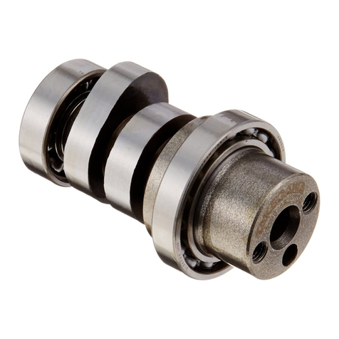
○A cam shaft for use with this kit is available from us.
Camshaft 01-08-042 Included in bore-up kits
COPY
‑A3‑ Dec./25/08
No. Part Name Qty Repair Part Item No. Qty
AIntake valve 114711-149-T02 1
BExhaust valve 114721-149-T02 1
CValve spring seat outer 200-01-0005 (SET) 2
DValve stem seal 200-01-0016 (SET) 2
EInner valve spring 2 2
FOuter valve spring 2 2
GValve cotter 400-01-0025 4
HValve spring retainer 214771-GB4-T00 1
IStud bolt 200-01-0073 2
01-12-0105 (SET)
No. Part Name Qty Repair Part Item No. Qty
1Cylinder head assembly 1SP/H-149-T101 1
2Exhaust pipe gasket 100-01-0027 2
Alumi Special (5 g) 100-01-0001 1
〜Kit Contents〜
∴Please order repair parts by indicating the numbers listed below. In some cases, we may not be able to accept your orders for
a component of the assembled unit. In this case, please order the required parts in units of sets.
Cylinder head inner parts
G
G
FF
I
HH
EE
DD
CC
A B
1
2
3-5-16 Nishikiorihigashi Tondabayashi Osaka Japan
TEL : 81-721-25-1357 FAX : 81-721-24-5059 URL : http://www.takegawa.co.jp
Co.,Ltd.

COPY
‑B1‑ Feb./15/07
◇Degrease the mating surfaces of
the cylinder and the cylinder head
with thinner.
◇Fix two dowel pins and a
cylinder head gasket to the
cylinder.
◇Pass the cam chain through the
cylinder head, and install the
cylinder head.
◇Pass the adjuster through the cam
chain tensioner and cylinder head
to attach it.
◇Temporarily tighten a set plate
with a locking bolt.
☆When installing a
camshaft:
◇Temporarily tighten a cylinder
head mounting bolt.
〜Installation Procedures of Cylinder Head〜
◇Loosen an adjusting nut on the
standard rocker arm attached to
the camshaft holder.
◇Remove a rocker arm from the
camshaft holder.
・Lightly screw 8mm bolt(s) to the
rocker arm shaft on the exhaust
side, and pull out the rocker arm
shaft.
・Push the inlet-side rocker arm
shaft with a screwdriver or the
like, and then remove the rocker
arm shaft.
◇Check the rocker arm shaft.
Service limit: 9.91 mm. Change the
rocker arm shaft of below this 9.91
mm.
◇After shaving off, check for any
burr, and clean up the camshaft
holder.
CAUTION: Do not shave off more
than needed.
CAUTION: Work with great care not
to give scratches to the
camshaft holder's
journal, and clamp faces
for the rocker arm and
the cylinder head.
◇Fix rocker arms into the cam shaft
holder.
・Apply engine oil to the notch on
the rocker arm shafts, and fix
them. At this point, align the notch
on the inlet rocker arm shaft with
a bolt hole on cam shaft holder,
and fix the rocker arm shafts. Also
fix the exhaust-side shaft with its
bolt hole facing outwardly.
◇Apply engine oil to the journal and
cam surfaces of the camshaft, and
install the camshaft to the cylinder
head with the cam shaft’s cam top
facing downwards.
◇Securely tighten the
temporarily-tightened cylinder
head mounting bolt.
Specified torque
: 12 N・m (1.2 kgf・m)
◇Check that "T" mark on the fly
wheel is aligned with the "▽"
mark on the crankcase.
◇Install the cam chain with the "O"
mark on the cam sprocket facing
upwards, and fit the cam sprocket
into the camshaft.
◇Remove an oil check bolt on the
standard cylinder head.
OIL
◇Attach two dowel pines and install
a camshaft holder.
◇Attach 4 washers and slightly
apply “Alumi Special”, the
heat-resistant lubricating agent, to
the seating faces of 4 nuts, and
equally tighten them up in a few
steps diagonally.
Specified torque
: 20 N・m (2.0 kgf・m)
Caution: Be sure to follow the
specified torque.
Caution: Be sure to follow the
specified torque.
Exhaust-siderockerarmshaft
Inletsiderocker arm
Cam surface
Journal
MO‑OIL
Dowelpins
“T”mark
100 Alignmentmark
50
Cylinderheadgasket
Dowelpins
NEW
◇Install the adjusting bolts and the
adjusting nuts, originally attached to
the stock rocker arm, to a supplied
rocker arm.
◇In case of there is no interference,
continue the installation work.
※If there is interference, modify the
camshaft holder and rocker arm by
rasping the interfering portions.
◇Check the camshaft holder and
rocker arm for the interference with
the camshaft.
(The supplied camshaft is designed
to have higher lift than a stock
camshaft. Some of the camshaft
holders and rocker arms may
interfere with the camshaft because
of the size difference of these parts.
So, never fail to check them for the
interference.)
◇Fit the provided camshaft into the
camshaft holder to see whether the
camshaft top, cam shaft holder and
rocker arm do not interfere with one
another.

COPY
‑B2‑ Feb./15/07
◇After tightening the nut, insert the
0.05mm thickness gauge again to
check the valve clearance.
◇Fill the oil reservoir on the cylinder
head with clean engine oil.
◇Install the cylinder head cover and
its gasket onto the cylinder head with
two cylinder head cover bolts.
Specified torque
: 12 N・m (1.2 kgf・m)
◇Now, you have completed the
cylinder head installation.
◇Referring to a genuie service
manual, install the engine to the
frame.
◇Install a carburetor, following the
installation procedures of the
carburetor kit.
◇Install a muffler, following the
installation procedures of the
exhaust muffler kit.
◇Holding the adjusting screw, tighten
the adjusting nut.
Specified torque
: 10 N・m (1.0 kgf・m)
※Cam chain adjustment:
◇Rotate the flywheel
counterclockwise till both cam
tops of the cam shaft come on
the top.
◇Turning the flywheel by hand,
feel the level of tension with the
cam sprocket. And turn the
flywheel up to the point where you
get the proper tension and you can
turn the flywheel freely withuot
sticking. At this point, tighten the
locking bolt and fix the adjuster.
◇In case you can not get the proper
tension of the cam chain only by
adjustment of the adjuster, then
adjust the tension with the adjusting
bolt on the cylinder.
Specified torque
: 12 N・m (1.2 kgf・m)
◇Adjust the valve clearance with an
adjusting screw.
IN :0.05 (when cold)±0.03
EX:0.05 (when cold) ±0.03
◇Holding a flywheel, tighten up two
hex bolts on the cam sprocket.
Specified torque
: 12 N・m (1.2 kgf・m)
◇Rotate the flywheel
counterclockwise until the "O" mark
on the cam sprocket is on the top
and the "T" mark on the flywheel is
aligned with the "▽"mark on the
crankcase.
◇Pour engine oil.
Amount: 1.0 litter
10W - 40 〜15W - 50
(Multigrade type)
Specified torque
: 10 N・m (1.0 kgf・m)
Omark
Blackbolt
◇Aligning the bolt hole on the
camshaft with the cam sprocket,
tighten two hex bolts loosely.
At this point, fix a knock bolt (black
bolt) on the intake side.
☆(In case of installing to an Ape- or
XR50 Motard-based motorcycle,
do be sure to use a cam sprocket
enclosed in the crank shaft.)
Caution: Be sure to follow the
specified torque.
Caution: Be sure to follow the
specified torque.
◇Attach a new sealing washer and
standard oil-check bolt to the
oil-check threaded hole, and tighten
them to the specified torque.
Specified torque
: 8 N・m (0.8 kgf・m)
☆Engine Starting
◇Check that the ignition key and the
fuel cock are turned off.
◇Apply "Alumi Special",heat-
resistant lubricating agent, a little
to the threaded portion of the
spark plug, and attach the spark
plug and tighten it to the specified
torque. Then attach a plug cap.
Specified torque:
10 N・m (1.0〜1.2 kgf・m)
◇Check for abnormal sounds.
◇If no problem is detected, do
running-in at leaset 100 to 150 km.
◇After the initial running-in, check
for abnormality such as abnormal
sounds or blow-bye.
(If there is a problem, disassemble
the engine again to check each
part.)
◇Please be sure to apply heatproof
lubricant agent like “Alumi Special”
slightly to the threaded portion of
a spark plug before
tightening it, particularly when the
spark plug is a new one.
Caution: Be sure to follow the
specified torque.
◇Turn on the gasoline cock and the
ignition key to start the engine.
Warning: Never reuse the piston
pin circlip.
◇Continue kicking the starter for a
while to circulate the engine oil
throughout the engine.
Warning: Be sure to do the work
in a well-ventilated
place.
Camtopsshouldbeonthetop
Caution: Be sure to follow the
specified torque.
Caution: Be sure to follow the
specified torque.
Caution: Be sure to follow the
specified torque.
Caution: Be sure to follow the
specified torque.
Caution: Be sure to follow the
specified torque.
Caution: Be sure to follow the
specified torque.
標準位置
張る
ゆるむ
ロックボルト
アジャスター
セットプレート
Adjuster
Setplate
Loosen
Standardposition
Tighten
Lockbolt

COPY
‑C1‑ Feb./15/07
〜Owner’s Manual〜
○Unit of torque:
1 kgf・m = 9.80665 N・m (newtonmeter)
Reference Value List for Cylinder Head
○Removal of Valve Cotter:
Use a magnet to remove a cotter if it doesn’t come off easily.
○Remove first the valve spring compressor, and then the following parts:
・Valve spring retainer
・Valve spring (Inner & Outer)
・Valve
○Valve Disassembly
Compress the valve spring using a valve spring compressor.
Caution: Never compress it more than necessary.
∴Special tools: Valve spring compressor kit: Item No. 00-01-1005
This cylinder head manual is prepared for those who have acquired basic skill and knowledge. Therefore, those who are technically
inexperienced or unskilled are requested not to do the installation work.
Warning
○Molybdenum solution →indicated as
This molybdenum solution is a mixture of molybdenum grease and engine oil in a ratio of 1:1.
∴Apply either molybdenum solution or assembly paste to the portion where application of molybdenum solution is specified.
MO‑OIL
○Parts to be replaced once every overwhaul are indicated as
These parts are those needing replacement at the time of every disassembly. So, please be sure to change these parts once
every disassembly.
NEW
Item Stock Service Limit Remarks
Valve clearance, IN 0.08±0.03mm(When cold)
Valve clearance, EX 0.08±0.03mm(When cold)
Distortion of cylinder head 0.05mm Replace
Internal diameter of valve rocker arm 10.000〜10.015mm 10.05mm Replace
External diameter of rocker arm shaft, IN/EX 9.978〜9.987mm 9.91mm Replace
Clearance between rocker arm and shaft 0.013〜0.037mm 0.10mm Replace
Internal diameter of valve guide, IN/EX 5.000〜5.012mm Replacement of either guide or head
External diameter of valve stem, IN 4.975〜4.990mm 4.92mm Replace
External diameter of valve stem, EX 4.952〜4.965mm 4.90mm Replace
Clearance beteen valve stem and guide, IN 0.01〜0.037mm
Clearance beteen valve stem and guide, EX 0.035〜0.06mm
Contacting width of valve seat, IN 0.8〜1.0mm 1.5mm Either modification or replacement of head
Contacting width of valve seat, EX 1.0〜1.2mm 1.7mm Either modification or replacement of head
Free length of valve spring, Outer 34.1mm 33mm Replace
Free length of valve spring, Inner 30.8mm 29.5mm Replace
○”Alumi Special”, the heat-resistant lubricating agent or paste is indicated as
・This “Alumi Special” is grease to protect parts from scoring or adhesion at high temperatures or under heavy weight.
(This chemical produces an effect especially when applied to hot sections of such parts as a spark plug and exhaust
manifold. )
☆Never apply this chemical to other portion than the specified ones.
AL‑SPL

COPY
‑C2‑ Feb./15/07
○Check every valve for bending, baking, and damage.
Measure the external diameter of the valve stem at the point, where it slides
against the guide, with a micrometer.
Replace the bent, scratched or damaged valve stem.
Service limit: for IN: 4.92 mm, for EX: 4.90 mm
Replace the bent, scratched or damaged valve stem with a new one.
○Inspection of Valve Spring Retainer
Replace it with a new one if its damaged.
○Inspection of Valve Seat:
・Remove carbon sediment in the cylinder head combustion chamber and
valve.
・Dissolve red lead primer with oil or the like, and apply it to the valve faces
evenly.
・Strike the valves once and lightly with a valve punner to rotate them.
・Wipe off the red lead primer on the valve faces, and strike the valves once
and lightly with the valve punner without rotating them, and inspect the
contact surfaces.
・If there is a scratch on the valve seat, modify the seat.
・If the contact width is wide, narrow, in a high or low position, modify the
seat.
・Ask a specialist shop in internal combustion for the modification work.
○Inspection of Rocker Arm:
Check the rocker arms for scratches, damages and jamming.
Measure the internal diameter of the rocker arms.
∴If the internal diameter is more than 10.05, replace the rocker arm.
Scratch on
the seat Slanted valve Contacting at
a low place Contacting at
a high place
Check this portion
for wearout

COPY
‑C3‑ Feb./15/07
○Inspection of Rocker Arm Shaft
・Check the rocker arm shaft for bending, scratches, and damages.
・Measure the external diameter of the rocker arm shaft.
∴ If the diameter is less than 9.91, replace it.
・Measure the clearance between the rocker arm and the rocker arm
shaft.
∴ If the clearance is more than 0.10, replace them.
○Inspection of Valve Spring:
・Check the valve springs for scratches and damages.
・Measure the free length of the valve springs.
∴Outer: If it is below 33, replace it. Inner: If it is below 29.5, replace it.
○Valve Assembly:
・Clean up the cylinder head.
・Fix valve spring seats and new valve stem seals.
・Apply molybdenum solution to the sliding surfaces of the valve stems,
and fit the valves into the valve guides, rotating valvles slowly with
care not to damage the stem seals.
○Inspection of Cam Shaft:
・Check the cam shaft for scratches, cracks, and damages.
・Measure the height of cam tops.
Check here for scratches,
cracks, and damages.
Whentheouterfreelengthofvalve
spring is below 33, change it.
Whentheinnerfreelengthof
valve spring is below 29.5,
changeit.
Valve
Valvecotter Valvecotter
Valvespring, outer
Valvespring retainer Valvespringretainer
Valve
MO‑OIL
Stemseal NEW Stemseal NEW
Valvespring, inner
Springseat,outer Spring seat,outer
Valvespring, outer
Valvespring, inner
・Attach the valve spring, with narrower pitch pointing to the combustion
chamber side.
CAUTION: Be sure to place a valve spring with the narrower pitch to
face the combustion chamber side.
・Compress the valve spring with a valve spring compressor. Apply grease
a little to valve cotters, and attach the valve cotters.
CAUTION: Do not compress the valve spring more than necessary.
・Strike the tops of valve stems a few times so the valves and cotters fit
together well.
CAUTION: Be careful not to damage the valves.
Narrowerpitch
Combustionchamber
IN EX
Camshaft Below 28.4 Below 28.4 Replace

COPY
Jan./17/07
SuperHeadkit
01―03―0741
カムを選択
Selecta cam
シリンダーを選択
Select a cylinder
STD
Racing
01―04―1005
01―04―1011
クランクケース加工必要
ボアアップ 参照表(115cc)
Reference data on bore-up (115cc)
(STAGE―1)
57φcylinder kit
57φplated cylinder kit for racing
Crankcases need processing.
☆01―03―0741シリンダーヘッドのみで購入された場合、この参照表にてボアアップパーツを検討して下さい。(ノーマルクランク使用時)
☆
If you have purchased a cylinder head only (Item No. 01-03-0741), please study to purchase parts for bore-up referring to this reference data.(In the case of using a stock crank)
(Ape100、XR100MOTRD、XR100R、CRF100F)
(◎ストロークアップクランクを使用する際も各シリンダーキットは共通で使用出来ます。裏面のボアストロークアップ参照表を参照下さい。)
(◎In case the stroke-up crank is used, these cylinder kits can be used. Please see the attached “Reference data on bore- & stroke-up kit.”)
01―08―042

COPY
Jan./17/07
☆01―03―0741シリンダーヘッドのみで購入された場合、この参照表にてボア&ストロークアップパーツを検討して下さい。
☆If you have purchased a cylinder head alone (Item No. 01-03-0741), please study to purchase bore- and stroke-up parts referring to this reference data.
(Ape100、XR100MOTRD、XR100R、CRF100F)
カムを選択
Selecta cam
STD
Racing
クランクケース加工必要
01―03―0741
01―04―1005
01―04―1011
01―10―0112
SuperHeadkit
シリンダーを選択
Select a cylinder
57φcylinder kit
57φplated cylinder kit for racing
Crankcases need processing.
Stroke- upcrank shaftkit
01―08―042
Reference data on bore- & stroke-up kit (124cc)
(STAGE―1)
ボア&ストロークアップ参照表(124cc)

COPY
Jan./17/07
Reference data on bore- & stroke-up kit (124ccc)
(STAGE―1)
ボア&ストロークアップ参照表(124cc)
☆01―03―0741シリンダーヘッドのみで購入された場合、この参照表にてシリンダーキットとクランクシャフトキットをお選び下さい。
☆If you have purchased a cylinder head alone (Item No. 01-03-0741), please select a cylinder and crank shaft kits referring to this reference data.
(Ape、XR50MOTRD)
☆Ape、XR50MOTRDで使用する場合、上記パーツが必要となります。
☆In case this kit is to be installed onApe and XR50 Motard, the above-mentioned parts are needed.
☆クランクケース加工が必要です。
☆Crank cases need processing.
カムを選択
Selecta cam
01―04―1005 01―10―0102
01―03―0741
SuperHeadkit
57φcylinder kit Stroke- upcrank shaftkit
01―08―042

COPY
Jan./17/07
☆01―03―0741シリンダーヘッドのみで購入された場合、この参照表にてボアアップパーツを検討して下さい。(ノーマルクランク専用)
(Ape100、XR100MOTRD、XR100R、CRF100F)
スーパーヘッドキット
01―03―0741
カムを選択
Selecta cam
排気量を選択
136cc
125cc
SCUTシリンダーキット59.4φ
01―04―1014
SCUTシリンダーキット62φ
01―04―1013
superheadkit
Select engine displacement
SCUT Cylinder Kit, 59.4φ
SCUT Cylinder Kit,62φ
☆If you have purchased a cylinder head only of Item No. 01-03-0741, please study to purchase parts for bore-up referring to this reference list.
(exclusivsely for a stock crank)
(Ape100, XR100MOTRD, XR100R, CRF100F)
ボアアップ 参照表(SCUT 125cc、136cc)
Reference data on bore-up (SCUT 125cc,136cc)
01―08―042
Table of contents
Other Takegawa Motorcycle Accessories manuals

Takegawa
Takegawa PC20 User manual

Takegawa
Takegawa 02-01-0284 User manual

Takegawa
Takegawa Mikuni VM26 User manual

Takegawa
Takegawa Hyper S-stage User manual

Takegawa
Takegawa 09-12-1010 User manual

Takegawa
Takegawa 09-03-0708 User manual

Takegawa
Takegawa 02-01-0205 User manual

Takegawa
Takegawa KEIHIN PD22 User manual

Takegawa
Takegawa 02-01-0016 User manual

Takegawa
Takegawa 02-01-0281 User manual