manuals.online logo
Brands
  1. Home
  2. •
  3. Brands
  4. •
  5. Takegawa
  6. •
  7. Motorcycle Accessories
  8. •
  9. Takegawa PC20 User manual

Takegawa PC20 User manual

COPY
2022.2.7 /2
03-05-0243,03-02-06
Big Carburetor Kit (PC20) Instruction manual
◎ The use of ignoring the instructions that are written in the instruction manual, if an accident or damage has occurred, we can not
 assume any responsibility for compensation.
◎ This product installation and use, when a problem occurs to after market goods, guarantee other than this product, also can not
 assume any in any such matters.
◎ If it was the case or mounting that has been processed like a product, it will not be covered under warranty.
◎ It is not possible to inquire of the combination of other manufacturers.
◎ Please note that this Kit is designed for exclusive use in the YB-Four equipped with S-Stage, and that it cannot be mounted on
 motorcycles with a standard engine or any other motorcycle models.
◎ When ordering repair parts, please quote Item Nos above and reference Nos in the 󲶻gures in this Manual. Should you have any
 questions about the Kit,please kindly contact your local motorcycle dealer.
◎ A standard mirror cannot be installed onto a supplied general-use brake lever & holder. Please separately purchase a mirror of M0x.25.
Adaptation model YB-Four
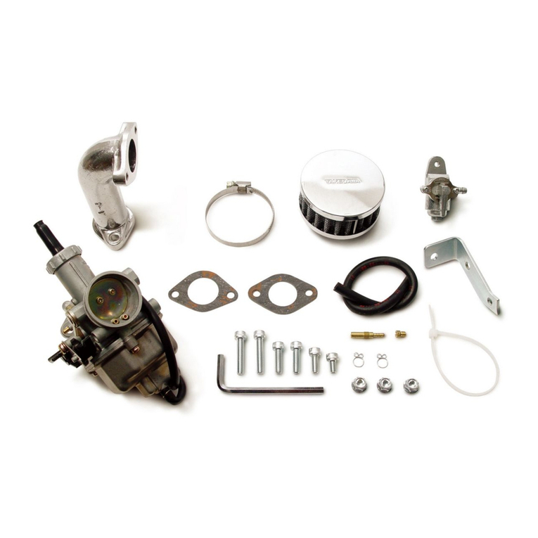
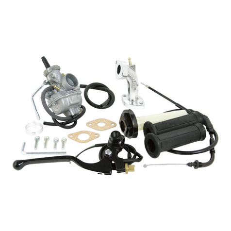
Number Product content Quantity Item Number
  Carburetor ASSY.  03-03-0077
※ 2 Intake manifold COMP.  00-00-472
※ 3 Intake manifold gasket  00-0-059 (2pcs)
※ 4 Carburetor gasket  00-03-047
※ 5 Socket cap screw, 6x20 2 00-00-072 (5pcs)
※ 6 Socket cap screw, 6x25 2 00-00-0722 (5pcs)
 7 Funnel spacer  00-00-457
 8 Standard High Throttle Kit  09-02-0222
 9 Brake lever & Holder  06-08-3002
 0 Fuel tube  00-03-0203 (500mm)
※  Hex wrench, 5mm 
①
④③
②
⑤ ⑦⑥
⑧
⑨
⑪
⑩
Product number 03-05-0243 (Carburetor kit)
03-02-06 (Manifold set)
Thank you very much for purchasing our products.
Thank you so you will comply with the following matters at the time of use.Before installation, please check your always kit contents.
If there is a point of notice event, Please contact us the dealer of purchase.
◎ If the description, such as photos or Illustration different with this part.
☆ Please read carefully before use ☆
Caution When the handling of ignoring this display, property damage and human shows the assumption of what injury.
Warning When the handling of ignoring this display people died, shows the contents of the serious injury possibility is
assumed.
■ Always try to drive your motorcycle at legal speed on public roads, abiding by the laws.
■ Work only when the engine and muf󲶼er are cool. (Otherwise, you will get burned.)
■ Do the installation with right tools. (Otherwise, breakage of parts or injuries to you may take place.)
■ Always use a torque wrench to screw bolts and nuts tight and securely to the speci󲶻ed torque.
 (Otherwise, these parts may get damaged or fall off, resulting in accidents.)
■ As some products and frames have sharp edges or protruding portions, please work with your hands protected.(Otherwise, you will suffer injuries.)
■ Before riding, always check every hardware like screws for slack. If you 󲶻nd slack ones, screw them securely up to the speci󲶻ed torque.
 (Otherwise, improper tightening may cause parts to come off.)
■ Always use new gaskets and packings. And check those parts, to be reused, for wear and damage. If you 󲶻nd worn or damaged parts,
 replace them with new ones.
■ If you start the engine, be sure in a well-ventilated place. In the sealed such place, please do not start the engine.
(There is a risk of carbon monoxide poisoning.)
■ During operation, when an abnormality occurs, immediately stop the vehicle in a safe place, please stop running.(It may lead to an accident.)
■ When performing the work, do the work safely stabilize the vehicle in a horizontal location.
 (There is a risk of injury vehicle collapsed while working.)
■ Inspection, maintenance, the instruction manual or, inspection methods such as service manuals, to protect the way, should be done
 correctly.(unsuitable inspection and maintenance, there is a risk that result to an accident.)
■ When carrying out the inspection and maintenance, etc., if found damaged parts, replace the damaged parts to avoid possible to reuse
 the parts. (There is a risk that lead to accidents Continued use.)
■ Plastic bags of product packaging, you can either be stored in a place that is out of reach of children, it should be discarded.
 (When the children or wearing, there is a risk of suffocation.)
■ As gasoline is highly 󲶼ammable, never place it close to 󲶻re. Make sure that nothing 󲶼ammable is near the gasoline. Since vaporized
 accumulation of gasoline is at high risk of explosion, work in a well-ventilated place. (Otherwise it may cause a 󲶻re.)
◎ Please note. Performance up, the design change, the product and the price in the cost up, etc. are subject to change without notice.
◎ Please be informed that we shall be held harmless against any claim against us whatsoever arising out of use of the products in
 racing and the like.
◎ Keep this manual stored until this product is discarded.
CONTACT Address : 3-5-6 Nishikiorihigashi Tondabayashi Osaka JAPAN
TEL: +8-72-25-357 FAX:+8-72-24-5059 e-mail:[email protected] URL http://www.takegawa.co.jp
Please contact with your name and country name provided. (Only English please)
※ means the parts are a part of a manifold set.
∴ Please order in the repair parts are always repair part number.
 If it is not the part number order, you may not be able to order.
 Please be forewarned.
 It should be noted, In the case of parts that can not be separately
 shipment, please order a set part number.
Product content
COPY
2/2
03-05-0243,03-02-06
2022.2.7
Removal of carburetor:
○ Place an intake manifold gasket between a
 supplied intake manifold and cylinder head,
 and join them together by tightening 6x20
 socket cap screw.
○ Place a carburetor gasket between a
 supplied intake manifold and the carburetor,
 and secure them together with 6x25 socket
 cap screws to the speci󲶻ed torque.
○ Remove a top cap from the carburetor, and
 pull out a spring and throttle valve.
 And 󲶻x these parts into the throttle cable.
○ Align the notch on the throttle valve with
 the direction of the throttle stop screw,
 and then install it to the carburetor.
 Align the convex section on the top cover
 with the concave section on the carburetor.
※ Snap the throttle a few times to check
 how much the throttle valve opens and closes.
○ Set the fuel cock at PRI and check every
 hardware for oil leak.
○ Set the fuel cock at either ON or RES.
○ Pull a choke lever to start the engine,
 and check every hardware for intake air leak.
 Gradually loosen your grip on the choke
 lever, and warm up the engine till the
 revolution becomes smooth.
 And then return the choke lever fully
 back to its original location.
 If the engine does not run idle after
 warming-up, or it runs idle at high  
 revolutions, adjust the revolutions with
 the throttle stop screw.
◇ Adjust the setting with utmost care in a
 safe place to meet the speci󲶻cation of
 each motorcycle.
Make sure your motorcycle is secure
on a maintenance stand on level and
safe ground.
○ Check that the fuel cock lever is at
 either ON or RES.
○ Remove the left side air cleaner case
 cover.
○ Pull out a breather hose from the air
 cleaner case, and detach the air cleaner
 case by loosening the joint clamp screw.
○ Disconnect hoses and heater lead cord.
 At this time, insulate the heater lead
 cord with a vinyl tape.
○ Remove the choke lever from the motorcycle.
○ Remove the carburetor unit and inlet
 pipe from the engine.
RES
ON
Joint clamp screw
Referring to the instruction manuals
for the high throttle and brake lever,
install them to the steering handle.
Installation of carburetor:
Socket cap screw,6x20
○ Attach a funnel spacer to the tip of the
 carburetor.
Funnel spacer
Negative pressure hose
Notch
Throttle stop screw
○ Unfasten a screw which is holding the
 lever holder, and detach it from the
 steering handle.
Removal of lever holder:
○ Adjust the free play at the throttle grip to
 be about 5mm by adjusting the throttle cable.
○ Attach a stock air cleaner case, and
 tighten up a joint clamp screw.
○ Connect a breather hose to the air
 cleaner case.
○ Connect the fuel hose and negative
 pressure hose.
Joint clams screw
Breather hose
Negative pressure
Fuel
■ Mounting procedure ※ Please refer to the Genuine Service Manual for detailed mounting methods and speci󲶻ed torques that are not
             speci󲶻cally described.
  Note: Be sure that you protect speci󲶻ed
    torque.
Socket cap screw
 Torque:0N・m(.0kgf・m)
  Note: Be sure that you protect speci󲶻ed
    torque.
Socket cap screw
 Torque:0N・m(.0kgf・m)
Socket cap screw,6x25
COPY
2022.2.2
 ○ Main jet (The throttle position at 3/4 - 4/4)
 How to Set the Carburetor
・When the carburetor does not match the engine and the engine fails, the engine failures are caused by either too dense or too lean
 air-fuel mixture.
・The engine failure symptoms for the engine are as follows:
When the air-fuel mixture is too dense: When the air-fuel mixture is too lean:
 ・The explosion sound with a dull thud continues
  intermittently.
 ・The engine malfunctions further if you use the choke.
 ・The engine malfunctions when you warm it up.
 ・The engine works well if the cleaner is detached.
 ・The motorcycle belches dense (or, black) exhaust gas.
 ・The plug smolders, getting blackened.
 ・The engine overheats somewhat.
 ・The engine starts working well If you use the choke,.
 ・The engine does not accelerate well.
  (No smooth acceleration)
 ・Revolutions change, generating weak power.
 ・The plug burns white.
※ Set the carburetor only after warming up the engine, and then test-drive. And use a plug with the right heat value.
※ Do the setting in the following manner, studying at what throttle opening position the engine starts failing.
   ・The air-fuel mixture ratio at this throttle position can be adjusted by changing the number of the main jet. The larger the  
    main jet numbers, the denser the mixture ratio becomes.
   ・In view of the engine and muf󲶼er speci󲶻cations, select the most appropriate main jet to get the highest revolutions.
 ○ Slow jet / Pilot jet (First of all, please adjust the air screw.)
   ・In case you have given more than three turns to the air screw to tighten it, use a slow jet / pilot jet with a small number.
   ・If you have tighten the air screw (clockwise) to the full, use a slow jet / pilot jet with a larger number.
    Check whether you have made a right choice of the pilot jet by seeing if the engine starts up revolving smoothly from the
    idling to running at slow speed.
   ・When the engine revolves up unevenly, the slow jet / pilot jet number is too small. (At idle)
   ・When the motorcycle belches black exhaust gas and produces heavy exhaust sound, the slow jet / pilot jet number is too big. (At idle)
   ・After replacing the slow jet / pilot jet, you need to readjust the airscrew.
 ○ Air screw
   The air screw adjusts the air mass 󲶼ow at the time of engine’s revolving at slow speed. (At idling)
   ・Give the air screw a right turn → The air-fuel mixture gets dense.
   ・Give the air screw a left turn → The air-fuel mixture gets lean.
   Loosen the tightened air screw back to the 1.5-turn position. And then from this position, give to the airscrew a right or left
   turn of 1/4 to 1/2 till the engine revolves at the highest speed.
   Loosen the idle stop screw till you get the steady idling revolutions. And once again adjust the position of the airscrew to get
   the highest revolutions.
● On how the barometric pressure, temperatures and humidity affect the setting:
   ・At highlands or at high altitudes, the barometric pressure and air density go down and the air gets into the carburetor in less
    amounts.
    This makes the air-fuel mixture dense which was adjusted at low altitudes.
   ・Under the weather conditions with very low temperatures, the air density increases, which makes the air-fuel mixture lean.
   ・Under the rainy and humid weather conditions, the air density decreases, which makes the air-fuel mixture dense.
 ○ Jet needle (Throttle position at 1/4 - 3/4)
   Whether or not the engine revolution is in proportion to the throttle operation
   ・When the acceleration is not smooth or even, make the air-fuel mixture dense.
   ・Make the air-fuel mixture lean when the engine revolution goes up heavily and belches black gas.
   The mixture ratio at this throttle position can be adjusted by the location of E-ring in the grooves. The air-fuel mixture
   becomes dense as the location of the E-ring moves down from the 1st to the 5th groove.
1st groove
2nd groove
3rd groove
5th groove
4th groove
CONTACT Address : 3-5-16 Nishikiorihigashi Tondabayashi Osaka JAPAN
TEL: +81-721-25-1357 FAX:+81-721-24-5059 e-mail:[email protected] URL http://www.takegawa.co.jp
Please contact with your name and country name provided. (Only English please)

This manual suits for next models

2

Other Takegawa Motorcycle Accessories manuals

Takegawa 09-03-0708 User manual

Takegawa

Takegawa 09-03-0708 User manual

Takegawa 02-01-0205 User manual

Takegawa

Takegawa 02-01-0205 User manual

Takegawa PC20 User manual

Takegawa

Takegawa PC20 User manual

Takegawa TwinSpark Super head plus R User manual

Takegawa

Takegawa TwinSpark Super head plus R User manual

Takegawa 02-01-0281 User manual

Takegawa

Takegawa 02-01-0281 User manual

Takegawa Super head STAGE-1 kit User manual

Takegawa

Takegawa Super head STAGE-1 kit User manual

Takegawa 03-05-0020 User manual

Takegawa

Takegawa 03-05-0020 User manual

Takegawa 09-12-1010 User manual

Takegawa

Takegawa 09-12-1010 User manual

Takegawa 02-01-0016 User manual

Takegawa

Takegawa 02-01-0016 User manual

Takegawa KEIHIN PD22 User manual

Takegawa

Takegawa KEIHIN PD22 User manual

Takegawa Mikuni VM26 User manual

Takegawa

Takegawa Mikuni VM26 User manual

Takegawa Hyper S-stage User manual

Takegawa

Takegawa Hyper S-stage User manual

Takegawa Operation and Instruction Manua Guide

Takegawa

Takegawa Operation and Instruction Manua Guide

Takegawa 01-08-0127 User manual

Takegawa

Takegawa 01-08-0127 User manual

Takegawa 09-07-2711 User manual

Takegawa

Takegawa 09-07-2711 User manual

Takegawa 02-01-0284 User manual

Takegawa

Takegawa 02-01-0284 User manual

Popular Motorcycle Accessories manuals by other brands

Arai Helmet GP-5X instruction manual

Arai Helmet

Arai Helmet GP-5X instruction manual

Yoshimura Street Series manual

Yoshimura

Yoshimura Street Series manual

Petzl VERTEX VENT A11 manual

Petzl

Petzl VERTEX VENT A11 manual

Noam NMC3 user manual

Noam

Noam NMC3 user manual

Big Gun Exhaust EVO U Series Installation instruction sheet

Big Gun Exhaust

Big Gun Exhaust EVO U Series Installation instruction sheet

Petzl VERTEX VENT manual

Petzl

Petzl VERTEX VENT manual

hepco & becker 506998 00 01 quick start guide

hepco & becker

hepco & becker 506998 00 01 quick start guide

MotoChello MC-100 user guide

MotoChello

MotoChello MC-100 user guide

hepco & becker 6307596 00 01 manual

hepco & becker

hepco & becker 6307596 00 01 manual

gilles.tooling VCR38GT owner's manual

gilles.tooling

gilles.tooling VCR38GT owner's manual

LSL K12R FITTING INSTRUCTION

LSL

LSL K12R FITTING INSTRUCTION

TERMOSCUD R240 PRO instruction manual

TERMOSCUD

TERMOSCUD R240 PRO instruction manual

Suzuki 99116-48K00-000 installation instructions

Suzuki

Suzuki 99116-48K00-000 installation instructions

hepco & becker 650989 00 02 manual

hepco & becker

hepco & becker 650989 00 02 manual

hepco & becker 810669 00 12 quick start guide

hepco & becker

hepco & becker 810669 00 12 quick start guide

Sena Outstar S user guide

Sena

Sena Outstar S user guide

Malossi W 450XH 350 THK 3 MM Assembly instructions

Malossi

Malossi W 450XH 350 THK 3 MM Assembly instructions

Suzuki 990D0-04K60-CRB Mounting instructions

Suzuki

Suzuki 990D0-04K60-CRB Mounting instructions

manuals.online logo
manuals.online logoBrands
  • About & Mission
  • Contact us
  • Privacy Policy
  • Terms and Conditions

Copyright 2025 Manuals.Online. All Rights Reserved.