Tar River EMF Guide

1
3 Pt. Flail Mowers
EMF & EFGC
Operation and Parts Manual
Rev. 01/22

2
TO THE CUSTOMER
This manual contains valuable information about your new mower. It
has been carefully prepared to give you helpful suggestions for operating,
adjusting and servicing.
Keep this manual in a convenient place for quick and easy reference.
Study it carefully, only by proper care and operation can you expect to re-
ceive the service and long life designed and built into this mower.
It is the owner’s and\or operator’s responsibility to…
•
Read and understand the information contained in this
manual.
•
Operate, lubricate, assemble and maintain the equipment in accord-
ance with all instructions and safety procedures in this manual.
•
Inspect the equipment and replace or repair any parts that are dam-
aged or worn which could cause damage, wear to other parts, or
cause a safety hazard.

3
TABLE OF CONTENTS
DESCRIPTION PAGE NUMBER
SAFETY INSTRUCTIONS
4
SAFETY TRAINING
5
STARTING AND STOPPING SAFETY
5
OPERATION SAFETY
6
TRANSPORT SAFETY
6
SERVICE AND MAINTENACE SAFETY
7
STORAGE SAFETY
7
SAFETY SIGNS
8
ASSEMBLY
9
ATTACHING TO THE TRACTOR
10
OPERATION
11
MAINTENANCE
13
PARTS BREAKDOWN
15-35
WARRANTY
21

4
SAFETY INSTRUCTIONS
Good safety practices not only protect you, but also the people around you. Make these
practices a working part of your safety program. Be certain that everyone operating this equip-
ment is familiar with the recommended operating and maintenance procedures and follows all
the safety precautions. Most accidents can be prevented. Do not risk injury or death by ignoring
good safety practices.
The alert symbol is used throughout this manual. It indicates attention is required and
identifies hazards. Follow the recommended precautions.
The safety alert symbol means…
ATTENTION! BECOME ALERT! YOUR SAFETY IS INVOLVED!
CAUTION
The caution symbol indicates a potentially hazardous situation that, if not avoided, may
result in minor or moderate injury. It may also be used to alert against unsafe practices.
WARNING
The Warning Symbol indicates a potentially hazardous situation that, if not avoided,
could result in death or serious injury, and includes hazards that are exposed when
guards are removed. It may also be used to alert against unsafe practices.
DANGER
The Danger Symbol indicates an imminently hazardous situation that, if not avoided
will result in death or serious injury. This signal word is to be limited to the most extreme situa-
tions, typically for machine components that, for functional purposes, cannot be guarded.

5
TRAINING SAFETY
Safety is a primary concern in the design and manufacture of our products. Unfortunate-
ly, our efforts to provide safe equipment can be wiped out by a single careless act of an opera-
tor.
In addition to the design and configuration of equipment, hazard control and accident
prevention are dependent upon the awareness, concern, prudence and proper training of person-
nel involved in the operation, transport, maintenance and storage of equipment.
It is the operator’s responsibility to read and understand ALL Safety and Operating instructions
in the manual and to follow them. Accidents CAN be avoided.
Working with unfamiliar equipment can lead to careless injuries. Read this manual and
the manual for your tractor before assembling or operating your mower, to acquaint yourself
with the machines. It is the finish mower owner’s responsibility if this machine is used by any
person other than yourself, to make certain that the operator, prior to operating:
•
Reads and understands the operator’s manuals.
•
Is instructed in safe and proper use.
Know the controls and how to stop tractor, engine, and mower quickly in an emergency.
Read this manual and the one provided with your tractor.
Train all new personnel and review instructions frequently with existing workers. A per-
son who has not read and understood all operating and safety instructions is not qualified to op-
erate the machine, An untrained operator exposes himself and bystanders to possible serious
injury or death.
Do not allow children to operate this machine.
STARTING AND STOPPING SAFETY
Mower operating power is supplied from tractor PTO. Refer to your tractor manual for
PTO engagement and disengagement instructions. Always operate the tractor PTO in the 540
rpm speed selection. DO NOT OVER SPEED! Know how to stop tractor and mower quickly in
case of an emergency.
When engaging PTO, the engine RPM should always be low. Once engaged and ready
to start cutting, raise PTO speed to approx. 540 RPM and maintain throughout cutting opera-
tion.
Always stop the tractor, set brake, shut off the tractor engine, remove the ignition key,
lower implement to the ground and allow cutter blades to come to a complete stop before dis-
mounting tractor. Never leave equipment unattended with tractor running or with imple-
ment in raised position.

6
OPERATION SAFETY
The use of this equipment is subject to certain hazards which cannot be protected
against by mechanical means or product design. All operators of this equipment must read and
understand this entire manual, paying particular attention to safety and operating instructions,
prior to using. If there is something in this manual you do not understand, ask your supervisor,
or your dealer, to explain it to you.
Most accidents occur because of neglect or carelessness. Keep all helpers and bystand-
ers at least several hundred feet from an operating finish mower. Only properly trained people
should operate this machine.
When this machine is operated in populated areas or in other areas where thrown objects
could injure persons or property, standard equipment safety chain shielding (which is designed
to reduce the possibility of thrown objects) must be installed. Operation must be stopped
when anyone comes within 100 yards(300feet).
The majority of accidents involve entanglement on the driveline, injury of bystanders by
objects thrown by the rotating blades, and operators being knocked off the tractor by low hang-
ing limbs and then being run over by the mower. Accidents are most likely to occur with ma-
chines that are loaned or rented to someone who has not read the owner’s manual and is not fa-
miliar with a finish mower.
Check the tractor master shield over the PTO shaft. Make sure it is in good condition
and fastened securely to the tractor. Purchase a new shield if old shield is damaged or missing.
TRANSPORT SAFETY
Review Transport Safety instructions in tractor manual before moving.
Check with local authorities regarding transport on public roads. Obey all applicable
laws and regulations.
Make sure the SMV (Slow Moving Vehicle) emblem and all the lights and reflectors that
are required by the local highway and transport authorities are in place, are clean, and can be
seen clearly by all overtaking and oncoming traffic.
Never have the equipment in operation during transport.
Always travel at a safe speed.
Inflate transport tires to recommended pressure.
Do not drink and drive!

7
SERVICE AND MAINTENANCE SAFETY
Stop engine, set brake, remove ignition key, and wait for all moving parts to stop before
servicing, adjusting, repairing, or unplugging.
Support the equipment with blocks or safety stands before working beneath it.
Follow good shop practices including:
-Keep service area clean and dry
-Be sure electrical outlets and tools are properly grounded
-Use adequate light for the job
Use only tools, jacks, and hoists of sufficient capacity for the job. Replace and secure all
shields removed during servicing before operating. Use heavy leather gloves to handle sharp
objects.
Failure to follow proper procedures when mounting a tire on a wheel or rim can produce
an explosion, which may result in serious injury or death.
Do not allow grease or oil to build up on any deck or platform.
Where replacement parts are necessary for periodic maintenance and servicing, genuine
factory replacement parts must be used to restore your equipment to original specifications.
The manufacturer will not claim responsibility for use of unapproved parts and/or
accessories and other damages as a result of their use.
If equipment has been altered in any way from original design, the manufacturer does
not accept any liability for injury or warranty.
A fire extinguisher and first aid kit should be kept readily accessible while performing
maintenance on this equipment.
STORAGE SAFETY
Following operation, or when unhooking, stop the tractor, set the brakes, disengage the
PTO, shut off the engine and remove the ignition keys.
Store the unit in an area away from human activity.
Do not permit children to play on or around the stored machine.
Make sure all parked machines are on a hard, level surface and engage all safety
devices. Support the frame on stands and blocks to provide a secure base.

8
SAFETY SIGNS
Keep safety signs clean and legible at all times.
Do not paint over, remove or deface any safety signs or warning signs on your
equipment.
Observe all safety signs and practice the instruction on them.
Replace safety signs that are missing or have become illegible.
Replaced parts that displayed a safety sign should also display the current sign.
Safety signs are available from your place of purchase.
The safety signs used on the mower and their location are shown on the following sheet
along with the part number for the safety signs.

9
EFM
ASSEMBLY
•
Carefully remove all parts from crate
•
Install A Frame as Shown:
Lower A Frame straps bolted inside the hitch block brackets
The assembly for the upper A frame section, see below
•
Install Front and Rear Guards
EFGC
•
Carefully remove all parts from crate
•
Install A Frame as Shown
•
Install Front and Rear Guards

10
ATTACHMENT TO THE TRACTOR
Carefully read this instruction manual and the manuals of the tractor to ensure all safety pre-
cautions are taken . All mowers are built to be attached to any tractor equipped with a three-point lift
of the correct category and with suitable ball ends.
Before attaching the equipment to the tractor, make sure that the ground is smooth and flat and
that nobody is standing between the tractor and the mower; slowly move the tractor towards the mow-
er by aligning the tractor lifter arms with the two mower coupling side pins; turn the engine off and
pull the brake.
Connect the tractor top link to the third upper point by removing the pin located between the
two plates, inserting the top link and securing it by means of the pin.
Adjust the top link so that the upper part of the frame is parallel to the ground.
Block all the linking parts by means of the sway chains or arms.
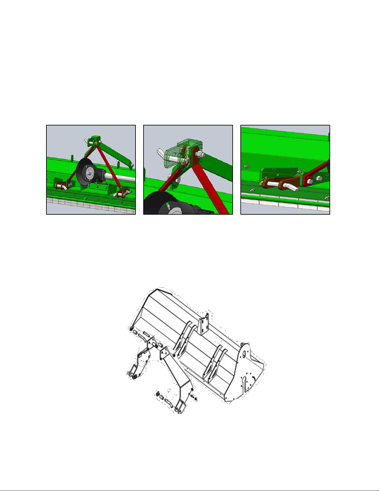
•
Connect Hydraulic Quick Connect Couplings to Tractor.
•
Remove Locking Pivot Pin.
•
Remove Locking Angling Pin.
•
Adjust Hydraulic flow Control.
Before installing the PTO shaft make sure that the RPM rating and the direction of rotation
match those of the tractor. Carefully read the PTO shaft and tractor instructions.
Furthermore, accurately read the instructions of the manufacturer of the PTO shaft and of the tractor.
Before starting any activity, make sure that the guards are installed on the power take off of the tractor
and PTO shaft. Make sure that they cover the PTO shaft throughout its length.
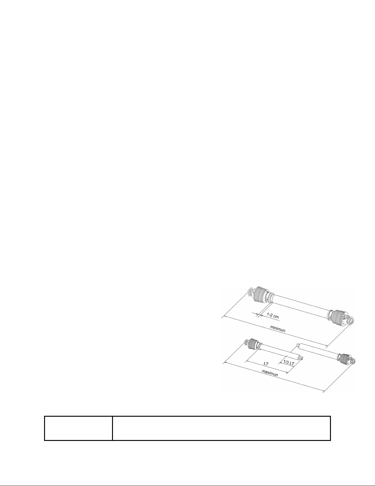
Shortening a PTO Driveline
1. With the implement attached to the tractor’s three point
hitch, and the PTO driveline not installed, separate the
PTO driveline. Attach the implement end to the imple-
ment and the other end to the tractor PTO input shaft.
2. Raise the implement by using the tractor’s hydraulic 3-
point hitch to it’s maximum lift height.
3. Hold the half shafts next to each other and mark them so
each end is approximately ½” from hitting the end of the
telescopic profiles.
4. Shorten the inner and out guard tubes equally.
5. Shorten the inner and outer profiles by the same length as
the guard tubes. Using a rattail file, round off all sharp
edges and burrs. Grease the telescopic profile generously
before reassembling.
CAUTION When fully extended, the plastic pipes must overlap by at
least 1/3 of the length of the pipes (LT). When retracted, the
min. acceptable clearance is 1-2 cm.

11
OPERATION
Before beginning:
•
Check Oil level in Center Gearbox
•
Check Oil Level in Drive Tube
•
Check Belt Tension
•
Rotor Bearings on both side
•
Check PTO length (See PTO Section)
CUTTING HEIGHT ADJUSTMENT
The cutting height of the equipment depends on
the position of the rear Roller. Set both sides at the same
height.
To adjust the cutting height on the mowers loos-
en pivot bolt (do not remove) and reposition the bolts
holding the Roller to the desired height.
Adjusting Belt Tension
In the mowers it is necessary to adjust the belt tension as they stretch; the correct belts
tensioning ensures that the machine works
correctly.
To adjust the belts tension:
•
Remove the belt shielding.
•
Loosen (do not remove) the hardware hold-
ing the gearbox and tube support in place.
•
Tighten the belts by turning the nut on belt
adjustment plate and tube support.
•
Retighten the gearbox support and the tube support hardware.

12
MAINTENANCE
Maintenance is crucial for the working life and efficiency of any agricultural equipment. If
the equipment is properly maintained and operated, a long working life and operator safety are
assured.
The maintenance intervals indicated in this booklet are provided as a mere reference and are
related to normal working conditions; some changes may occur depending on the type of activities,
environmental dust, and seasonal factors, etc.
Before beginning:
Check the oil level in the center gearbox and drive support tube and grease the rotor bearings.
After 8 Hours:
Check the oil level in the center gearbox
Check the hardware for tightness. Tighten as necessary.
After 30 hours:
Check the hardware for tightness. Tighten as necessary.
Check the belt tension and inspect for wear
Left: Center Gearbox
Right: Drive Tube
Left: Left Rotor Bearing
Right: Right Rotor Bearing

13
M-THREADED SCREW/BOLTS
Bolt grade
TORQUE SPECIFICATION
For the correct hardware torque on the mower, we suggest the use of suitable torque wrench
and the applicable torque as listed in the table below:
Thread
8.8
10.9
Nm
Lb-ft
Nm
Lb-ft
M6
11
8.5
17
12
M8
28
20
40
30
M10
55
40
80
60
M12
95
70
140
105
M14
150
110
225
165
M16
240
175
305
225
M18
330
250
475
350

14

15
Parts
Breakdown
BCRL
BCRM

16
Flail Mower
EFM

No
Part Number
Description
Office Use Only
QTY
1
BCM206
Bushing- (Cat 2) for upper hitch
21.084.059
1
2A
BCM208
Hitch pin- Lower
03.31.01.041
2
2B
BCM207
Hitch pin- Upper
03.31.01.040
1
3
EM104
Chain for hanging PTO shaft
04.17.006
1
4
EM105
Chain Lock
04.98.003
2
5
BCM209
Bushing- Lower Hitch
21.002.011
2
6
LYNPN10
Lynch pin- M10
03.35.008
3
7
EM107
Lower Hitch
26.016.013
2
8
LNM1620
Self-locking nut- M16
03.14.006
37
9
BM162070
Bolt- M16 x 2.0 x 70
03.18.04.015
4
10
BM1620100
Bolt- M16 x1 2.0 x 100
03.18.01.079
1
11
EM111
3 point hitch front bracket
21.062.017
2
12
EM112
3 point hitch rear bracket
21.062.018
2
13
BM162040
hexagon head bolt M16x40
03.18.01.023
2
14
EM114
Bracket– Upper- 3 point hitch
26.001.040
1
15
EM115
Plate
21.062.019
1
16
LNM08125
Self-locking nut- M8 x 1.25
03.14.002
14
17
EM116-95
Front safety bar for EF95
26.026.044
1
EM116-115
Front safety bar for EF115
26.026.038
1
EM116-135 Front safety bar for EF135 26.026.035
1
EM116-155 Front safety bar for EF155 26.026.024
1
EM116-175 Front safety bar for EF175 26.026.029
1
18 BM0812525 Bolt- M8 x 1.25 x 25 03.18.01.033 20
19
EM118-95
Protection Plate Shaft for EF95
21.077.013
1
EM118-115
Protection Plate Shaft for EF115
21.077.012
1
EM118-135 Protection Plate Shaft for EF135 21.077.010
1
EM118-155 Protection Plate Shaft for EF155 21.077.008
1
EM118-175 Protection Plate Shaft for EF175 21.077.009
N
20
BCM106A Protection plate 72mm width,2mm thickness 54.18.037.007
N
BCM106B
Protection plate with gap 72mm width,2mm
thickness
54.18.037.009
N
BCM106C
Protection plate 51mm width,2mm thickness
54.18.037.010
N
BCM106D Protection plate 43mm width,2mm thickness 54.18.037.0110
N
21
FW10 flat washer Φ10 03.04.002
4
22
CP4x25
Cotter pin- M4x25
03.36.018
2
23
LNM1015
locking nut M10
03.14.003
42
24
BCL109
counter knife
26.065.012
8
26
BCL112
400gr forging (Galv) hammer
24.99.002
30
17
Flail Mower
EFM

Flail Mower
EFM
18

Flail Mower
EFM
19
No
Part Number
Description
Office Use Only
QTY
27
BM162080
Bolt- M16 x 2.0 x 80
03.18.01.018
30
28
BM101535
Bolt- M10 x 1.5 x 35
03.18.01.005
18
29
OS355208
Oil seal- M35 x 52 x 8
03.02..037
3
30
BCL119
Bearing seat- rotor
26.043.005
2
31
B2205
Ball bearing- 2205
03.26.165
2
32
SRI-52
Snap Ring- Internal- M52
03.30.027
2
33
KW8x28
Key- Woodruff- M8 x 28
03.13.016
2
34
EM134-95
Rotor Shaft- EF95
26.005.151
1
BCL114-115
Rotor Shaft- EF115
26.005.152
1
BCL114-135
Rotor Shaft- EF135
26.005.153
1
BCL114-155
Rotor Shaft- EF155
26.005.146
1
EM134-175
Rotor Shaft- EF175
26.005.154
1
35
BM101545
Bolt- M10 x 1.5 x 45
03.18.01.076
4
36
LFW10
Large flat washer- M10
03.04.024
4
37
UCFU205
Mounted bearing- UCFU205
03.26.166
1
38
NM1620
Thin nut- M16
03.11.01.046
2
39
EM139
Gear box bracket
26.036.007
1
40
LW08
Lock washer- M8
03.09.01.002
6
41
FW08
Flat washer- M8
03.04.002
6
42
EM142
EF Mower PTO Cover
04.18.008
1
43
EM143
EF Gearbox
27.047.041
1
44
KW10x30
Key– Woodruff– M10 x 30
03.13.006
1
45
EM145
Coupler
21.088.098
1
46
EM146-95
Output Shaft Cover for EF95/115
21.022.008
1
EM146-135
Output Shaft Cover for EF135/155/175
21.022.007
47
EM147-20
Rubber Plug- M20
04.11.007
1
48
EM148-95
Output Shaft for EF 95/115
21.024.102
EM148-135
Output Shaft for EF 135/155
21.024.097
1
49
EM149
Skid– Left
26.026.030
1
50
EM150
Bushing
21.084.060
1
51
EM151-2G
Pulley– Upper- 2 groove for EF95/115/135
21.063.007
1
EM151-3G
Pulley– Upper- 3 groove for EF155/175
21.024.097
52
EM152
Belt BX 17x965
04.24.009
3
53
LFW24
Large flat washer- M24
03.04.037
2
54
LNM243
Self-locking nut- M24
03.14.014
2
55
EM155
Belt cover
26.006.016
1
56
EM156-35
Rubber Plug- M35
04.11.004
1
57
GN081S
Grease Nipple– Straight- M8 x 1.0
03.25.009
2
58
BM101545
Bolt- M10 x 1.5 x 45
03.18.01.004
24

20
Flail Mower
EFM
This manual suits for next models
1
Table of contents
Other Tar River Farm Equipment manuals

Tar River
Tar River PRZ-5500 User manual

Tar River
Tar River SLC Series User manual

Tar River
Tar River TBR-210 User manual

Tar River
Tar River Econo-Wrap EW-450A User manual

Tar River
Tar River SAYA-505 User manual

Tar River
Tar River Greenscape 750 User manual

Tar River
Tar River Square Back Rotary Cutter User manual

Tar River
Tar River SSP-250 User manual

Tar River
Tar River SAYA-507 User manual