6
Chapter 3 Notice for wiring
3.1 Precautions for Peripheral Applications
Power supply:
zMake sure the voltage applied is correct to
avoid damaging the inverter.
zA molded-case circuit breaker must be
installed between the AC source and the
inverter
Molded-case circuit breaker:
zUse a molded-case circuit breaker that
conforms to the rated voltage and current of
the inverter to control the power ON/OFF and
protect the inverter.
zDo not use the inverter as the switch for
run/stop switch.
Leakage breaker:
zInstall a leakage breaker to prevent error
operation caused by electric leakage and to
protect operators
zSetting current should be 200mA or above and
the operating time at 0.1 second or longer to
prevent malfunction.
Magnetic contactor:
zNormal operations do not need a magnetic
contactor. But a contactor has to be installed in
primary side when performing functions such
as external control and auto restart after power
failure, or when using brake controller.
zDo not use the magnetic contactor as the
run/stop switch of the inverter.
AC reactor for power improvement:
zWhen inverters below 200V/400V 15KW are
supplied with high capacity (above 600KVA)
power source or an AC reactor can be
connected to improve the power performance.
Install fast action fuse (If necessary):
zTo ensure the safety of peripheral devices,
please install the fast action fuse. Regarding
the specification, please refer to P7.
Input noise filter:
zA filter must be installed when there are
inductive load around the inverter
Inverter:
zInput power terminals L1, L2, and L3 can be
used in any sequence regardless of phases.
zOutput terminals T1, T2, and T3 are connected
to U, V, and W terminals of the motor. If the
motor is reversed while the inverter is forward,
just swap any two terminals of T1, T2, and T3.
zTo avoid damaging the inverter, do not connect
the input terminals T1, T2, and T3 to AC
power.
zConnect the ground terminal properly. 200 V
series: class 3 grounding, <100Ω; 400 V
series : <10Ω.
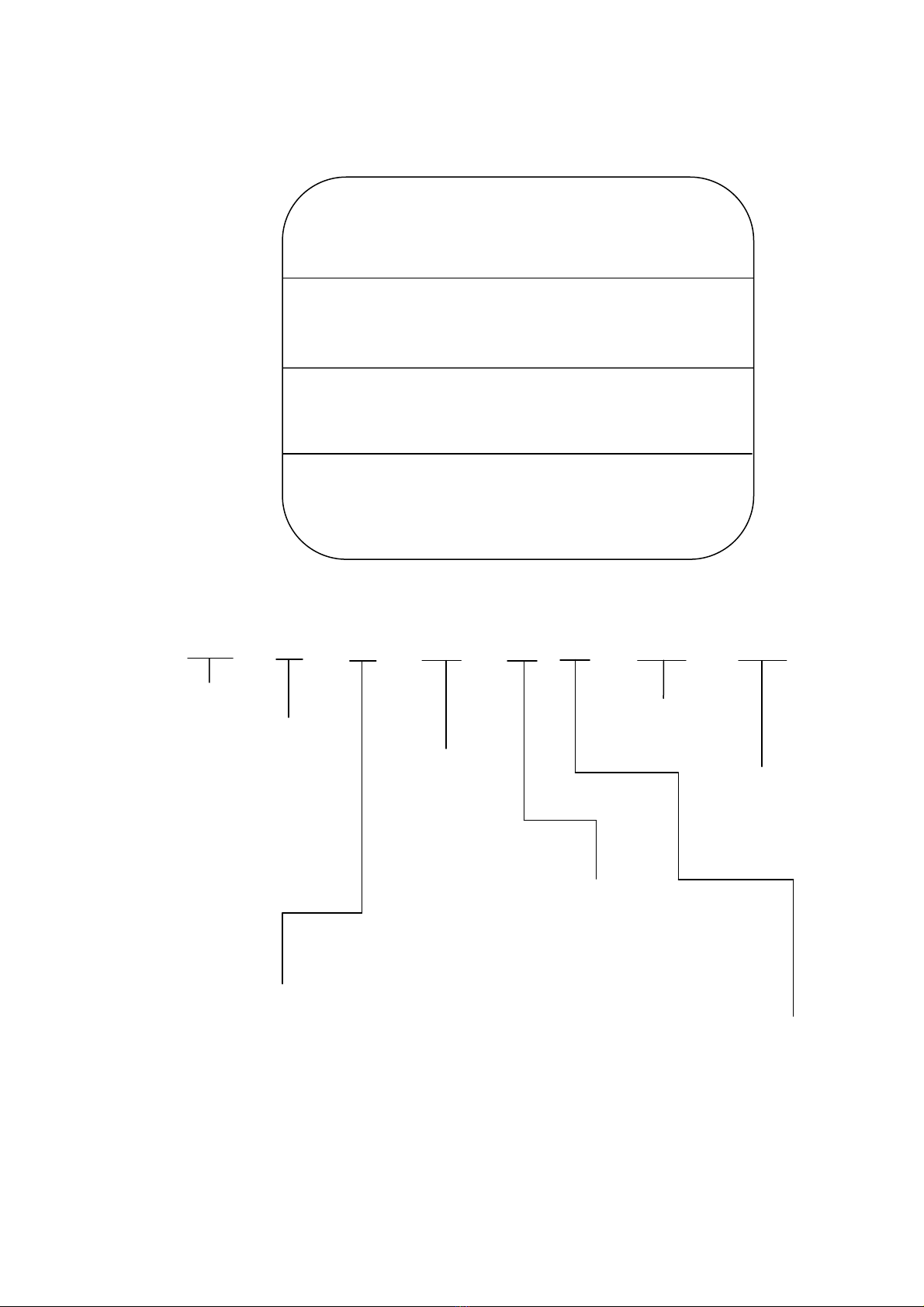
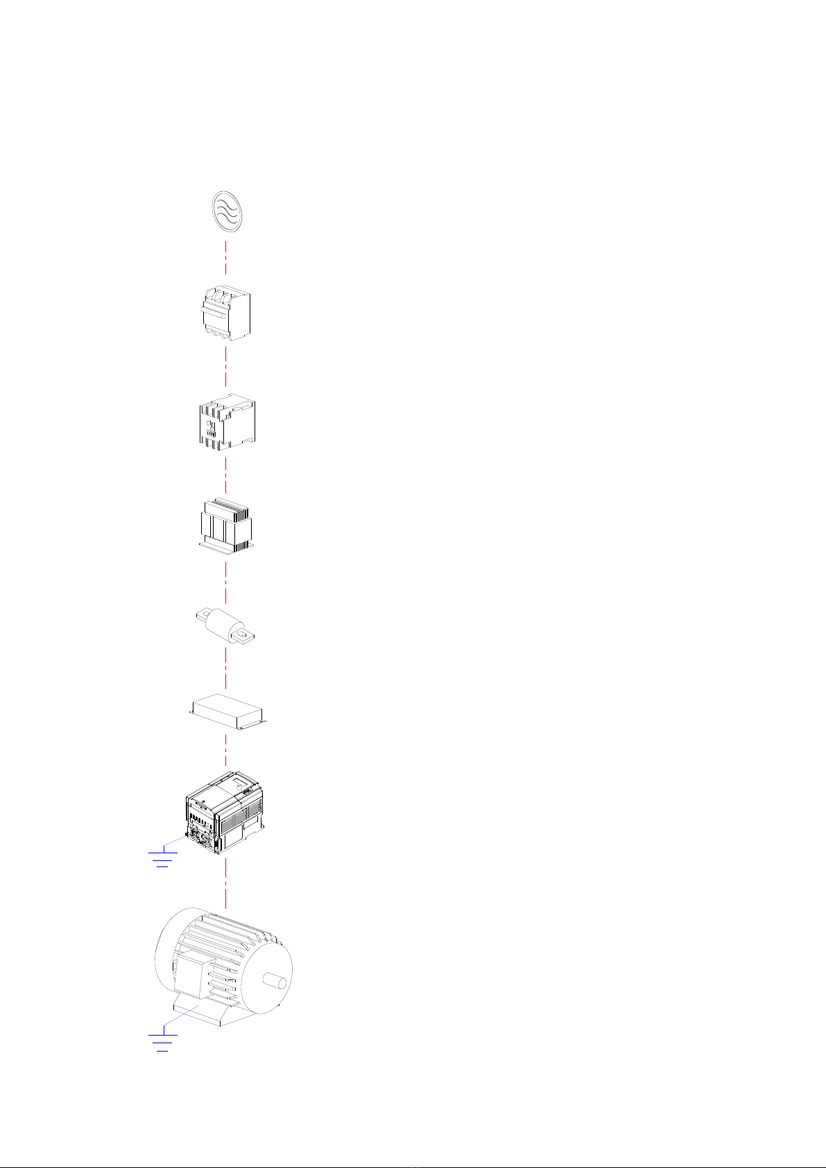
Power
Molded-case
circuit breaker
Magnetic
contactor
C reactor for
power
improvement
Install fast
action fuse
(If necessary)
Input noise
filter
CVP inverter
Ground
Three-phase
cage motor
Ground