manuals.online logo
Brands
  1. Home
  2. •
  3. Brands
  4. •
  5. TECO
  6. •
  7. Inverter
  8. •
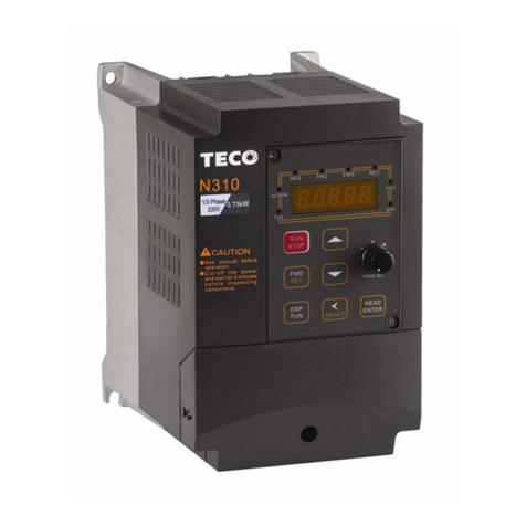
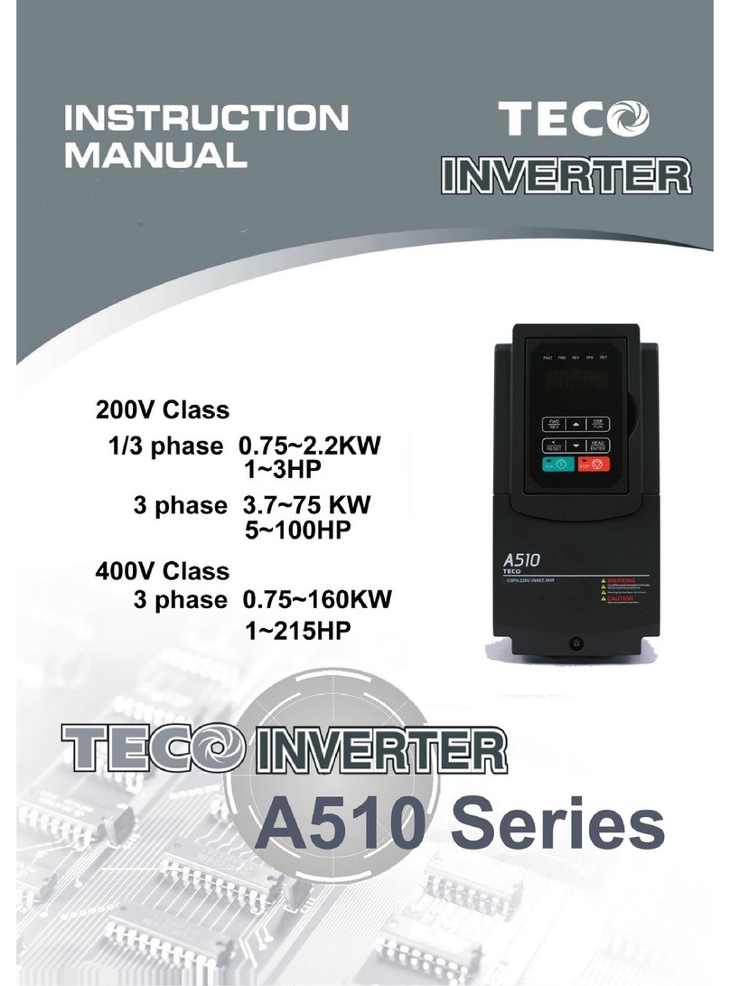
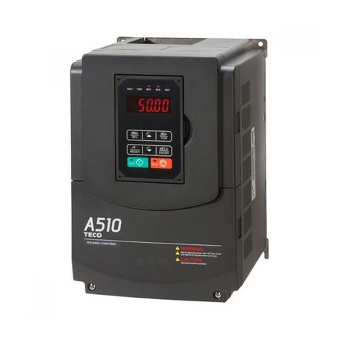
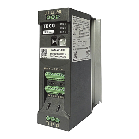
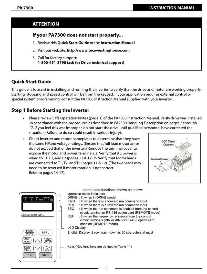
  9. TECO T-verter N2 Series User manual

TECO T-verter N2 Series User manual

N2-220V
N2-440V
0.4~22KW
(1.2~33.2KVA)
0.75~22KW
(1.7~36.6KVA)
Adjustable Frequency
A.C. Motor Drive
N2 Series
Operations Manual
Table of Contents
Foreword.................................................................................................. 1
Precautions for Operation........................................................................ 2
Operational Environment......................................................................... 6
General Introduction ................................................................................ 7
Specifications........................................................................................... 9
Wiring Rules........................................................................................... 11
Keypad Operations................................................................................ 21
Parameter List........................................................................................ 22
Functional Description ........................................................................... 30
Failure Codes......................................................................................... 60
Maintenance Section ............................................................................. 65
Filters..................................................................................................... 66
Dimensions............................................................................................ 70
Braking Resisters & Reactors................................................................ 74
Trouble Shooting.................................................................................... 78
This manual may be modified when necessary because of improvement of the product,
modification, or changes in specifications. This manual is subject to change without notice.
4KA72X026T01 Ver:06 2005.09
Distributor
7th., 49, Wu Kong 6Rd. Wu-Ku
Industrial Park, Taipei County 248,
Taiwan
1
Foreword
To fully employ all functions of this T-verter and to ensure the safety for its users, please read
through this operations manual in detail. Should you have any further questions, please feel free to
contact your local distributor or regional representative.
PLEASE READ AND UNDERSTAND THIS MANUAL BEFORE
OPERATING THIS T-VERTER
The T-verter is a power electronic device. For safety reasons, please read carefully those
paragraphs with “WARNING” or “CAUTION” symbols. They are important safety precautions to be
aware of while transporting, installation, operating or examining the T-verter. Please follow these
precautions to ensure your safety.
WARNING Personnel injury may be resulted by improper operation.
CAUTION The T-verter or mechanical system may be damaged by improper operation.
WARNING
zDo not touch the PCB or components on the PCB right after turning off the power before the
charging indicator went off.
zDo not attempt to wire circuitry while power is on. Do not attempt to examine the components
and signals on the PCB while T-verter operating.
zDo not attempt to disassemble or modify internal circuitry, wiring, or components of the
T-verter.
zThe grounding terminal of the T-verter must be grounded properly (200V class: Ground to 100
Ωor less, 400V class: Ground to 10Ωor less).
zThis is a product of the restricted sales distribution class according to EN61800-3.
In a domestic environment this product may cause radio interference in which case the user
may be required to take adequate measures.
CAUTION
zDo not attempt to perform dielectric strength test to internal components of the T-verter. There
are sensitive semiconductor-devices vulnerable to high voltage in the T-verter.
zDo not connect the output terminals: T1 (U), T2 (V), and T3 (W) to AC power input
zThe CMOS IC on the primary PCB of the T-verter is vulnerable to static electrical charges. Do
not contact the primary PCB of the T-verter.
2
Precautions for operation
Examination before installation
Every T-verter has been fully tested and examined before shipment. Please carry out the following
examination procedures after unpacking your T-verter.
zCheck to see if the model number of the T-verter matches the model number of the T-verter
that you ordered.
zCheck to see whether any damage occurred to the T-verter during shipment. Do not connect
the T-verter to the power supply if there is any sign of damage.
Before turning ON power
CAUTION
Choose the appropriate power source with correct voltage settings for the input voltage
specification of the T-verter.
WARNING
Special care must be taken while wiring the primary circuitry terminals. The (L1) (L2)
and (L3) terminals must be connected to the input power source and must not be
mistakenly connected to (T1) (T2) or (T3) output terminals. This may damage the
T-verter when the power is turned on.
CAUTION
zDo not attempt to transport the T-verter by the front of the cover. Securely hold the
T-verter by the heat-sink mounting chassis to prevent the T-verter from falling, this
may cause personnel injury or damage to the T-verter itself.
zInstall the T-verter onto a firm metal base plate or another non-flammable type
material. Do not install the T-verter onto or nearby any flammable material.
zAn additional cooling fan may need to be installed if several T-verters are installed
into one control panel. The inside temperature inside an enclosed panel should be
below 40 degrees to avoid overheating.
zTurn off the power supply before proceeding to remove or perform any work on any
panel. Carry out installation procedures according to instructions given in order to
avoid a situation resulting in an operational malfunction.
zThis product is not provided with over speed protection.
zOnly intended for use in a pollution degree 2 macro environment or equivalent
3
When power is applied
WARNING
Do not attempt to install or remove input or out put connectors of T-verter when the
power supply is turned on. Otherwise, the T-verter may be damaged due to the surge
peak caused by the insertion or removal.
Under Operation
WARNING
zDo not use a separate device to switch ON or OFF motor during operation.
Otherwise, the T-verter may experience an over-current breakdown.
zWhen momentary power loss is longer than 2 seconds (the large of horse power,
the longer of time), the inverter does not have enough storage power to control the
circuit; Therefore, when power is regenerated, the operation of the inverter is
based on the setup of Fn_10/16 and the condition of external switch, this is
considered to be「restart」in the following paragraphs.
zWhen the momentary power loss is short, the inverter still has enough storage
power to control the circuit; therefore, when power is regenerated, the inverter will
automatically start operation again depends on the setup of Fn_31/32.
zWhen restart the inverter, the operation of the inverter is based on the setup of
Fn_10 and the condition of external switch (FWD/REV button). Attention: the
restart operation is irrelevant with Fn_31/32/34/35.
(1) When Fn_10=0, the inverter will not start after restart.
(2) When Fn_10=1 and the external switch (FWD/REV button) is OFF, the
inverter will not start after restart.
(3) When Fn_10=1, the external switch (FWD/REV button) is ON, and
Fn16=XXX0, the inverter will start automatically after restart. Attention: Base
on safety reason, please turn off the external switch (FWD/REV button) after
power loss to avoid possible damage to the machine and the human body
after sudden regeneration of power.
WARNING
zDo not remove the front cover of the T-verter when the power is ON to avoid
personnel injury caused by electrical shock.
zWhen the automatic restart function is enabled, the motor and machinery will be
restarted automatically.
4
CAUTION
zDo not touch the heat-sink base during operation.
zThe T-verter can be easily operated from a low-speed to high-speed range. Please
reconfirm the operating range of motor and the machinery you are controlling.
zDo not examining the signals on the PCB of the T-verter when it is under operation.
zAll T-verters are properly adjusted and set before delivery.
CAUTION
Do not proceed with disassemble or examination procedure before ensuring that the
power is off and the Power LED extinguished.
When performing an examination or maintenance
CAUTION
The environment temperature should be within –10OC ~ +40OC and humidity under
95% RH without condensing. Besides, the T-verter should be free from water dripping
or metal dust.
Others
WARNING
Never modify the product.
Failure to observe this warning can result in an electrical shock or personal injury and
will invalidate the guarantee.
.
5
Taking Precautions:
Avoid any direct sunlight Keep away from
corrosive gas or liquid Keep away from oil
grease and gas
Keep away from salty
environments
Keep away from rain or
where dripping water may
get into the T-verter
Avoid metal dust and
dusty environments
Avoid massive vibration
Avoid excessive direct heat
Avoid where
environmental
temperatures are too high
K
eep away
f
rom
hi
g
h
electrical-magnetic waves
or ultra-high waves. Keep away from
radioactive matter Keep away from
flammable material
oil
6
Operational Environment
The installation site of the T-verter is very important. It relates directly to the functionality and the life
span of your T-verter. Please carefully choose the installation site to meet the following
requirements:
zMount the unit vertically
zEnvironment temperature: -10OC ~ +40OC(with cover removed: -10OC ~ +50OC)
zAvoid placing close to any heating equipment
zAvoid water dripping or humid environment
zAvoid direct sunlight
zAvoid oil or salty corrosive gas
zAvoid contacting corrosive liquid or gas
zPrevent foreign dusts, flocks, or metal scraps from entering interior
zAvoid electric-magnetic interference (soldering or power machinery)
zAvoid vibration, if vibration cannot be avoided, an anti-rattle mounting device should be
installed to reduce vibration.
zIf the T-verter is installed in an enclosed control panel, please add additional cooling using an
external fan. This will allow additional airflow and cooling.
zPlacement of external fans should be directly over the top of the T-verter.
zFor proper Installation of the T-verter you must place the front side of the T-verter facing front
and the top of the T-verter in the up direction for better heat dissipation.
zInstallation must be compliant to the following requirements.
Ventilation-10OC ~ +40OC
& Installation Direction
Front & Side Views
T-verter
7
General Introduction:
General
T-verter N2 series is a high performance general-purpose inverter that incorporates a high efficiency
Pulse Width Modulated (PWM) design and advanced IGBT technology. The output closely
approximates a sinusoidal current waveform to allow variable speed control of any conventional
squirrel cage induction motor.
Receiving
This unit has been put through demanding tests at the factory prior to shipment.
Before unpacking please check the following:
1. Identify the description of the product found on the label with your purchase order.
2. Inspect for transport damage (serious damage of carton may lead to damage of the unit)
Please check the followings after unpacking:
a. Check if the specifications (current & voltage) on the front cover match to your application
requirement.
b. Check all the electrical connections and screws.
c. Verify that there is no visible damage to any of the components.
If any part of the T-verter or the box it came in is damaged, please notify the carrier and your
distributor immediately.
8
Installation:
Location
Picking the proper installation location for the T-verter is imperative in order to achieve the
maximum specified performance & operation from the Drive. The T-verter should always be
installed in areas where the following conditions exist.
* Good ambient operating temperature:
-10 to 40 ℃(14 to 104 F), -10 to 50 ℃(14 to 122 F) with cover removed
* IP Rating: IP 20 for all models. If the T-verter is placed in another enclosure, please provide
addition cooling using an external fan.
* Protected from rain & moisture.
* Shielded from direct sunshine.
* Free from metallic particles and corrosive gas.
* Free from excessive vibration. (Below 0.5G)
Positioning
For effective ventilation and maintenance purposes, sufficient clearance (as shown in figure 2.1)
around the T-verter is necessary. The T-verter must be installed with heat sink ribs oriented
vertically.
zAllow 12cm clearance on both
sides of the enclosure
zBe sure to allow the air to move
freely through the heat sink
area.
=2/7

)< 1 $03
9
Basic Specification:
Mode No. Identification
N2 - 2 01 H 3 N4
Series Input Voltage Capacity Specification Phase of input power Enclosure
2 : 200V Class P5 : 0.5Hp M : Standard type Blank : 1/3 phase Blank : IP20
4 : 400V Class ~ H : Advanced type 3 : 3 phase N4 : IP65(NEMA4)
30 : 30Hp
1/ 3 Phase 200-240 Volts
N2-□□□—xxx *1 2P5 201 202 203 205 208 210 215 220 230
Horse Power 1/2 1 2 3 5 7.5 10 15 20 30
Rated Motor KW 0.4 0.75 1.5 2.2 3.7 5.5 7.5 11 15 22
Rated Current (A) 3.1 4.5 7.5 10.5 17.5 26 35 49 64 87
Output (KVA) 1.2 1.7 2.9 4.0 6.7 9.9 13.3 18.7 24.4 33.2
Input Voltage Max. (1 / 3 Phase) (200~240 Volts +-10%) (50/60Hz +-5%) (5 h.p. & above 3 Phase Only)
Output Voltage Max. 3 Phase 200 ~ 240 (proportional to input voltage)
IP20 Weight (Kg) 1.4 1.4 2.5 4.0 4.0 6.8 7.1 12.3 12.5 13.8
Power Loss
Ride Through (s) 1 1 2 2 2 2 2 2 2 2
3 Phase 380 ~ 480 Volts
N2-□□□-xxx *1 401 402 403 405 408 410 415 420 430
Horse Power 1 2 3 5 7.5 10 15 20 30
Rated Motor KW 0.75 1.5 2.2 3.7 5.5 7.5 11 15 22
Rated Current (A) 2.3 3.8 5.2 8.8 13 17.5 25 32 48
Output (KVA) 1.7 2.9 4.0 6.7 9.9 13.3 19.1 24.4 36.6
Input Voltage Max. ( 3 Phase 380 ~ 480 Volts +- 10%) (50/60Hz +- 5%)
Output Voltage Max. 3 Phase 380 ~ 480 Volts (proportional to input voltage)
IP20 Weight (Kg) 2.4 2.5 3.8 4.0 7.0 7.3 12.3 12.5 13.5
Power Loss
Ride Through (s) 1 1 2 2 2 2 2 2 2
Note *1 (IP65) NEMA4 enclosure type only available for 0.5 ~ 10HP & below
10
Functional Specification:
Carrier frequency 1 - 12 K
Frequency Control Range 0.1 – 400 Hz
Frequency Accuracy Digital: 0.01% (-10 ~ 40 °C); Analog: 0.4% (25+-10 °C)
Frequency Resolution 0.01 Hz with computer or PLC control, 0.1 Hz with keypad control when freq.
above 100 Hz
Frequency Setting Signal (0-5VDC) (0-10VDC) (4-20mA) (0-20mA)
Accel / Decel Time 0.1-3600 SEC with (2) S-curves
Braking Torque About 20% (built-in Braking transistor)
Control
Characteristics
V/F Pattern 18 patterns, one curve programmable
Instantaneous Over Current Approx. 200% rated current
Overload T-verter: 150% / 1 minute
Motor Overload Protection Electronic thermal overload relay
Over voltage 200V series: (DC bus voltage exceeds 427V)
400v series: (DC bus voltage exceeds 854V)
Under voltage 200V series: (DC bus voltage drops < 200V)
400v series: (DC bus voltage drops < 400V)
Momentary Power Loss 0~2 seconds: The T-verter can be restarted using the speed search feature
Heat Sink Fin Overheat Protected by thermister
Protection
Function
Ground Fault Electronic circuit protection
Operation signals Forward/Reverse operation, by keypad or hardwire contact, multiple individual
commands
Reset Released protection while the protective function is operating
Input
Signal Multifunction Input Refer to function illustration in Fn_56
Multifunction Output Refer to function illustration in Fn_61Output
Signal Fault output 250VAC 1A, 30VDC 1A or less
Built-in Function
Frequency reference bias/gain; up/lower limit; manual torque boost; frequency
meter calibrating gain; auto restart attempt; skip frequency; S-curve
ACCEL/DECEL; Carrier frequency adjust.(1-12KHz)
Communication link function
Digital operator monitor Frequency command, output frequency, speed, output current, output voltage,
P-N bus voltage, rotating direction
Operation
Conditions
Analog Output Monitor Analog output (0-10V), possible to select output frequency & setting freq. &
output voltage & P-N bus voltage
Location Indoor (protected from corrosive gas and dust)
Ambient Temperature -10 degrees ~ 40 degrees © 50 degrees with cover removed
Humidity 0-95%(non condensing)
Environ
mental
Vibration 0.5G
Enclosure IP20 / IP65 (NEMA4)
EMC EN50081-1, EN50082-2 (with optional filter)
LVD EN50178
UL UL 508C
zN2-205 and above capacity are not CE complied
11
Wiring Rules:
1. Notice for wiring
A. Screwdrivertorque: Connect cables with a screwdriveror other tools and follow the torque listed
below.
Securing torque
Horsepower Power source Max. Nominal torque for TM1 terminal
0.5/1/2/3 200 – 240V
1/2 380 – 480V 1.33 lbs.-ft 16 lbs.-in
5/7.5/10 200 –240V
3/5/7.5/10 380 –480V 1.15 lbs.-ft 13.8 lbs.-in
15/20/25/30 200 –240V
15/20/25/30 380 –480V 1.83 lbs.-ft 22 lbs.-in
B. Power wires
Power wires are wires connected to L1, L2, L3, T1, T2, T3, P and R. Choose wires in
accordance with the following criteria:
(1) Use wires with copper cores only.Decide diameters of wires based on working conditions at
105oC.
(2) For nominal voltage of wires, the minimum voltage of 240VAC type is 300V, and 480VAC
type is 600V.
C. Control wire
Control wire is connected to TM2 control terminal. Choose the wire in accordance with the
following criteria:
(1) Use wires with copper cores only. Decide the diameter of the wire based on working
conditions at 105℃.
(2) For nominal voltage of wires, the minimum voltage of 240VAC type is 300V, and 480VAC
type is 600V.
(3) To avoid noise interference, do not route the control wire in the same conduit with power
wires and motor wires.
D. Nominal electrical specifications of the terminal base: The following are nominal values of TM1:
12
Horsepower Power source Max. Volts Amps
0.5/1/2/3 200 – 240V
1/2 380 – 480V 300 20
5/7.5/10 200 –240V
3/5/7.5/10 380 –480V 600 40
15/20 200 –240V
15/20/25/30 380 –480V 600 60
25/30 200 –240V 600 100
Note: Nominal values of input and output signals (TM2) – follow the specifications of class 2
wiring.
2. Fuse types
To protect the inverter most effectively, use fuses with current-restraint function.
Horsepower Power source Max. Rated fuse specifications
2 15A, 600VAC, 100KA, I.R.
3 20A, 600VAC, 100KA, I.R.
5 30A, 600VAC, 100KA, I.R.
7.5/10 60A, 600VAC, 100KA, I.R.
15/20 100A, 600VAC, 100KA, I.R.
25/30
200 – 240V
150A, 600VAC, 100KA, I.R.
1 5A, 600VAC, 100KA, I.R.
2 10A, 600VAC, 100KA, I.R.
3 15A, 600VAC, 100KA, I.R.
5 20A, 600VAC, 100KA, I.R.
7.5/10 40A, 600VAC, 100KA, I.R.
15/20 70A, 600VAC, 100KA, I.R.
25/30
380 – 480V
100A, 600VAC, 100KA, I.R.
13
3. Use the circuit properly, and the carrying current does not exceed 5000 Arms.
The maximum output voltage is 240V for 200 – 240V models when carrying
current is below 5000 Arms.
4. We cannot guarantee safety for over-speed or similar situations. Do not connect
the inverter to a controller or similar devices with current restraint function.
5. Notice:
5.1 To avoid shock hazard, do not touch any electrical component when the power is applied or
just after the power plug is unplugged.
5.2 Do not perform wiring on the inverter while it is still electrified. Disregard of this notice can
cause serious injure or death to persons.
6. This product is designed to be used under class 2 contaminated environment or
similar environments.
14
■Applicable magnetic contactor and wires
Molded-case circuit breaker/magnetic contactor
zOur bears no responsibilty to service for failures caused by the following conditions:
(1) A molded-case circuit breaker is not installed, or an improper or overrated breaker is
used, between the power source and the inverter.
(2) A magnetic contactor, a phase capacitor, or a burst absorber is connected between the
inverter and the motor.
Inverter
model N2-2P5 N2-201 N2-202 N2-203 N2-205 N2-208 N2-210 N2-215
N2-220 N2-230
MCCB made
by Teco TO-50E
20A TO-50E
20A TO-50E
30A TO-50E
30A TO-50E
30A TO-50E
50A TO-100S
60A TO-100S
100A TO-225S
175A
MC made by
Teco CN-11 CN-16 CN-18 CN-25 CN-50 CN-65 CN-100 CN-100
Main circuit
terminals
(TM1)
Wire gauge
2.0 mm2
Terminal screw
M4
Wire gauge
3.5 mm2
Terminal screw
M6
Wire gauge
5.5 mm2
Terminal screw
M6
Wire
gauge
14 mm2
Terminal
screw
M8
Wire
gauge
22 mm2
Terminal
screw
M8
Signal
terminals
(TM2) Wire gauge 0.75mm2 (# 18 AWG), terminal screw M3
Inverter
model N2-401/402/403/405 N2-408 N2-410 N2-415 N2-420 N2-430
MCCB made
by Teco TO-50E
15A TO-50E
20A TO-50E
30A TO-50E
50A TO-100S
60A TO-100S
100A
MC made by
Teco CN-11 CN-16 CN-18 CN-25 CN-35 CN-50
Main circuit
terminals
(TM1) Wire gauge 2.0mm2
Terminal screw M4 Wire gauge 3.5mm2
Terminal screw M4
Wire
gauge
5.5mm2
Terminal
screw
M6
Wire
gauge
8mm2
Terminal
screw
M6
Wire
gauge
14mm2
Terminal
screw
M6
Signal
terminals
(TM2) Wire gauge 0.75mm2 (# 18 AWG), terminal screw M3
zUse three-phase cage reaction motor with capacity suitable for the inverter.
zWhen one inverter is used to drive several motors, the total current of all motors running
simultaneouly must be less than the capacity of the inverter, and each motor has to be
equipped with a proper thermal relay.
zDo not add capacitive component, such as a phase capacitor, LC, or RC, between the inverter
and the motor.
15
▓Precautions for peripheral applications:
Power source:
zMake sure the voltage applied is correct to avoid damaging
the inverter.
zA molded-case circuit breaker must be installed between
the AC source and the inverter.
Molded-case circuit breaker:
zUse a molded-case circuit breaker that conforms to the
rated voltage and current of the inverter to control the
power ON/OFF and protect the inverter.
zDo not use the inverter as the switch for run/stop switching.
Leakage breaker:
zInstall a leakage breaker to prevent error operation caused
by electric leakage and to protect operators.
Magnetic contactor:
zNormal operations do not need a magnetic contactor. But a
contactor has to be installed when performing functions
such as external control and auto restart after power
failure, or when using brake controller.
zDo not use the magnetic contactor as the run/stop switch
of the inverter.
Reactor for power improvement:
zWhen inverters below 200V/400V 15KW are supplied with
high capacity (above 600KVA) power source, a reactor
can be connected to improve the power performance.
Input noise filter:
zA filter must be installed when there are inductive load
around the inverter.
Inverter:
zInput power terminals L1, L2, and L3 can be used in any
sequence regardless of phases.
zOutput terminals T1, T2, and T3 are connected to U, V,
and W terminals of the motor. If the motor is reversed while
the inverter is forward, just swap any two terminals of T1,
T2, and T3.
zTo avoid damaging the inverter, do not connect the input
terminals T1, T2, and T3 to AC power.
Connect the ground terminal properly. 200V class: Ground
to 100Ωor less, 400V class: Ground to 10Ωor less.
Power
Molded-case
Magnetic
contactor
AC reactor
for power
Input noise
filter
Ground
Three-phase
cage motor
N
2 inverte
r
Ground
16
Make external connections according to the following instruction. Check connections after
wiring to make sure all connections are correct. (Do not use the control circuit buzzer to
check connections)
(A) Main circuit’s wiring must separate from other high voltage or high current power line to
avoid noise interference. See figures below.
zThe inverter uses dedicated power line
z
A
dd a noise filter or separation transformer
when the inverter shares the power line
with other machines.
zA general noise filter may not provide
rightful results
zA noise filter in the output of the main circuit can suppress conductive noise. To prevent
radiative noise, the wires should be put in a metal pipe and distance from signal lines of other
control machines for more than 30 cm.
電源
V2
Power source
Power source
N
2
N
2
Machine
Machine
General
noise
filter General
noise
filter
Separation transformer
General
noise
filter
N
2
N2
General
noise
filte
r
Power source
Control machine
More than 30 cm
General
noise
filter
Machine Machine
17
When the connection between the inverter and the motor is too long, consider the voltage drop of the
circuit. Phase-to-phase voltage drop (V) =
3 ×resistance of wire (Ω/km)×length of line (m)×current×10-3. And the number of carriers must be
adjusted based on the length of the line.
The length of the line between the inverter and
the motor Less than 50m Less than 100m More than 100m
Number of carriers allowed Below 12KHz Below 10KHz Below 5KHz
Settings of Fn_43 parameter 15 12 9
(B) The wiring of the control circuit must be separated and routed away from the main circuit control
line or other high voltage or current power lines to avoid noise interference.
zTo avoid error actions caused by noise interference, shield the control circuit wiring with a
twisted wire, and connect the sheilding wire to a ground terminal. See the figure below.
The wiring distance should not exceed 50 m.
(C) Ground the ground terminal of the inverter properly. 200V class: Ground to 100Ωor less, 400V class:
Ground to 10Ωor less.
zGround wiring is based on the electrical equipment technical basis (AWG) and should be made
as short as possible.
zDo not share the ground of the inverter to other high current loads (welding machine, high
power motor). Connect the terminal to its sole ground.
zDo not make a loop when several inverters share a common ground point.
(a) Good (b) Good (c) Bad
(D) To ensure maximum safety,use proper wire gauges for the main power circuit and control circuit
according to relative regulations.
(E) After wiring, check that the wiring is correct, wires are intact, and terminal screws are secured.
Shielding wires Protective
To ground terminal
(See instructions of filter
wiring)
Wrapped with insulating tape
Do not connect this en
d

This manual suits for next models

2

Other TECO Inverter manuals

TECO L510 User manual

TECO

TECO L510 User manual

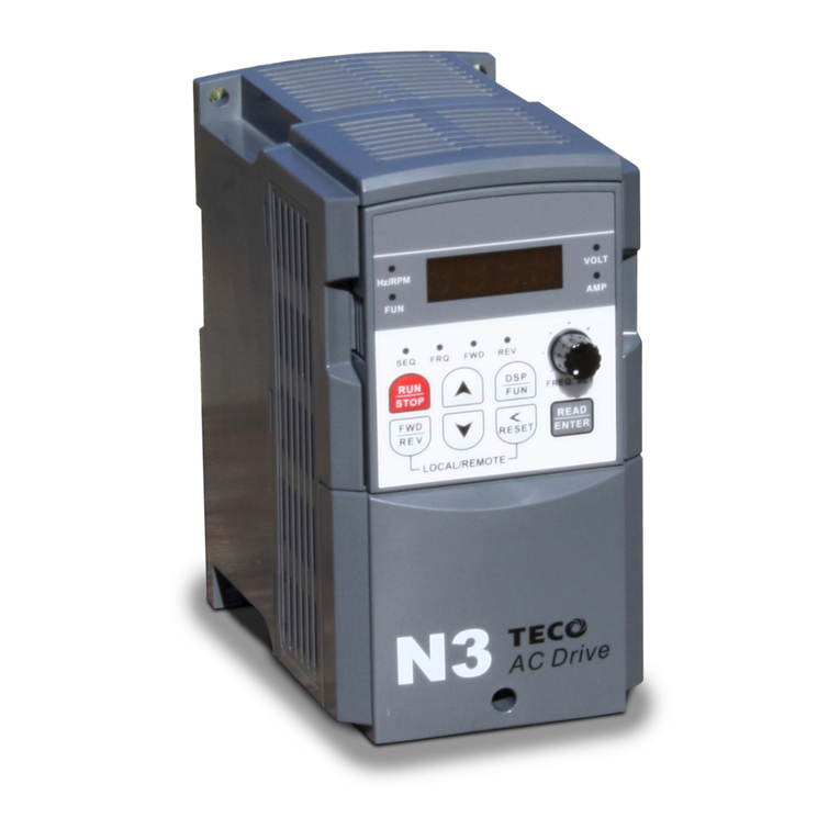
TECO N3 Series User manual

TECO

TECO N3 Series User manual

TECO N310 Series User manual

TECO

TECO N310 Series User manual

TECO MV510 Series User manual

TECO

TECO MV510 Series User manual

TECO E510s Series User manual

TECO

TECO E510s Series User manual

TECO L510 User manual

TECO

TECO L510 User manual

TECO FM50 Series Guide

TECO

TECO FM50 Series Guide

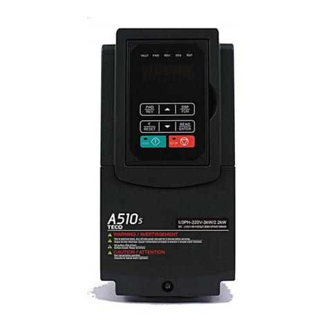
TECO A510 Installation and operating manual

TECO

TECO A510 Installation and operating manual

TECO A510 User manual

TECO

TECO A510 User manual

TECO L510-1P2-H1-N User manual

TECO

TECO L510-1P2-H1-N User manual

TECO L510S Series User manual

TECO

TECO L510S Series User manual

TECO A510-2001-H User manual

TECO

TECO A510-2001-H User manual

TECO A510-2001-H User manual

TECO

TECO A510-2001-H User manual

TECO e510 series User manual

TECO

TECO e510 series User manual

TECO SPEECON 7200GS User manual

TECO

TECO SPEECON 7200GS User manual

TECO A510s User manual

TECO

TECO A510s User manual

TECO F510 series User instructions

TECO

TECO F510 series User instructions

TECO e510 series User manual

TECO

TECO e510 series User manual

TECO F33 Series User manual

TECO

TECO F33 Series User manual

TECO JN5-CM-USB User manual

TECO

TECO JN5-CM-USB User manual

TECO e510 series User manual

TECO

TECO e510 series User manual

TECO A510s Manual

TECO

TECO A510s Manual

TECO L510S Series User manual

TECO

TECO L510S Series User manual

TECO A510s User manual

TECO

TECO A510s User manual

Popular Inverter manuals by other brands

Omron RX -  1 System configuration

Omron

Omron RX - 1 System configuration

Asian Electron PIC2KVA Series instruction manual

Asian Electron

Asian Electron PIC2KVA Series instruction manual

Delta Electronics AC Drive VFD-F Series user manual

Delta Electronics

Delta Electronics AC Drive VFD-F Series user manual

Generac Power Systems PV Link installation manual

Generac Power Systems

Generac Power Systems PV Link installation manual

Giandel PS-1200JCR user manual

Giandel

Giandel PS-1200JCR user manual

Grape Solar GS-600-KIT-BT-INV Quick connect guide

Grape Solar

Grape Solar GS-600-KIT-BT-INV Quick connect guide

Cotek SK700-112 user manual

Cotek

Cotek SK700-112 user manual

Tronix Tronix Explorer XT user guide

Tronix

Tronix Tronix Explorer XT user guide

SMA SUNNY TRIPOWER CORE1 Replacement manual

SMA

SMA SUNNY TRIPOWER CORE1 Replacement manual

YOKOGAWA FG410 user manual

YOKOGAWA

YOKOGAWA FG410 user manual

Clarke Arc/Tig85 Operating & maintenance instructions

Clarke

Clarke Arc/Tig85 Operating & maintenance instructions

RedEarth HoneyBadger installation manual

RedEarth

RedEarth HoneyBadger installation manual

Growatt MIC 1000TL-X Installation & operation manual

Growatt

Growatt MIC 1000TL-X Installation & operation manual

Prudent Way PWI-IV80-SB user manual

Prudent Way

Prudent Way PWI-IV80-SB user manual

Afore BNT003KTL Installation and operation manual

Afore

Afore BNT003KTL Installation and operation manual

Champion CPG4000DHY-EU Operator's manual

Champion

Champion CPG4000DHY-EU Operator's manual

Weidmüller PV DC COMBINER BOX operating instructions

Weidmüller

Weidmüller PV DC COMBINER BOX operating instructions

Mitsubishi Electric FR-A7NC E kit-SC instruction manual

Mitsubishi Electric

Mitsubishi Electric FR-A7NC E kit-SC instruction manual

manuals.online logo
manuals.online logoBrands
  • About & Mission
  • Contact us
  • Privacy Policy
  • Terms and Conditions

Copyright 2025 Manuals.Online. All Rights Reserved.