manuals.online logo
Brands
  1. Home
  2. •
  3. Brands
  4. •
  5. Teknion
  6. •
  7. Indoor Furnishing
  8. •
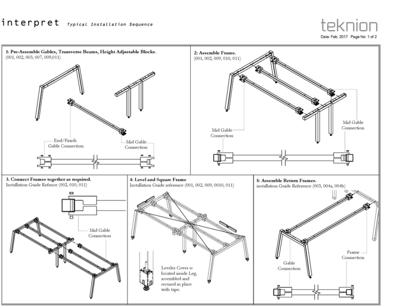
  9. Teknion Interpret WWSSB Operating and maintenance instructions

Teknion Interpret WWSSB Operating and maintenance instructions

Part and Product Identification
Section:
Description: Page No:
Date:
Rev. No: 4
Feb 2017 1 of 22
INT_010
interpret
AA1
AQ1
AM1
AB1
Wire Gap Worksurface
(WWWRW) x1 per Frame
NOTE: For Access Door
installation refer to INT_404
For Customer Support please contact
[email protected]
NOTE: Quatities of Worksurface
Support Brackets (E5) vary:
Frame 48"-54" - x2
Frame 60"-96" - x4
Straight Leg Frame shown
Angled Legs Parts are listed on pg. 4
AC1
AI1
AJ1
AH1
AR1-Drilling Template
(A16-1623) x1
AF1
AG1
AE1
AA1-End Leg, Straight
Single Sided
(N02-3698) x1
AC1-Transverse Beam
Assembly
(N02-3688) x1
AD1-1/4-20x3-1/2 Flat
Head Machine Quad
(E01-0771) x2
AE1-Front Standoff
(B02-0658) x1
or x2
AF1-Single Sided Rail
Assembly
(N02-2150) x1
AH1- End Modesty,
Single Sided
(C05-7225) x1
AQ1-Gable Corner Bracket
(N09-4200) x1
AI1-Infill Bottom Bracket
(A16-0947) x2
AK1-1/4-20 UNC x0.500" 2A,
Cross Square Socket
Truss Head, Machine
Steel, Zinc
(E01-0110) x6
or x10
AN1-#10x0.875 Quad Pan
Washer
(E07-0077) x6
or x12
AL1-#8118x1/2 Cross Square
Comb, Self tap
(E07-0012) x2
AM1-Worksurface Support
Bracket
(N09-4134) x2
or x4
AG1-Single Sided Rail Cap
(N02-2151) x1
AJ1-Infill Bottom Bracket
Cover
(A25-0389) x2
AP1-5/16-18 Hex Jam Nut
.190 Thick Zinc,
(HN03118JZ)
(E03-0551) x4 or x8
AO1-5/16-18x3/8 Button
Head, Hex Socket
(E01-0798) x4
or x8
AC2-5/16-18x2.5 Socket
Head Screw
(E01-0756) x8
AC3-5/16-18 Hex Nut
1/2 A/F .265 Thick
(E01-0755) x8
AB1 -Mid Leg, Str.
Single Sided
(N02-3699) x1
AQ - (X05-0273) x2
AQ2-5/16-18 HexNut
(E03-0551) x1
AQ3-5/16-18x3/8 Hex
Socket
(E01-0798) x1
AQ4-1/4-20 UNC x0.500"
2A, Cross Square
(E01-0110) x1
Single Sided Beginning Frame (WWSSB),
Power Cut - out Worksurface (WWWRP)
Leveler Cover is
located inside Leg,
assembled and
secured in place
with tape.
Part and Product Identification
Section:
Description: Page No:
Date:
Rev. No: 4
Feb 2017 2 of 22
INT_010
interpret
BK1
NOTE: Quatities of Worksurface
Support Brackets (I6) vary:
Frame 48"-54" - x2
Frame 60"-96" - x4
Straight Leg Frame shown
Angled Legs Parts are listed on pg. 4
BB1
BD1
BA1
BE1
BF1
BO1
BG1
BH1
BC1-1/4-20x3-1/2 Flat
Head Machine
Quad
(E01-0771) x2
BD1-Front Standoff
(B02-0658) x1
or x2
BE1-Single Sided Rail
Assembly
(N02-2150) x1
BF1- End Modesty,
Single Sided
(C05-7226) x1
BG1-Infill Bottom
Bracket
(A16-0947) x2
BL1-#10x0.875 Quad Pan
Washer
(E07-0077) x 6
or x12
BJ1-#8118x1/2 Cross
Square Comb, Self Tap
(E07-0012) x2
BK1-Worksurface Support
Bracket
(N09-4134) x2
or x4
BH1-Infill Bottom
Bracket Cover
(A25-0389) x2
BN1-5/16-18 Hex Jam Nut
.190 Thick Zinc,
(HN03118JZ)
(E03-0551) x4 or x8
BM1-5/16-18x3/8 Button
Head, Hex Socket
(E01-0798) x4
or x8
BP1-Drilling Template
(A16-1623) x1
BB2-5/16-18x2.5 Socket
Head Screw
(E01-0756) x8
BB3-5/16-18 Hex Nut
1/2 A/F .265 Thick
(E01-0755) x8
BA1-Mid Leg, Straight
Single Sided
(N02-3699) x1
BI1-1/4-20 UNC x0.500"
2A, Cross Square Socket
Truss Head, Machine
Steel, Zinc
(E01-0110) x6
or x10
BO1-Gable Corner
Bracket
(N09-4200) x1
BO - (X05-0273) x2
BO2-5/16-18 HexNut
(E03-0551) x1
BO3-5/16-18x3/8 Hex
Socket
(E01-0798) x1
BO4-1/4-20 UNC
x0.500"2A, Cross
Square
(E01-0110) x1
BB1-Transverse Beam
Assembly
(N02-3688) x1
Single Sided Middle Frame (WWSSM)
Leveler Cover is
located inside Leg,
assembled and
secured in place
with tape.
Part and Product Identification
Section:
Description: Page No:
Date:
Rev. No: 4
Feb 2017 3 of 22
INT_010
interpret
Single Sided Finish Frame (WWSSF)
CC1-1/4-20x3-1/2 Flat
Head Machine Quad
(E01-0771) x2
CD1-Front Standoff
(B02-0658) x1
or x2
CE1-Single Sided Rail
Assembly
(N02-2150) x1
CG1-Modesty, Single Sided
(C05-7225) x1
CJ1-1/4-20 UNC x0.500"
2A, Cross Square
Socket, Truss Head,
Machine Steel, Zinc
(E01-0110) x6
or x10
CM1-#10x0.875 Quad Pan
Washer
(E07-0077) x 6
or x12
CK1-#8118x1/2 Cross
Square Comb, Self Tap
(E07-0012) x2
CL1-Worksurface Support
Bracket
(N09-4134) x2
or x4
CF1-Single Sided Rail Cap
(N02-2151) x1
CB2-5/16-18x2.5 Socket
Head Screw
(E01-0756) x8
CB3-5/16-18 Hex Nut
1/2 A/F .265 Thick
(E01-0755) x8
CA1-End Leg, Straight
Single Sided
(N02-3698) x1
CH1-Infill Bottom Bracket
(A16-0947) x2
CI1-Infill Bottom Bracket
Cover
(A25-0389) x2
CQ1-Drilling Template
(A16-1623) x1
CP1-Gable Corner Bracket
(N09-4200) x1
(X05-0273) x2
CP2-5/16-18 Hex Nut
(E03-0551) x1
CP3-5/16-18x3/8 Hex
Socket
(E01-0798) x1
CP4-1/4-20 UNC x0.500"
2A, Cross Square
(E01-0110) x1
CO1-5/16-18 Hex Jam Nut
.190 Thick Zinc,
(HN03118JZ)
(E03-0551) x4 or x8
CN1-5/16-18x3/8 Button
Head, Hex Socket
(E01-0798) x4
or x8
CB1-Transverse Beam
Assembly
(N02-3688) x1
NOTE: Quatities of Worksurface
Support Brackets (I6) vary:
Frame 48"-54" - x2
Frame 60"-96" - x4
Straight Leg Frame shown
Angled Legs Parts are listed on pg. 4
CA1
CA2
CL1
CB1
CD1
CE1
CG1
CP1
CH1
CI1
CF1
Leveler Cover is
located inside Leg,
assembled and
secured in place
with tape.
Section:
Description: Page No:
Date:
Part and Product Identification
Feb 2017 4 of 22
INT_010
interpret
Beginning Frame Middle Frame End Frame
WWSSB WWSSM WWSSF
A1
C1 - Mid Leg, Angle
Single Sided
(N02-3701) x1
B1 C1 D1
A1 - End Leg, Angle
Single Sided
(N02-3700) x1
Left & 1 Right
B1 - Mid Leg, Angle
Single Sided
(N02-3701) x1
D1 - End Leg, Angle
Single Sided
(N02-3700) x1
Left & 1 Right
Section:
Description: Page No:
Date:
REMOVE MOUNTING NUTS AND SCREWS
Feb 2017 5 of 22
INT_010
interpret
Do Not Remove
AC2
AC3
AC1
AC3
AC1
Do Not Remove
AC2
End Gable
Connection
Mid Gable
Connection
STEP 1: Remove Nuts and Screws as shown on Illustration. Save for future installation.
Section:
Description: Page No:
Date:
DETAIL
Feb 2017 6 of 22
INT_010
interpret
Beam to Clamp
Bracket alignment
END GABLE CONNECTION MIDDLE GABLE CONNECTION
Section:
Description: Page No:
Date:
CONNECT GABLES AND BEAM SECURE WITH FASTENER
INT_010
7 of 22
Feb 2017
interpret
Position End Gable
with holes facing inward.
End Gable
Connection
Mid Gable
Connection
AA1
AB1
AC1
STEP 2: Bring Gables and Central Transverse Beam Assembly together. Line up the middle of
holes on the Gable with Clamp Brackets holes.
AC2
AC3
STEP 3: Fasten together using Socket Cap Screw and Nuts. Level and square the whole
assembly. Tighten Screws and Nuts. If using power tool set ratchet on drill to max.
Section:
Description: Page No:
Date:
REMOVE SCREWS FROM THE GABLE FASTEN GABLE CORNER BRACKETS
INT_010
8 of 22
Feb 2017
interpret
End Gable shown
AA1
AQ1
STEP 5: Using the same screws install two Gable Corner Brackets.STEP 4: Remove two screws from both gables as shown.
Section:
Description: Page No:
Date:
REMOVE MOUNTING NUTS AND SCREWS
Feb 2017 9 of 22
INT_010
interpret
BB2
BB3
BB1
BB3
BB2
BB1
Do Not Remove
Clamp to be
removed and
repositioned to
Mid Gable
Connection
Position
End Gable
Connection
Mid Gable
Connection
STEP 6: Remove Nuts and Screws as shown on Illustration
Section:
Description: Page No:
Date:
RECOLATE CLAMP
Feb 2017 10 of 22
INT_010
interpret
BB2
Side View
BB3
Clamps at Mid Gable Location
Refer to highlighted hole to
fasten Clamps for Mid Gable
Connection Position.
STEP 7: Relocate Clamp for Mid Gable position.
Section:
Description: Page No:
Date:
ATTACH TRANSVERSE BEAM TO THE GABLE CONNECT MIDDLE FRAME TO BEGINNING FRAME
INT_010
11of 22
Feb 2017
interpret
BB2
BB3
BB3
BB2
BA1
AB1
Mid Gable
Connection
BA1
Mid Gable
Connection
Detail View
Detail View
BB1
STEP 9: Bring assembled beam and gable to previously assembled Beginning Frame and attach
in location as shown. Fasten with screws and nuts provided. Do not tighten!
STEP 8: Attach Transverse Beam assembly to assembled Middle Gable and fasten with Screws
and Nuts. Do not tighten to allow future adjustment.
Section:
Description: Page No:
Date:
CORNER BRACKETS INSTALLATION
Feb 2017 12 of 22
INT_010
interpret
BO1
STEP 10: Remove two screws from end gable as shown. Using the same screws, attach Corner Bracket. Use extra pair of screws included in a set to install Corner Bracket on the opposite side
Section:
Description: Page No:
Date:
REMOVE NUTES AND SCREWS
Feb 2017 13 of 22
INT_010
interpret
Do Not Remove
CB2
CB3
CB1
CB3
CB1
Do Not Remove
CB2
End Gable
Connection
Mid Gable
Connection
STEP 11: Remove Nuts and Screws as shown on Illustration
Section:
Description: Page No:
Date:
DETAIL ATTACH BEAM TO THE GABLE
INT_010
14 of 22
Feb 2017
interpret
CB3
Mid Gable connection End Gable connection
CB2
End Gable connection
CA1
Mid Gable
Connection
End Gable
Connection
CB1
STEP 12: Attach Transverse Beam assembly to assembled End Gable and fasten with Screws
and Nuts. Do not tighten to allow future adjustment.
Section:
Description: Page No:
Date:
ATTACH FINISH TO MIDDLE FRAME INSTALL CORNER BRACKETS
INT_010
15 of 22
Feb 2017
interpret
CP1
CB3
CB2
MID GABLE CONNECTION
Mid Gable
Connection
BA1
BA1
CA1
End Gable
Connection
STEP 13. Fasten Assembled Finish Transverse Beam and End Gable to the Middle Gable of
Middle Frame. Fasten loose enough to allow future adjustments.
STEP 14: Remove two screws from End Gables as shown. Using the same screws, attach
Corner Bracket. Repeat on the opposite side using an extra screws included with the kit.
Section:
Description: Page No:
Date:
CENTER RAILS ASSEMBLY NUTS ALIGNMENT
INT_010
16 of 22
Feb 2017
interpret
AP1, CO1
NOTE: The End Cap has to be attached ONLY to
ONE END of Beginning and Finish Frame Rail.
Please insert Nuts into Mid Frame Rail according to
the Support Brackets and Corner Brackets locations.
AG1, CF1
AF1, CE1
CP2
STEP 15: Insert Nuts required to attach Rail to the Frame and pairs of Nuts to install
Worksurface Brackets (2 for each Bracket). Cap the Beginning Frame and Finish Frame Rails,
one side only. Lock Caps in place rotating Set Screw as shown.
STEP 16: Align Nuts in Rail channel with holes in the Corner Brackets and position the rest in
approximate position for Worksurface Brackets installation. Rotate the Central Rail so the
channel is facing down and drop it on the top of the Corner Brackets.
Section:
Description: Page No:
Date:
DROP RAILS ATTACH MODESTY
INT_010
17 of 22
Feb 2017
interpret
BE1
CE1
AF1
CP3
CP3
BO3
1
2
3
The End Caps are located on the
both ends of the run.
NOTE:
Install Middle Frame Rail first
to assure correct spacing and alignment.
Underside View
CP4
CG1
BF1
CG1
AH1
Beginning Frame
(WWSSB)
Middle Frame
(WWSSM)
Finish Frame
(WWSSF)
BF1
B04
Underside View
STEP 18: Align each Modesty with applicable Frame. Their width varies, so make sure to use
right one. Line up Modesty holes with holes on Corner Brackets and fasten with fasteners
provided. DO NOT TIGHTEN!
STEP 17: Align Nuts with Corner Bracket hole and fasten writh screws. Continue with
remaining Accessory Rails.
Section:
Description: Page No:
Date:
PREPARATION FOR ATTACH MODESTY TO LEG ATTACH INFILL BOTTOM BRACKET TO MODESTY
INT_010
18 of 22
Feb 2017
interpret
Underside View
ALIGN
NOTE: Make sure to position
Drilling Template as shown.
Please mark another pilot hole if
End Gable is specified.
Modesty End Gable
(Optional)
R
AK1
AI1
Underside VIew
STEP 20: Fasten Infill Bottom Brackets to the modesty. Use inserts for location. Fasten with
screws provided.
STEP 19: Align Drilling Template with the bottom of Modesty and push it against the Leg.
Mark the location to be drill as shown. Push Modesty out of the way and drill the marked
location.
NOTE: Please mark another pilot hole if End Gable is specified.
Section:
Description: Page No:
Date:
FASTEN BOTTOM BRACKETS TO LEGS WORKSURFACE SUPPORT BRACKET ALIGNMENT
INT_010
19 of 22
Feb 2017
interpret
AL1
AJ1
AP1
AM1
STEP 21: Move Modesty to it's original location. Fasten Brackets to legs. Slide Bracket Cover. STEP 22: Line up each Worksurface Support Bracket with sets of inserts on the Modesty. Push
the top of Modesty for easier access to the Rail channel. Adjust Nuts inside channel to align
with Bracket holes.
Section:
Description: Page No:
Date:
FASTEN WORKSURFACE BRACKETS TO RAIL ATTACH TO MODESTY
INT_010
20 of 22
Feb 2017
interpret
Beginning Frame shown
AO1
AM1
Tighten
AK1
STEP 23: Slide the top of the Bracket into the space between Modesty and Rail. Fasten to Nuts
in the Rail channel. Tighten Screws connecting Corner Bracket and Rail.
STEP 24: Fasten Brackets to the Modesty. Repeat on Middle and Finish Frame. Reposition
Modesty. Repeat steps with remaining Worksurface Brackets on all Frames.

This manual suits for next models

1

Other Teknion Indoor Furnishing manuals
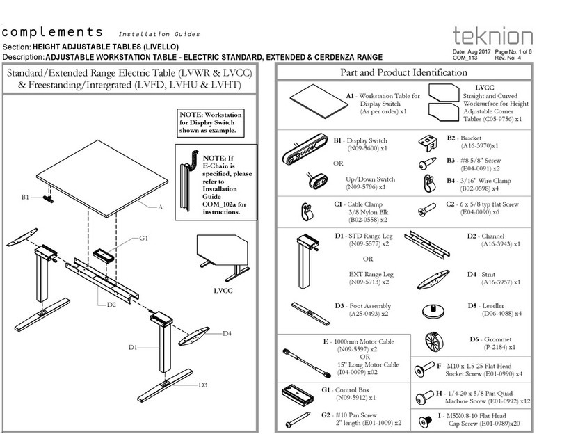
Teknion complements LIVELLO Operating and maintenance instructions
Teknion

Teknion complements LIVELLO Operating and maintenance instructions

Teknion Sidewise Series Operating and maintenance instructions

Teknion

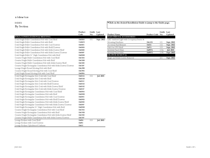
Teknion Sidewise Series Operating and maintenance instructions

Teknion Sabrina Owner's manual

Teknion

Teknion Sabrina Owner's manual
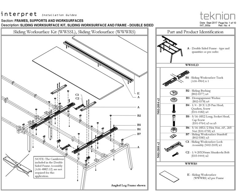
Teknion Interpret User manual

Teknion

Teknion Interpret User manual

Teknion zones Operating and maintenance instructions
Teknion

Teknion zones Operating and maintenance instructions

Teknion height-adjustable bench Operating and maintenance instructions

Teknion

Teknion height-adjustable bench Operating and maintenance instructions
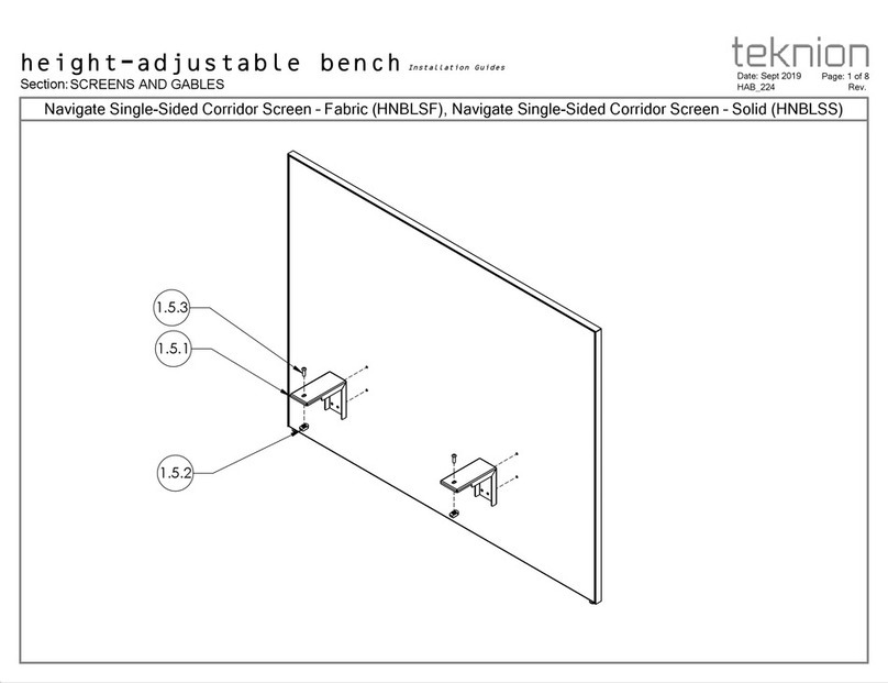
Teknion HNBLSF Operating and maintenance instructions

Teknion

Teknion HNBLSF Operating and maintenance instructions
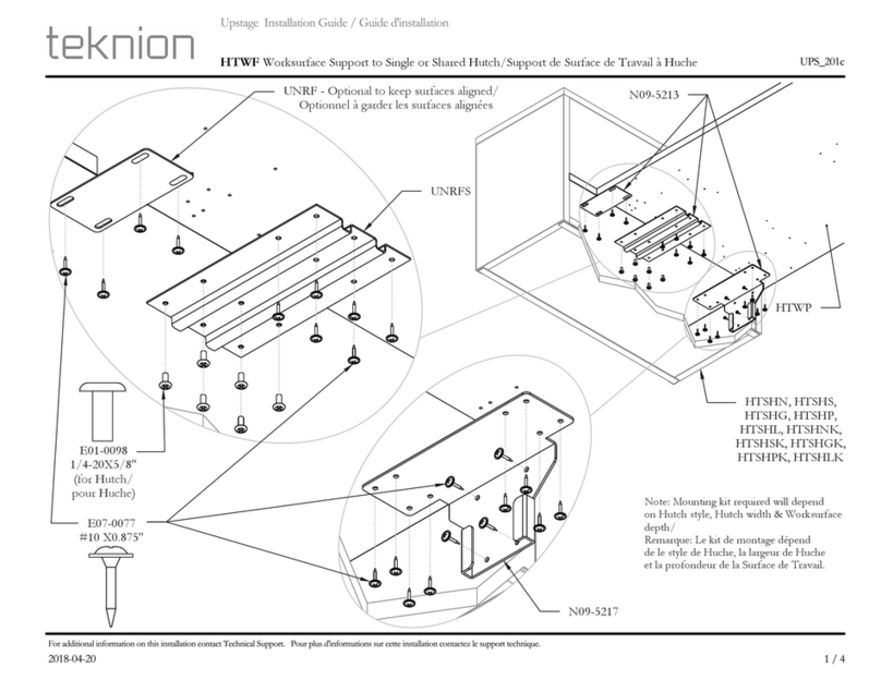
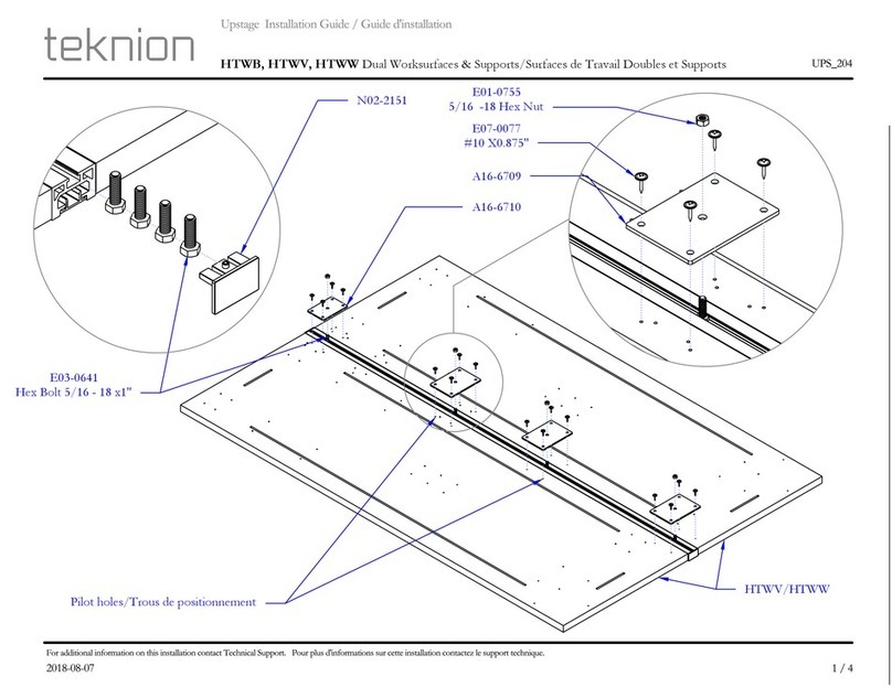
Teknion Upstage User manual

Teknion

Teknion Upstage User manual

Teknion District Series User manual

Teknion

Teknion District Series User manual

Teknion JNSESH User manual

Teknion

Teknion JNSESH User manual

Teknion Livello User manual

Teknion

Teknion Livello User manual
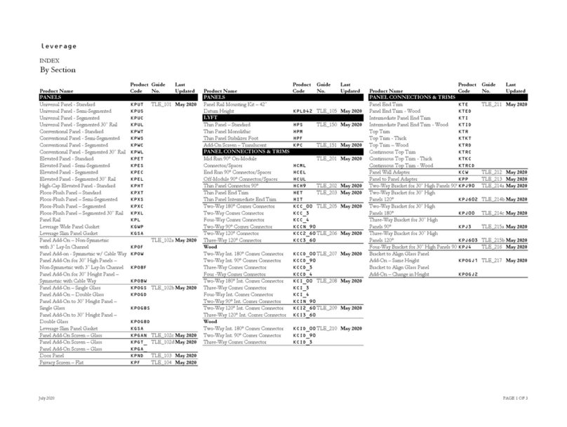
Teknion Leverage Operating and maintenance instructions

Teknion

Teknion Leverage Operating and maintenance instructions

Teknion north 56 User manual

Teknion

Teknion north 56 User manual

Teknion BCGRLB User manual

Teknion

Teknion BCGRLB User manual
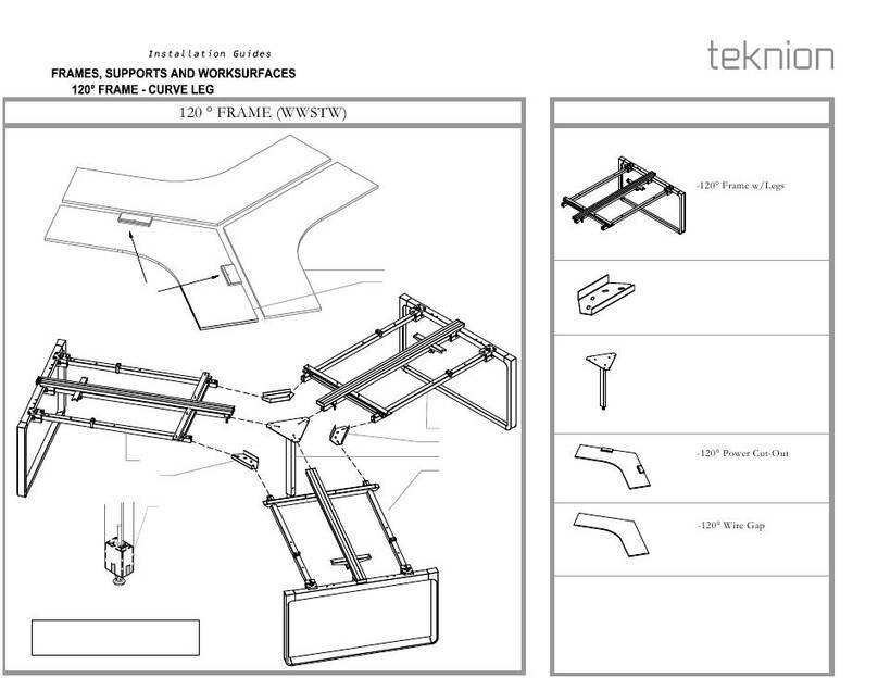
Teknion interpret 120 FRAME CURVE LEG WWSTW User manual
Teknion

Teknion interpret 120 FRAME CURVE LEG WWSTW User manual

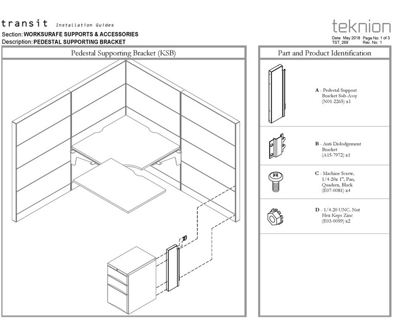
Teknion Transit KSB Operating and maintenance instructions
Teknion

Teknion Transit KSB Operating and maintenance instructions

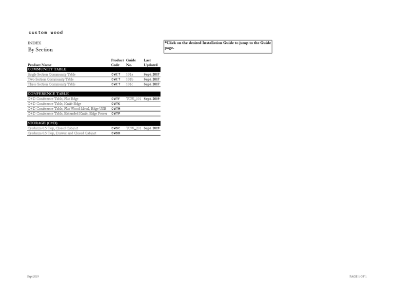
Teknion Custom wood CWCT Series Operating and maintenance instructions

Teknion

Teknion Custom wood CWCT Series Operating and maintenance instructions
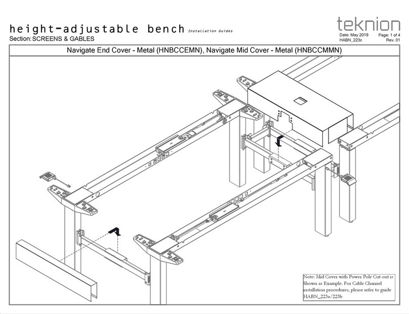
Teknion Navigate End Cover-Metal Operating and maintenance instructions

Teknion

Teknion Navigate End Cover-Metal Operating and maintenance instructions

Teknion XAFGM Series Operating and maintenance instructions

Teknion

Teknion XAFGM Series Operating and maintenance instructions
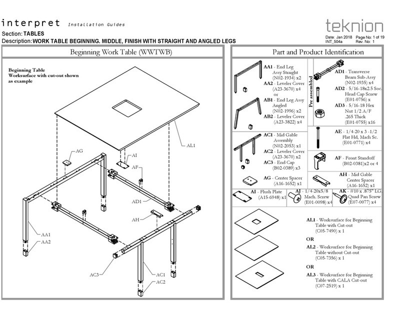
Teknion Beginning Work Table User manual

Teknion

Teknion Beginning Work Table User manual

Teknion Navigate 120 HA Frame HNBFNT Operating and maintenance instructions

Teknion

Teknion Navigate 120 HA Frame HNBFNT Operating and maintenance instructions

Teknion Interpret User manual

Teknion

Teknion Interpret User manual

Teknion HTWB User manual

Teknion

Teknion HTWB User manual

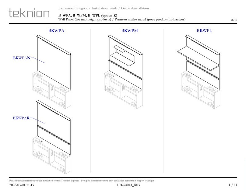
Teknion B WPA Series User manual

Teknion

Teknion B WPA Series User manual

Popular Indoor Furnishing manuals by other brands

HAMPTON BAY EDINGTON 141-012-CLCB-KD-NF Use and care guide
HAMPTON BAY

HAMPTON BAY EDINGTON 141-012-CLCB-KD-NF Use and care guide

Room & Board BERKLEY Assembly instructions

Room & Board

Room & Board BERKLEY Assembly instructions

Simpli Home WyndenHall Brooklyn + Max AXCART14-TB manual

Simpli Home

Simpli Home WyndenHall Brooklyn + Max AXCART14-TB manual

Simpli Home WyndenHall brooklyn + max AXCERN-12 manual

Simpli Home

Simpli Home WyndenHall brooklyn + max AXCERN-12 manual

Smart Flex SF-500 manual

Smart Flex

Smart Flex SF-500 manual
HumbleCrew Bright CT376 Assembly instructions
HumbleCrew

HumbleCrew Bright CT376 Assembly instructions

Knape&Vogt HM25 installation instructions

Knape&Vogt

Knape&Vogt HM25 installation instructions

Little Seeds Metal Bed with Casters 4395419LS Assembly manual
Little Seeds

Little Seeds Metal Bed with Casters 4395419LS Assembly manual

System Build 2484015COM Assembly instructions
System Build

System Build 2484015COM Assembly instructions

Jason.L Quadro Wood A 2P Run workstation 1200 mm Assembly instructions

Jason.L

Jason.L Quadro Wood A 2P Run workstation 1200 mm Assembly instructions

Happy Beds Sanderson 6FT Velvet Fabric Bed Assembly instructions

Happy Beds

Happy Beds Sanderson 6FT Velvet Fabric Bed Assembly instructions
WorkPro 12000 Series Assembly instructions and warranty information
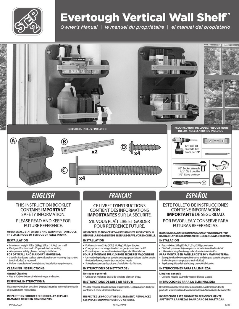
WorkPro

WorkPro 12000 Series Assembly instructions and warranty information

Step 2 Evertough Vertical Wall Shelf owner's manual
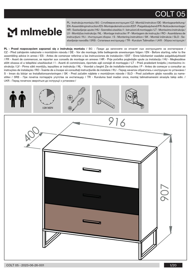
Step 2

Step 2 Evertough Vertical Wall Shelf owner's manual

mlmeble COLT 05 Assembling Instruction

mlmeble

mlmeble COLT 05 Assembling Instruction

LOWE'S 1954MR-22-278 manual

LOWE'S

LOWE'S 1954MR-22-278 manual

Herman Miller Canvas Vista Credenza Installation and Disassembly for Recycling Instructions

Herman Miller

Herman Miller Canvas Vista Credenza Installation and Disassembly for Recycling Instructions
HOMEDEPOT KF200189-01 manual

HOMEDEPOT

HOMEDEPOT KF200189-01 manual
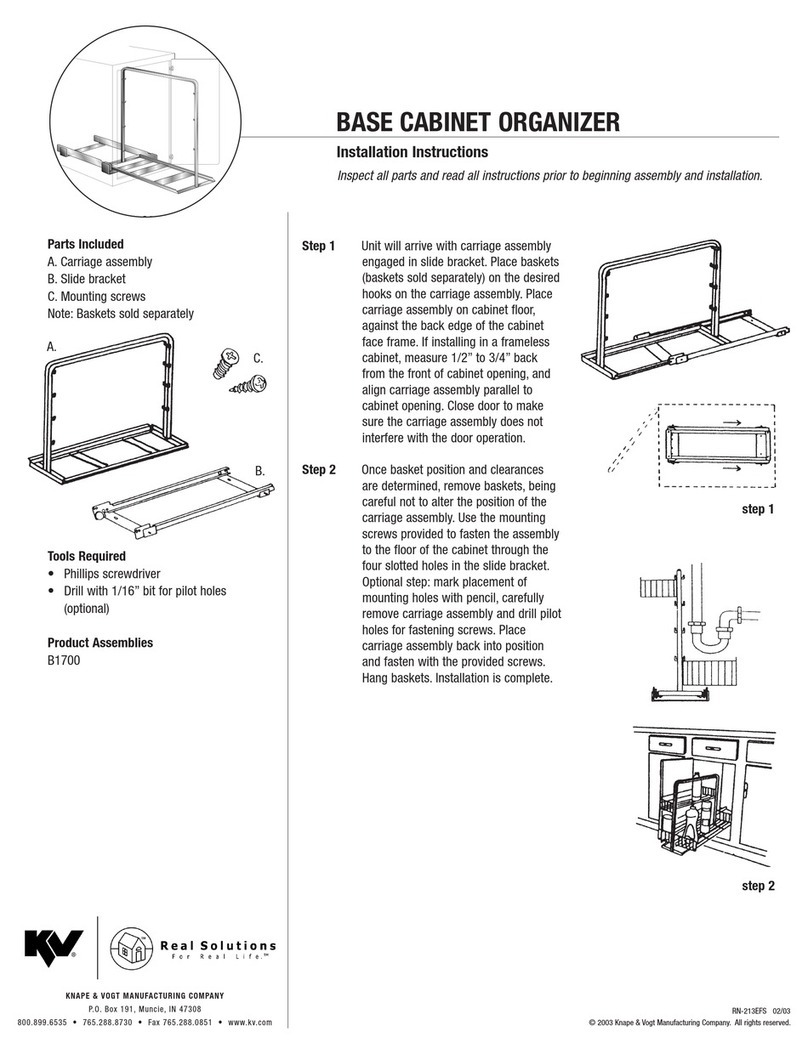
Knape&Vogt B1700 installation instructions

Knape&Vogt

Knape&Vogt B1700 installation instructions

manuals.online logo
manuals.online logoBrands
  • About & Mission
  • Contact us
  • Privacy Policy
  • Terms and Conditions

Copyright 2025 Manuals.Online. All Rights Reserved.