Teknion HABCGESL Operating and maintenance instructions
Section:
Description: Page No:
Date:
Rev. No: 06
SOLID GABLES & CABLE CHANNEL
SCREENS AND GABLES
Aug 2017 1 of 16
HABL_203b
height-adjustable bench
Installation Guides
A - (HABCGESL) x2
A1 - Inside Cover Assembly
for Wood End Gable
(N09-5187) x1 or
(N09-5188) x1
A4 - Bottom Bracket
(A16-3020) x2
A2 - Cover for End Gable
(C05-8862) x1
B - (HABFCC) x2
B1 - Center Rail
Extrusion Cap
(A23-5200) x1
B2 - Center Rail
Extrusion
(A21-0888\98) x1
B3 - Cable Channel
Assembly
(N09-5019) x1
B4 - Support Bracket
- Screen Rail
(A16-3009) x2
B5 - Hex Bolt 5/16
-18x1" Long ZP
(E03-0641) x8
B6 - 5/16-18 Hex Nut, 1/2
A/F, .265 Thick
(E01-0755) x8
B7 - Communication
Cover Plate
(A16-3127) x1
B8 - #8-18x1/2" Cross
Square COMB. Self
(E07-0012) x6 or x10
B9 - Cable Channel Cover
Plate (Single Cable
Management only)
(A16-3220) x2
B11 - Wire Manager Clip
(B02-2007) xqty
varies
B10 - Hanger
(A16-2364) x2
C - (HABCGMSL) x1
C1 - Side Cover Assembly
(C05-8921)x1 &(C05-8863)x1
or (C05-9034)x1 &(C05-9033)x1
or (C05-8863) x2
or (C05-9033) x2
C3 - Front Hanging
Bracket
(A16-3028) x2
C2 - Front
Cover
(C05-8864) x2
B2 B3
B4
A1
A2
C1
C2
C9
NOTE: Mid Gable Without
Power Pole shown as an example.
Wire Manager E-Chain
(N09-5138) ships with HAB
Cable Channel (HABFCC).
Please refer to Installation
Guide HABL_301 for
assembly instructions.
A3 - Hanging Bracket
(A16-3021) x2
A5 - 1/4-20 UNCx0.5" 2A,
Cross/SQ. COMB.
Socket, Truss. Head.
Mach. Screw. Steel
ZN (E01-0110) x4
C7 - 1/4-20 UNCx0.5" 2A, Cross/SQ. COMB.
Socket, Truss Head. Machine Screw, Steel
Zinc (E01-0110) x12
C4 - Bottom Bracket
for Mid Gable
(A16-3027) x2
C5 - Hanging Bracket
for Mid Gable
(A16-3203) x4
C6 - Bottom Connecting
Bracket
(A16-3026) x4
C8 - Top Cover w/Cutout
for Mid Gable w/Power
Pole
(A16-3087) x1
& Top Cover for Wood Mid
Gable w/Power Pole
(A16-3088) x1
C9 - Top Cover for Wood Mid Gable
(A16-3029) x2
B12 - 1/4-20x3/4" Mach
Screw, Black
Quad, Truss
(E01-0113) x8
A6 - #10X1/2" Tap
Scr Quad Pan
(E01-0023)x2
A7 - Gable
Connecting Plate
(A16-3651) x2
C10 - #10X1/2" Tap Scr
Quad Pan (E01-0023)x4
C11 - Gable Connecting Plate
(A16-3651) x4
C12 - Mid Gabel Bottom Angle Bar
(A16-3655)x2
C11
C12
A7
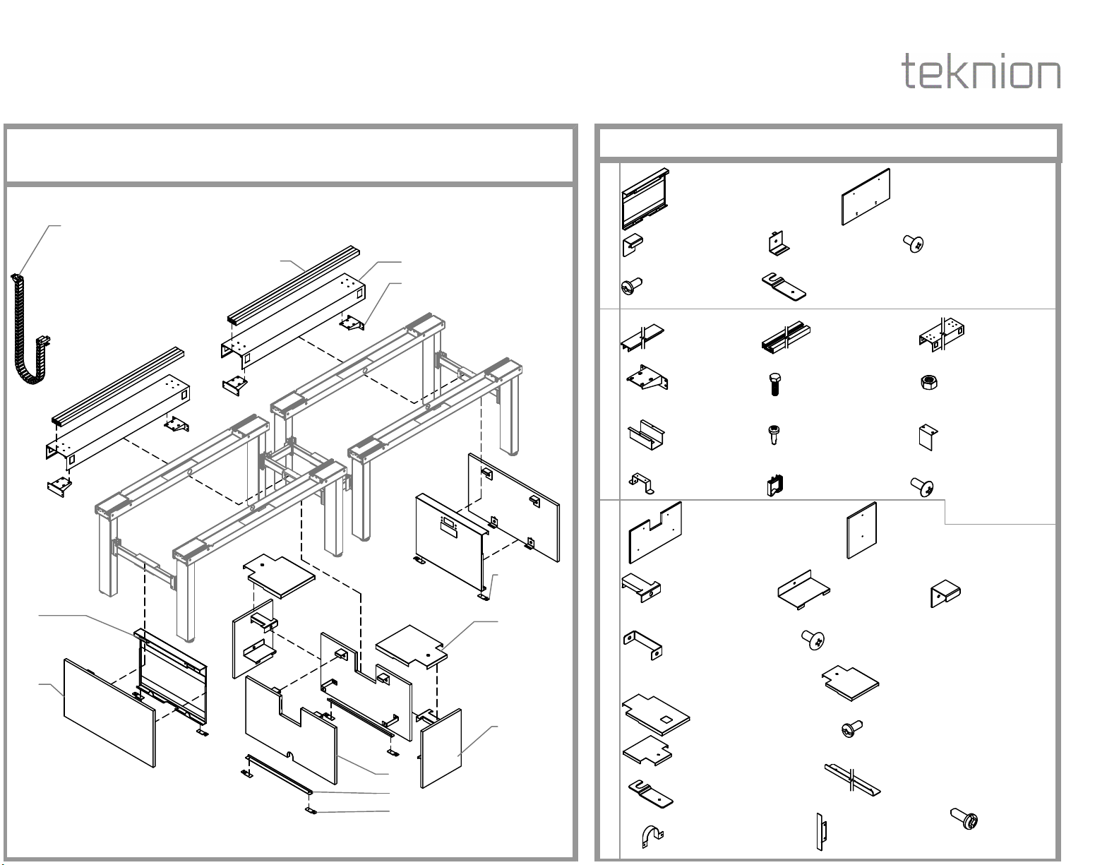
HAB End Gable-Solid (HABCGESL), HAB Cable
Channel (HABFCC) & HAB Mid Gable-Solid (HABCGMSL)
Part and Product Identification
C13- Cover Plate for
Basefeed Cut-Out
(A16-3690) x1
C14- Cover Plate for
Cable Cut-Out
(A16-3689) x4
C15- #6 Wood
Screw
(E04-0050)
xqty varies
Section:
Description: Page No:
Date:
REMOVE SUPPORT BRACKETS AND COMMUNICATION PLATE COVER
Aug 2017 2 of 16
HABL_203b
SOLID GABLES & CABLE CHANNEL
SCREENS AND GABLES
height-adjustable bench
Installation Guides
B3
B4
B6
B7 B8
STEP 1: Remove Support Brackets and Communication Plate Cover as shown.
Section:
Description: Page No:
Date:
ATTACH SUPPORT BRACKET APPLY FOAM RUBBERS
HABL_203b
3 of 16
Aug 2017
SOLID GABLES & CABLE CHANNEL
SCREENS AND GABLES
height-adjustable bench
Installation Guides
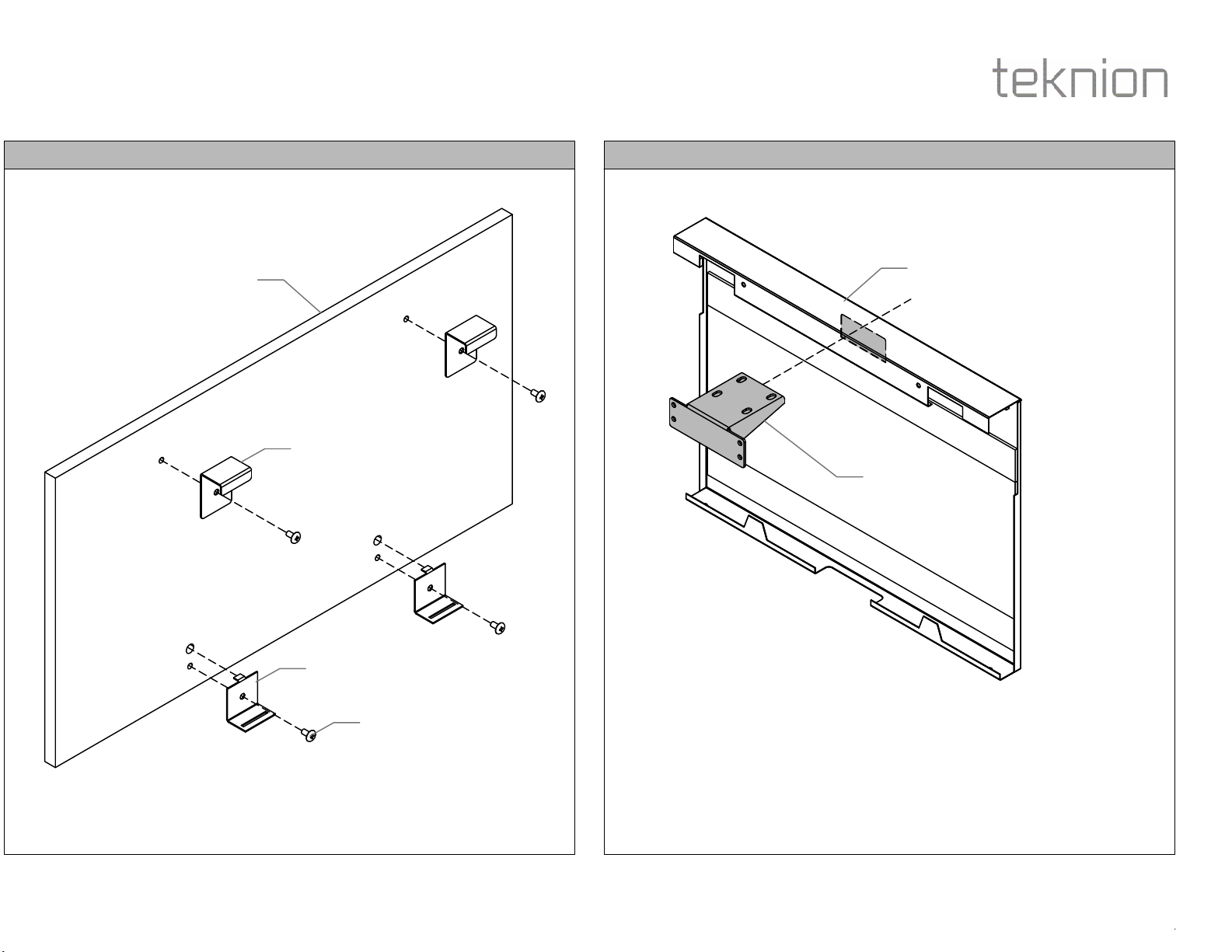
STEP 3: Insert Support Bracket through the cut-out on the Inside Cover Assembly as shown.STEP 2: Fasten Brackets to Outside Cover Assembly.
A2
A3
A1
B4
A4
A5

Section:
Description: Page No:
Date:
ATTACH CONNECTION PLATES TO FRAME LEGS
Aug 2017 4 of 16
HABL_203b
SOLID GABLES & CABLE CHANNEL
SCREENS AND GABLES
height-adjustable bench
Installation Guides
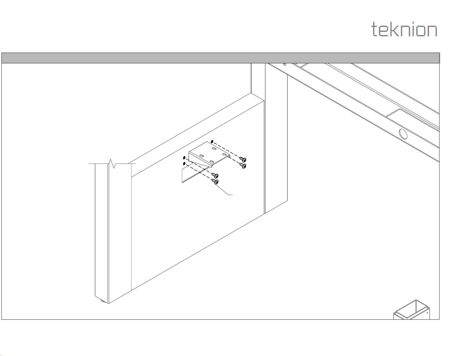
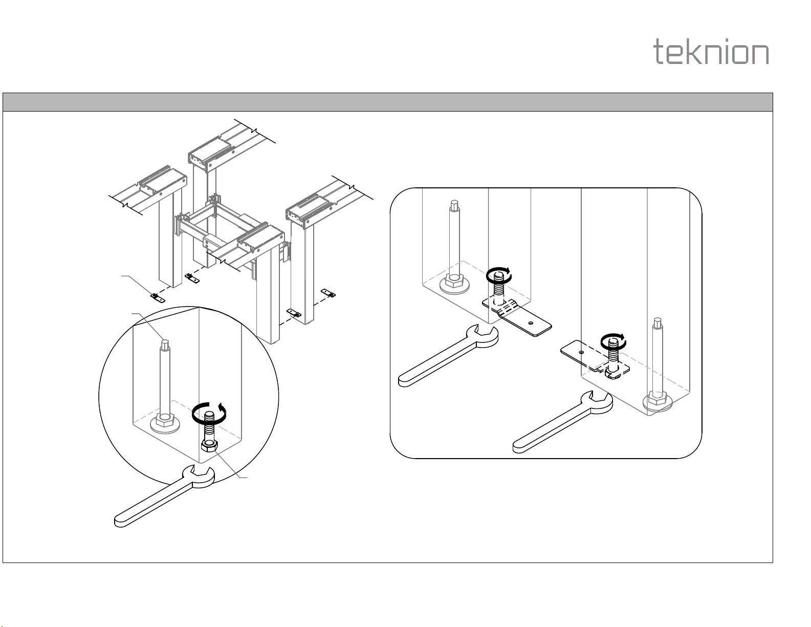
STEP 4: Loosen Legs Hex Bolt to allow enough room for Gable Connecting Plate. Fasten Gable Connecting Plates to Frame Legs.
A7
Leveler
Leg Hex Bolt
Please refer to Installation Guide
No. HABL_101a for
information.

Section:
Description: Page No:
Date:
MOUNT INSIDE COVER ASSEMBLY
Aug 2017 5 of 16
HABL_203b
SOLID GABLES & CABLE CHANNEL
SCREENS AND GABLES
height-adjustable bench
Installation Guides
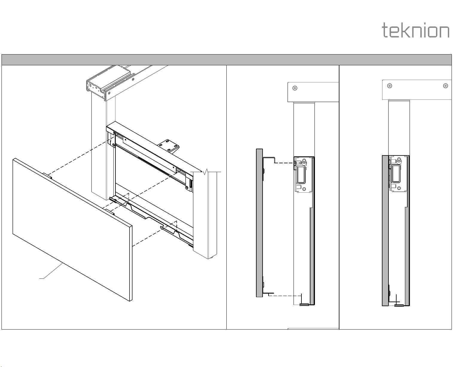
STEP 5: Mount Inside Cover Assembly onto Stretcher Bar. Make sure the face of the Inside Cover Assembly is flush with the Leg as shown in Section View. Secure Inside Cover Assembly to
Gable Connecting Plate on both sides using Tap Quad Pan screws provided.
Section View
A6
Section:
Description: Page No:
Date:
SECURE TO THE STRETCHER BAR
Aug 2017 6 of 16
HABL_203b
SOLID GABLES & CABLE CHANNEL
SCREENS AND GABLES
height-adjustable bench
Installation Guides
STEP 6: Secure Inside Cover Assembly to Stretcher Bar with Bolts.
B12
Opposite Side
Section:
Description: Page No:
Date:
MOUNT OUTSIDE COVER ASSEMBLY
Aug 2017 7 of 16
HABL_203b
SOLID GABLES & CABLE CHANNEL
SCREENS AND GABLES
height-adjustable bench
Installation Guides
STEP 7: Mount Outside Cover Assembly to the highlighted part of the Inside Cover Assembly as shown.
A2
Section View Section View
Section:
Description: Page No:
Date:
ATTACH CONNECTING PLATES TO FRAME LEGS
Aug 2017 8 of 16
HABL_203b
SOLID GABLES & CABLE CHANNEL
SCREENS AND GABLES
height-adjustable bench
Installation Guides
STEP 8: Loosen Legs Hex Bolt to allow enough room for Gable Connecting Plate. Fasten Gable Connecting Plates to Frame Legs.
C11
Leveler
Leg Hex Bolt

Section:
Description: Page No:
Date:
MOUNT BOTTOM ANGLE BAR
Aug 2017 9 of 16
HABL_203b
SOLID GABLES & CABLE CHANNEL
SCREENS AND GABLES
height-adjustable bench
Installation Guides
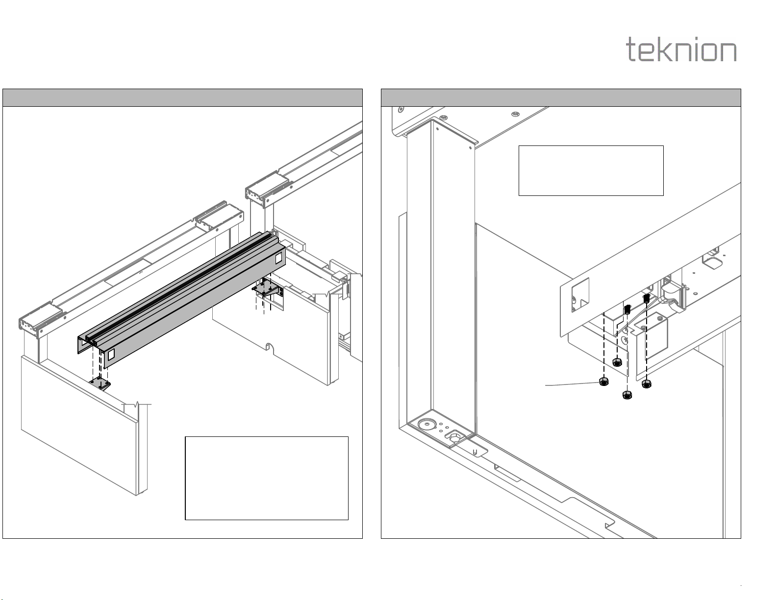
STEP 9: Mount Bottom Angle Bar and secure to Gable Connecting Plate on both sides using Tap Quad Pan screws provided.
C10
C12

Section:
Description: Page No:
Date:
MID POWER POLE SUPPORT PLATE ATTACH SUPPORT BRACKET
HABL_203b
10 of 16
Aug 2017
SOLID GABLES & CABLE CHANNEL
SCREENS AND GABLES
height-adjustable bench
Installation Guides
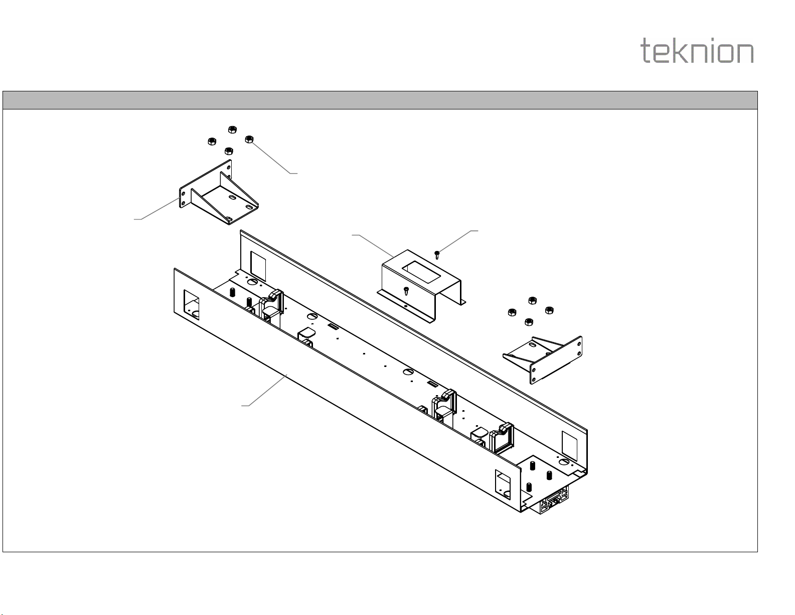
STEP 10: Fasten Brackets and Cover Plates to Side Cover Assemblies and Front Covers as
shown.
Optional: If Mid Power Pole is specified. Please fasten Connecting Bracket to the underside of
the Stretcher Bars as shown.
C3
C2
C1
C4
C6
C5
C7
Connecting
Bracket
Hex Bolt 5/16-18x1"
Long ZP
NOTE: Please refer to installation
guide HABL_302b for detail.
Underside View
C13
C14
C15
C15

Section:
Description: Page No:
Date:
MOUNT SIDE COVER ASSEMBLY SECURE SIDE COVER ASSEMBLY
HABL_203b
11 of 16
Aug 2017
SOLID GABLES & CABLE CHANNEL
SCREENS AND GABLES
height-adjustable bench
Installation Guides
STEP 12: Secure Support Bracket to Stretcher Bar with Bolts.
STEP 11: Mount Side Cover Assembly onto the Stretcher Bar as shown.
NOTE: Side Cover with Base Feed
Cut-out shown as an example.
NOTE: Please refer to
Specification Drawing to
mount the correct Side
Cover Assembly.

Section:
Description: Page No:
Date:
CABLE CHAIN ASSEMBLY
Aug 2017 12 of 16
HABL_203b
SOLID GABLES & CABLE CHANNEL
SCREENS AND GABLES
height-adjustable bench
Installation Guides
NOTE: Electrics
components have to
installed on Cable Channel
before connecting to
Support Bracket. Please
refer to Installation Guide
301, 302a or 302b for
corresponding Electrics
installation.
B3
B10
B7
B11
High Capacity
Power Module
Standard Power Module
Base Feed
Power Module
Cover
E-Chain
B9
B8
NOTE: Install Cable Channel
Cover Plate (B9) on Cable
Channel where E-Chain is not
specified or unused location.
Section:
Description: Page No:
Date:
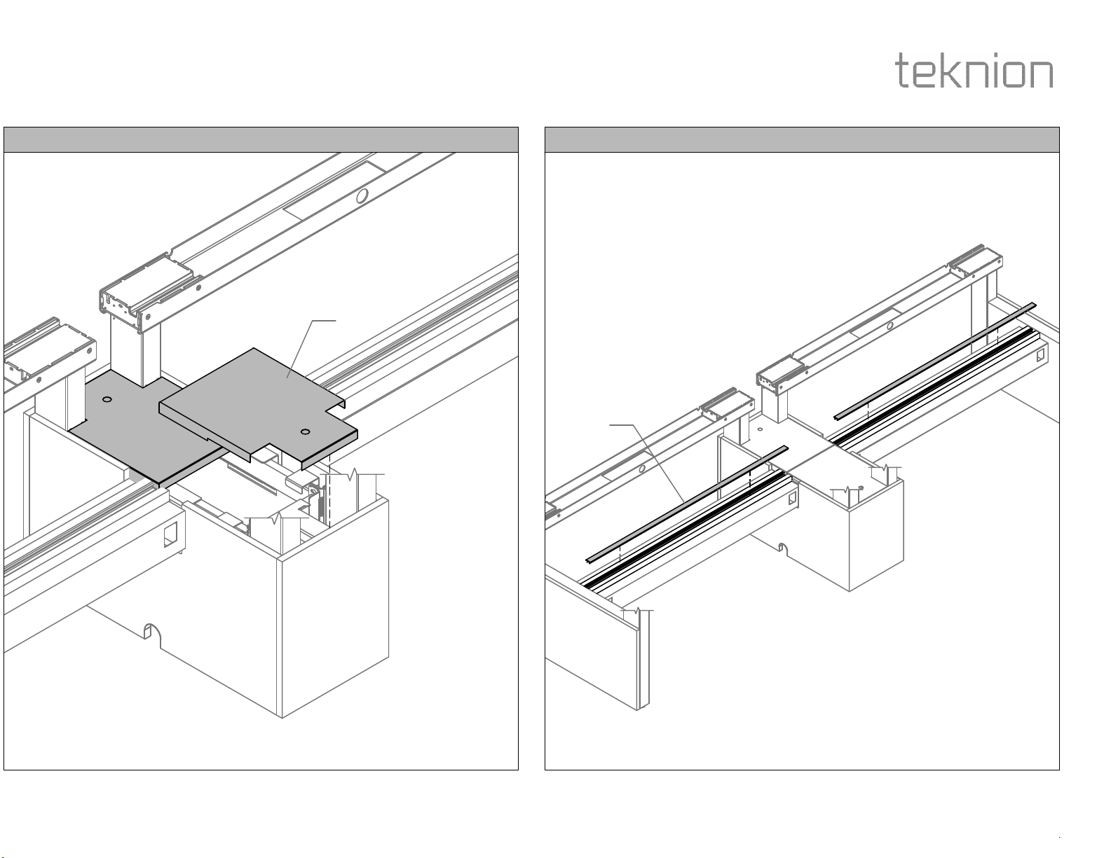
CABLE CHANNEL ASSEMBLY AND CENTER RAIL SECURE CABLE CHANNEL
HABL_203b
13 of 16
Aug 2017
SOLID GABLES & CABLE CHANNEL
SCREENS AND GABLES
height-adjustable bench
Installation Guides
STEP 14: Secure Cable Channel in place with Nuts.STEP 13: Align holes on Support Brackets, Cable Channel Assembly. Insert Bolts inside Center
Rail Extrusion through Cable Channel Assembly and Brackets as shown.
B6
Underside View
NOTE: Electrics components to be
installed on Cable Channel before
connecting to Support Bracket. Please
refer to Installation Guide 301a, 301b,
301c, 302a or 302b for corresponding
Electrics installation.
NOTE: Please repeat STEP 1 to
14 if second Cable Channel is
specified .
Section:
Description: Page No:
Date:
MOUNT FRONT COVER ASSEMBLIES
Aug 2017 14 of 16
HABL_203b
SOLID GABLES & CABLE CHANNEL
SCREENS AND GABLES
height-adjustable bench
Installation Guides
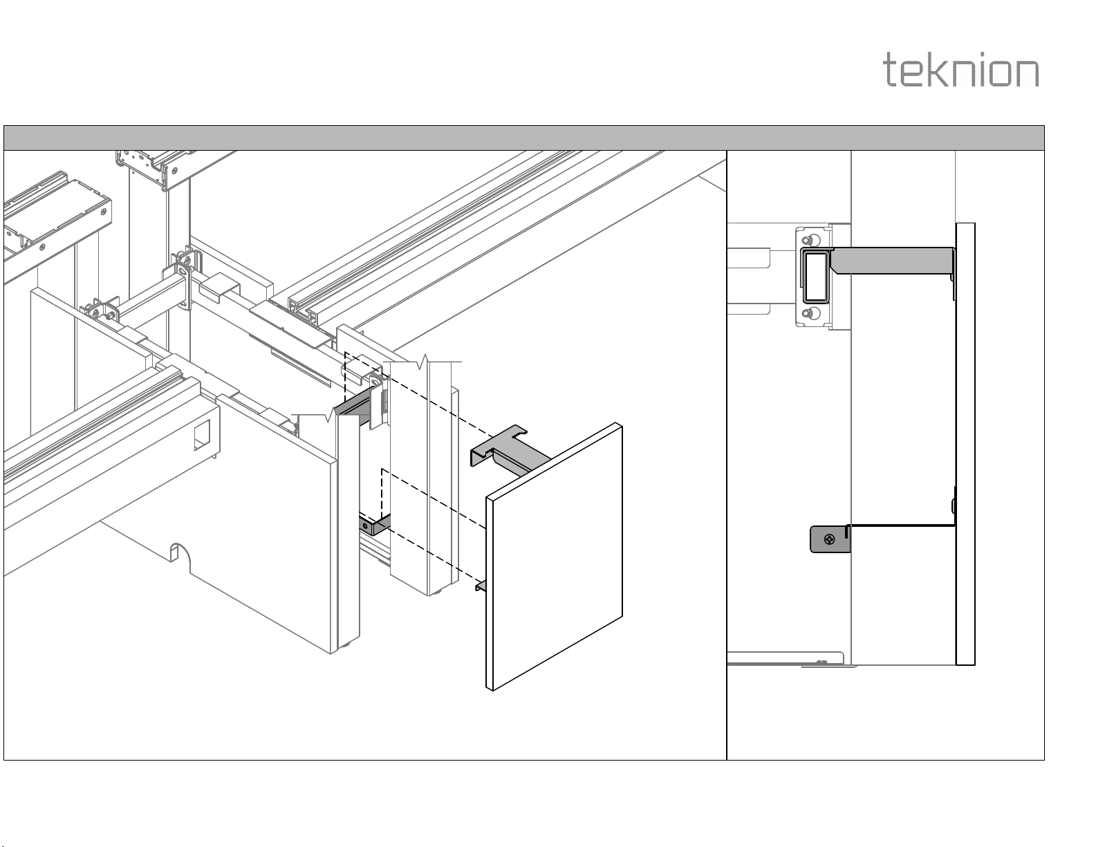
STEP 15: Mount Front Covers onto the Frame Link and Bottom Connecting Brackets.
Section View

Section:
Description: Page No:
Date:
TOP COVER W/ POWER POLE CUTOUT (OPTIONAL)
Aug 2017 15 of 16
HABL_203b
SOLID GABLES & CABLE CHANNEL
SCREENS AND GABLES
height-adjustable bench
Installation Guides
STEP 16a: If Mid Gable Power Pole is specified. Attach Top Covers onto the highlighted extrusions on the Side and Front Cover Assemblies as shown.
Repeat Step 1-14 to install End Gable and Cable Channel on another side of the Table.
C5
Section:
Description: Page No:
Date:
ATTACH TOP COVER CENTER RAIL EXTRUSION CAP
HABL_203b
16 of 16
Aug 2017
SOLID GABLES & CABLE CHANNEL
SCREENS AND GABLES
height-adjustable bench
Installation Guides
STEP 17: Insert Center Rail Extrusion Caps onto Center Rail Extrusions as shown.STEP 16b: Rest Top Covers onto Gable structures as shown.
C5
B1
This manual suits for next models
2
Other Teknion Office Equipment manuals


