TM 504
OPERATING
INSTRUCTIONS
INTRODUCTION
Description
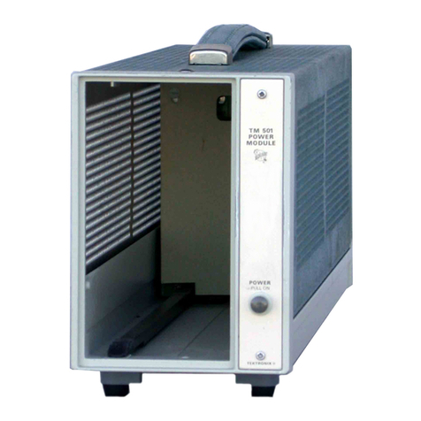
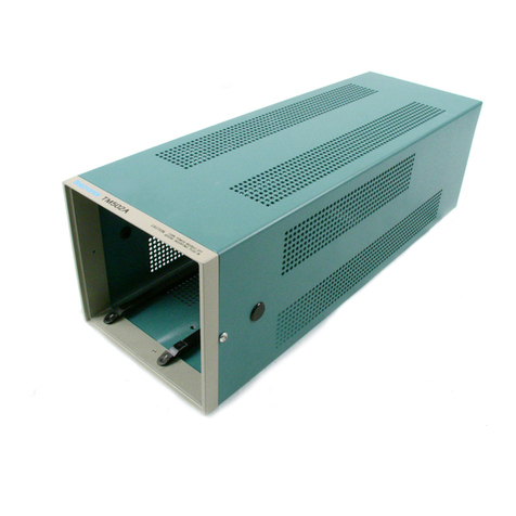
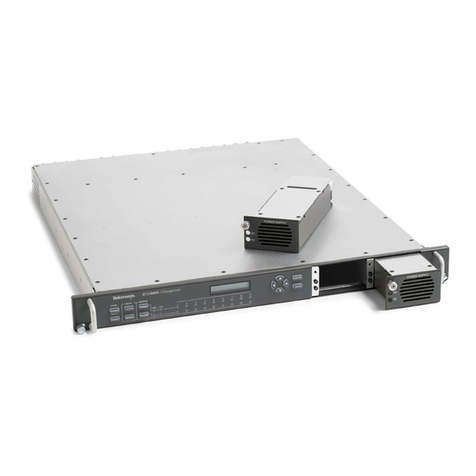
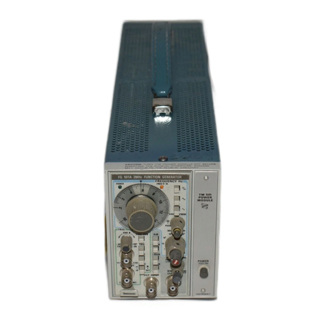
The TEKTRONIX TM-504 Power Module is amain-
frame for the TM 500 Series of Modular Instrumentation. It
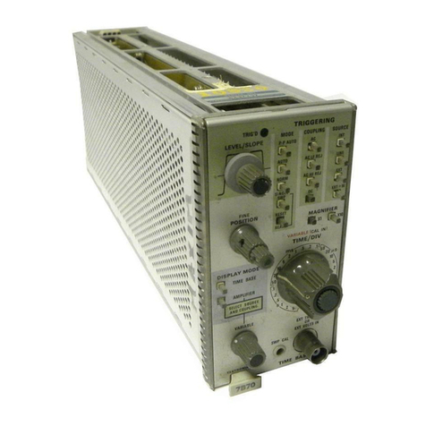
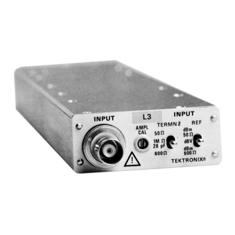
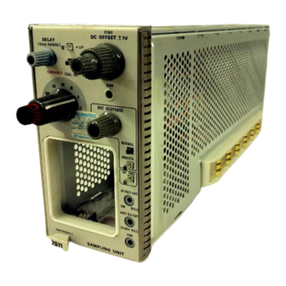
accepts up to four independently functional plug-in
modules to form acompact versatile and low cost instru-
mentation system. The TM 504 is abasic power source and
provides an interconnecting scheme for the other members
of the TM 500 Series family. Factory options allow
customer modification using signal access at the plug-in
module/power module interface to provide rear panel
inputs and outputs, and interconnections between compart-
ments.
Power Source
This instrument is designed to operate from apower
source with its neutral at or near earth (ground) potential
with aseparate safety-earth conductor. It is not intended
for operation from two phases of amulti-phase system, or
across the legs of asingle phase, three-wire system.
Power Usage
With four plug-in modules installed, the TM 504 can
require up to 220 Wof power at the upper limits of the
high line voltage ranges. Actual power consumption de-
pends on the particular module combination and operating
mode selected at any one time.
NOTE
The compartment closest to the PULL ON POWER
switch is high power. Some of the TM 500 Series
plug-in modules require high power to operate at
their maximum capabilities.
Operating Temperatures
The TM 504 can be operated in an ambient air
temperature of 0°C to 50°C. Thermal cutout devices
protect the system by disconnecting the power to the TM
504 Power Module when internal temperatures rise above a
safe operating level. These devices automatically return
power to the unit when the internal temperatures return to
asafe level.
Since the TM 504 can be stored in temperatures between
—40°C and +75°C, allow the instruments's chassis to return
to within the operating limits before applying power.
POWERING UP
Plug-In Modules
It is not necessary that all the plug-in compartments be
utilized in order to operate the Power Module. The only
modules needed are those necessary to accomplish the task.
Turn the Power Module off before inserting the plug-
in; otherwise, damage may occur to the plug-in
circuitry.
Module Installation
1.Check the location of the white plastic barriers on the
TM 504 interconnecting jack to ensure that their locations
match the slots in the edge of the plug-in module's circuit
board.
2. Align the plug-module chassis with the upper and
lower guides of the selected compartment. Push the module
in and press firmly to seat the circuit board in the
interconnecting jack. (Remove the plug-in module by
pulling on the white release latch located in the lower left
corner of each module.)
REV. B, MAR. 1975 4
