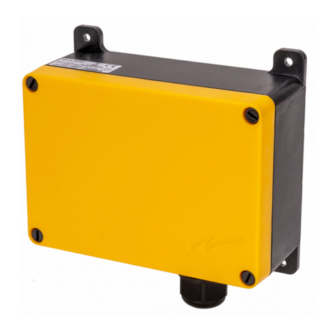
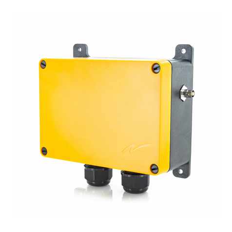
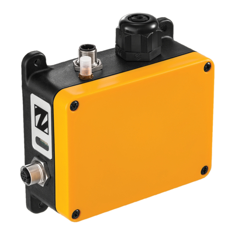
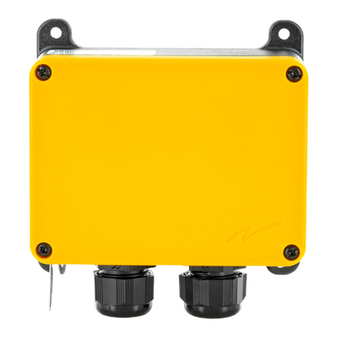
Tele Radio R20-01 User manual

safe smart strong
R20
ED-PM-RX102-EN-v02
Language: English (original)
ENDUSER
INSTRUCTIONS
Receivers: R20-01,
R20-04

©TeleRadioAB
Datavägen21
SE-43632Askim
Sweden
Phone:+46(0)317485460

Enduser instructions│ R20│
CHAPTER1:INTRODUCTION 4
1.1Aboutthisdocument 5
1.2Aboutthissystem 6
CHAPTER2:SAFETY 7
2.1Warnings&restrictions 7
CHAPTER3:FUNCTIONALSAFETY 10
CHAPTER4:TECHNICALDATA 12
4.1Systemspecifications 12
4.2Receiverspecifications 12
4.3Currentconsumption 14
CHAPTER5:PRODUCTGENERALDESCRIPTION 15
5.1Receiverdescription 15
CHAPTER6:STATUSANDERRORINDICATIONS 17
6.1Receiver'sStatuscode 17
6.2CANopen(DLEDs)runstatus 17
6.3CANopen(DLEDs)errorstatus 18
6.4J1939(DLEDs)runstatus 18
6.5J1939(DLEDs)errorstatus 18
CHAPTER7:OPERATION 19
7.1Generalinformation 19
7.2Registeratransmitterinareceiver 19
7.3Logalltransmittersoutwiththereceiver 21
CHAPTER8:BATTERY 22
8.1Batteryprecautions 22
8.2Batteryinformation 23
CHAPTER9:WARRANTY,SERVICE,REPAIRS,ANDMAINTENANCE 24
CHAPTER10:REGULATORYINFORMATION 25
10.1Europe 25
10.2NorthAmerica 25
10.3Radiomodule 28
ANNEX11:INDEX 29
ED-PM-RX102-EN-v02 3

Enduser instructions│ R20│ Chapter 1: Introduction
CHAPTER 1: INTRODUCTION
Thank you for using a Tele Radio AB product
READALLINSTRUCTIONSANDWARNINGSCAREFULLYBEFORE
OPERATINGTHEPRODUCTS.
TheseEnduserinstructionshavebeenpublishedbyTeleRadioABandarenotsubjectto
anywarranty.TheEnduserinstructionsmaybewithdrawnorrevisedbyTeleRadioABat
anytimeandwithoutfurthernotice.Correctionsandupdateswillbeaddedtothelatest
versionofthemanual.AlwaysdownloadtheEnduserinstructionsfromourwebsite,
www.tele-radio.com,forthelatestavailableversion.Keepthesafetyinstructionsfor
futurereference.
IMPORTANT!Theseinstructionsareintendedforendusers.Theinstructionscan
beprintedandhandedtoenduser.
TeleRadioABremotecontrolsareoftenbuiltintowiderapplications.Thisdocumentation
isnotintendedtoreplacethedeterminationofsuitabilityorreliabilityoftheproductfor
specificuserapplicationsandshouldnotbeusedforthispurpose.Itistheresponsibility
ofanysuchusersorintegratorstoperformtheappropriateandcompleteriskanalysis,
evaluationandtestingoftheproductswithrespecttotherelevantspecificapplicationor
use.TeleRadioABshallnotberesponsibleorliableformisuseoftheinformation
containedherein.
Alwaysrefertotheapplicablelocalregulationsforinstallationandsafetyrequirements
relatingtocranes,hoists,materialhandlingapplications,liftingequipment,industrial
machinery,and/ormobilehydraulicapplicationsusingTeleRadioABproducts,e.g.:
lapplicablelocalandindustrialstandardsandrequirements,
lapplicableoccupationalhealthandsafetyregulations,
lapplicablesafetyrulesandproceduresforthefactorywheretheequipmentisbeing
used,
luserandsafetymanualsorinstructionsofthemanufactureroftheequipment
whereTeleRadioABremotecontrolsystemsareinstalled.
TeleRadioABEnduserinstructionsdonotincludeoraddressthespecificinstructions
andsafetywarningsoftheendproductmanufacturer.
TeleRadioABproductsarecoveredbyawarrantyagainstmaterial,construction,or
manufacturingfaults.See"Chapter9:Warranty,service,repairs,andmaintenance".
4 ED-PM-RX102-EN-v02

Enduser instructions│ R20│ Chapter 1: Introduction
1.1About this document
Beforeinstallingoroperatingtheproduct,readthecorrespondingdocumentation
carefully.
TeleRadioAB'sproductrangeiscomposedoftransmitters,receivers,andaccessories
intendedforusetogetherasasystem.
R20systemsaremainlyintendedforthehydraulicandmobileequipmentmarkets.These
systemsarenotstandardizedbutcustomizedandadaptedtoeachcustomer'sneeds.
Howtheoutputsareconnectedtocontroltheobjectdependsoneachspecificinstallation
andwillnotbecoveredinthisdocument.Forexactdetails,seethetechnical
documentationprovidedforyourspecificsystem.Drawings,schematicsandconnection
diagramsareuniqueandarealsoprovidedtogetherwiththesystem.Imagesshownin
thisdocumentmaythereforenotshowtheexactpositionofbuttons,paddlesandarefor
illustrativepurposesonly.
TheseEnduserinstructionscovermaintechnicalspecifications,standardoperating
instructions.
Pleasereportanyerrororomissioninthisdocument,aswellasanyimprovementor
amendmentsuggestiontotd@tele-radio.com.
1.1.1COPYRIGHT
Informationinthisdocumentissubjecttochangewithoutnotice.Nopartofthis
publicationmaybereproduced,storedinaretrievalsystem,ortransmittedinanyformor
byanymeans,electronic,photographic,mechanical(includingphotocopying),recording
orotherwiseforanypurposeotherthanthepurchaser'spersonalusewithoutthewritten
permissionofTeleRadioAB.
1.1.2TERM AND SYMBOL DEFINITIONS
Thecapitalizedtermsandsymbolusedhereinshallhavethefollowingmeaning:
lWARNING:indicatesahazardoussituationwhich,ifnotavoided,couldresultin
deathorseriousinjury.
lCAUTION:indicatesahazardoussituationwhich,ifnotavoided,willresultin
minorormoderateinjury.
lIMPORTANT:isusedforinformationthatrequiresspecialconsideration.
lNOTE:isusedtoaddresspracticesnotrelatedtophysicalinjury.
Thissymbolisusedtocallattentiontosafetymessagesthatwouldbe
assignedthesignalwords"WARNING"or"CAUTION".
ED-PM-RX102-EN-v02 5

Enduser instructions│ R20│ Chapter 1: Introduction
1.2About this system
TeleRadioAB'sremotecontrolsystemsaresuitableforawidevarietyofapplicationsfor
e.g.stationaryormobileequipments,hydraulicmachines,construction,forestryor
agricultureequipmentsandmore.TeleRadioAB'stransmittersandreceiversarehighly
customizableandcanbeconfiguredtosuitthemostwide-rangingapplication
requirements&usagehabits.
R20systemsmeetthestrictestsafetystandardsandachievedproductcertifications
CAT3,PLeandSIL3inaccordancewithEN13849-1andIEC61508respectively.
1.2.1GENERATED SYSTEM NUMBER FOR CUSTOMIZED SYSTEMS
Eachcustomizedsystemhasitsowngeneratedsystemnumber.Itisimportanttokeep
thisnumberandtouseitinallcommunicationwithTeleRadioAB.
Thelabelwiththesystemnumber(SystemNo.)isaffixedontheproduct'soriginallabel.1
Thesystemnumberforeachproductis
writtenontheproductlabellocatedonthe
topsideofthehousing.
Recordyoursystemnumberhere:
1.2.2ABOUT R20 RECEIVERS
R20receivershaveduplexcommunicationandworkincontinuousmode.
Therearetwostandardmodelsthatcanbecustomizedwithseveralexpansionboards.
Connector Base
board
Expansion boards
35 pins2CAN RS485 A/D IOs 8-relay
R20-01 ●●○○○○
R20-04 ○●○○○○
●Standard○Optional
1.2.3COMPATIBILITY
ThisreceiveriscompatiblewithalltransmittersandreceiversinthePumarange.
1Theoriginalserialnumber(SN)isalsoindicatedonthenewlabel.
2Otherconnectorsavailableinoptions,eg.23pin,M12,etc.
6 ED-PM-RX102-EN-v02

Enduser instructions│ R20│ Chapter 2: Safety
CHAPTER 2: SAFETY
2.1Warnings & restrictions
Carefullyreadthroughthefollowingsafetyinstructionsbefore
proceedingwiththeinstallation,configuration,operation,or
maintenanceoftheproduct.Failuretofollowthesewarningscouldresult
indeathorseriousinjury.
ThisproductmustnotbeoperatedwithouthavingreadandunderstoodtheEnduser
instructions,thespecifictechnicaldocumentation(forcustomizedsystems),andhaving
receivedtheappropriatetraining.Thepurchaserofthisproducthasbeeninstructedhow
tohandlethesystemsafely.Thefollowinginformationisintendedforuseasa
complementtoapplicablelocalregulationsandstandards.
IMPORTANT!TeleRadioABremotecontrolsareoftenbuiltintowider
applications.Thesesystemsshouldbeequippedwith:
•awiredemergencystopwherenecessary
•abrake
•anaudibleorvisualwarningsignal
2.1.1OPERATION
Thisradiosystemmustnotbeusedinareaswherethereisariskof
explosion.
Onlyqualifiedpersonnelshouldbepermittedtoaccessthetransmitter
andoperatetheequipment.
Theusershould:
ED-PM-RX102-EN-v02 7

Enduser instructions│ R20│ Chapter 2: Safety
lAlwaysfollowoperatingandmaintenanceinstructionsaswellasall
applicablesafetyproceduresandrequirements.
lDonotopenthereceiverencapsulationunlessyouarequalified.
lYoumustsatisfytheagerequirementsinyourcountryforoperating
theequipment.
lItisstrictlyprohibitedtooperatetheequipmentundertheinfluence
ofdrugs,alcoholand/ormedications.
lAlwaystestthetransmitterstopbuttonbeforeoperatingit.Pressthe
stopbuttonthentwistandpullitout.Thistestshouldbedoneon
eachshift,withoutaload.
lNeveruseatransmitterifthestopbuttonismechanically
damaged.Contactyoursupervisororrepresentativeforservice
immediately.
lNeverleavethetransmitterunattended.
lAlwaysswitchthetransmitteroffwhennotinuse.Storeinasafe
place.
lKeepaclearviewoftheworkareaatalltimes.
2.1.2MAINTENANCE
Beforemaintenanceinterventiononanyremotecontrolledequipments:
•alwaysremoveallelectricalpowerfromtheequipment.
•alwaysfollowlockoutprocedures.
lKeepthesafetyinformationforfuturereference.AlwaysdownloadtheEnduser
instructionsfromourwebsite,www.tele-radio.com,forthelatestavailableversion.
lIferrormessagesareshown,itisveryimportanttofindoutwhatcausedthem.
Contactyourrepresentativeforhelp.
lThefunctionalityofthestopbuttonshouldbetestedatleastafterevery200hours’
use.
lIfthestopbuttonismechanicallydamaged,donotusethetransmitter.Contact
yoursupervisororrepresentativeforserviceimmediately.
lDonottrytoopentheencapsulation.
lAlwayscontactyourrepresentativeforserviceandmaintenanceworkonthe
product.
lKeepcontactsandantennasclean.
8 ED-PM-RX102-EN-v02

Enduser instructions│ R20│ Chapter 2: Safety
lWipeoffdustusingaclean,slightlydamcloth.
lNeverusecleaningsolutions.
lChecktheencapsulation,foilsandcablefordamageseveryday.Ifyouusethe
productalthoughtheencapsulationorfoilisdamaged,moisturecancauseserious
damagetotheelectronics.
ED-PM-RX102-EN-v02 9

Enduser instructions│ R20│ Chapter 3: Functional safety
CHAPTER 3: FUNCTIONAL SAFETY
Stop function
Thesafety-relatedstopfunctionintheradiosystemcomplieswithENIEC61508:2010
SIL3andENISO13849-1:2015Category3PLe.Thestoprelaysonthereceiverunit
arecontrolledbythestopbuttononthetransmitterunit.Whenthestopbuttonispressed,
thestoprelaysinterruptthepowertothesafety-relatedapplication.Thecompleteend
usersystem,includingtheradiosystem,entersasafestate.Thedefaultresponsetime
forthestopfunctionis500ms.
ThestopfunctionissupportedbyallreceiversandtransmittersinthePumarange.
Applicable products
Thefollowingtransmittersaredesignedtocomplywiththeappointedsafety
requirementswhenusedtogetherwithaR20receiver:
lT24
Installation
Thestoprelaysonthereceiverunitmustbecorrectlyinstalledontheendusersystem,to
ensurethatopened/deactivatedstoprelaysinterruptthepowertothesafety-related
application.Thesafetylevelofthestopfunctioncanonlybecreditedwhenintegratedina
completeend-usersystemthatcomplieswithequalorhighersafetylevels.
Configuration
Thedefaultconfigurationofthereceiverunitcomplieswiththeappointedsafety
requirements.Configurationoftheresponsetimeforthestopfunction(bydefault500ms)
mustbejustifiedwithavalidriskanalysisinordertomaintainthesafetylevels.
Achieved performance level (PL)
Safety function MTTFd (years) DCavg(%) Category Achieved PL
Stopfunction 100 99 3 e
10 ED-PM-RX102-EN-v02

Enduser instructions│ R20│ Chapter 3: Functional safety
Measures for probability of hardware failures
Measure System based on…
T24 + R20 T24 + R21
Probabilityofdangerousfailureper
hour
PFH=39FIT PFH=28FIT
Diagnosticcoverage DC=99% DC=99%
Safefailurefraction SFF=99% SFF=99%
Levelofhardwarefaulttolerance HFT=1 HFT=1
Prooftestinterval 10years 10years
Diagnostictestinterval Continuous Continuous
1FIT=1failure/109h
ED-PM-RX102-EN-v02 11

Enduser instructions│ R20│ Chapter 4: Technical data
CHAPTER 4: TECHNICAL DATA
NOTE:Theinformationbelowmaydifferincustomizedsystems,pleaserefertothe
correspondingtechnicaldocumentationprovidedwitheachsystem.
4.1System specifications
Radiofrequencyband 2405–2480MHz
Frequencymanagement DirectSequenceSpreadSpectrum(DSSS)
FieldStrengthAdaptationFeature
NumberofChannels 16(channel11–26)
Range(typical) 100m(328ft),adjustabledependingonconfiguration
Systemaddress 32bit–4294967295possibilities
Dataformat 250kbit/s
Hammingdistance 6
Operatingtemperature -20…+70°C(-4…+158°F)
Storagetemperature -30…+80°C(-22…+176°F)
Pairing(registration) Easytopairwithouttoolsandwithoutopeningthereceiver
housing.
Bluetooth(configurable
option)
Bluetoothconnectivityforconfiguration&settingsviathe
WebandmobileApp.
Configuration Displaymenu
4.2Receiver specifications
4.2.1COMMON SPECIFICATIONS
R20
Powersupply[operating
voltage]
12–24VDC[-50%…+35%],max.40A
Operatingvoltage 6–32VDC
Numberofstoprelays
Max.resistiveload
2,fail-safe&redundant(potentialfree)
10A,250VAC(10A,30VDC)
Availableslotsfor
expansionboards
61
1E.g.I/Osexpansionboard(digitaland/oranalogue)or8-relayexpansionboard(NO/NC)
12 ED-PM-RX102-EN-v02

Enduser instructions│ R20│ Chapter 4: Technical data
R20
Numberoflogicaldigital
inputs
upto4
Numberoflogicaldigital
outputs
upto2
Max.numberof
selectable&combinable
I/Osonbaseboard
26(6SIO+20PWM)
NumberofSafeI/Os upto71x10A
NumberofPWMI/Os upto20x4A
Bussystem/com.
protocols
standard: –
optional: RS485(ModbusRTU)
CAN(J1939orCANopen)
Radiocommunication Duplex
Radiofrequencyoutput
power
EIRP2<12.5dBm(18mW)
Antenna Internal(externalpassiveandactiveantennasinoption)
Max.numberofregistered
transmitters
32
Datalogger 64Mbitlogmemory
Backupbattery33VLithium(CR2032)
Powerprotection Built-inreversepolarity,overvoltageandundervoltage
protections
Fuse Selfresetting
Safetylevels ENIEC61508SIL3,ENISO13849-1CAT3PLe(Stop
function)
IPcode IP66
Dimensions 209x147x71mm/8.2x5.8x2.8in
Weight(typical) 800g/1.8lbs
1OfthesevenSIO,one(SIO_VBAR)isdedicatedtopowersupply.
2Equivalentisotropicradiatedpower
3Forclockbackupincaseofpowerdisruption/failure.See"8.2Batteryinformation"
ED-PM-RX102-EN-v02 13

Enduser instructions│ R20│ Chapter 4: Technical data
4.2.2OTHER SPECIFICATIONS
R20-01 R20-04
Frontplatewithnoholes – ●
35-pinconnector ● ○
M12pinconnector1○ ○
Internalantenna ● ●
Externalantenna ○ ○
RP-SMAconnector2○ ○
Expansionboards ○ ○
RFID ○ ○
Cablebackup ○ ○
●Standard○Optional–:Notavailable
4.3Current consumption
Thetestwasperformedwithonlythebaseandbottomboards.Thetestwasperformed
withonlythebaseboardandoneCANboard.Thesamesettingswereappliedonallthe
PWMoutputsofthebaseboard.
Input power R20-01, R20-04
Min.* Max.**
12VDC 112mA 333mA
24VDC 65mA 233mA
*Minimumcurrentconsumption=receiverpowered,noactiverelaysand/oroutputs,no
radiosessionestablished.
**Maximumcurrentconsumption=receiverpowered,allrelaysand/oroutputsonthe
receiveractive,radiosessionestablished.
1MaleM12connectorforCAN.FemaleM12connectorforRS485/activeantenna.
2Forexternalpassiveantennas.
14 ED-PM-RX102-EN-v02

Enduser instructions│ R20│ Chapter 5: Product general description
CHAPTER 5: PRODUCT GENERAL DESCRIPTION
NOTE:Thepicturesshowninthischapterareforillustrativepurposesonly.Depending
ontheconfiguration,theactualproductappearancemaydifferfromthebasicmodel
usedforreference.
5.1Receiver description
1. LED
indicators
2. Capacitivesensorbutton(Cap
sensorbutton)
3. 35-pinconnector*
(Dependingon
models)
*See"1.2.2AboutR20receivers".
5.1.1LED INDICATORS
ThereceiverhasacapacitivebuttonincludingsevenLEDsshowingthereceiverstatus.
ED-PM-RX102-EN-v02 15

Enduser instructions│ R20│ Chapter 5: Product general description
1. StatusLEDs1–5: LED1(red):Registered
transmitterandradiolinkstatus
LED2(yellow):Transmitterlogin
status
LED3(green):Notused
LED4(orange):Notused
LED5(blue):Bluetoothconnection
status
2. CANstatusLEDs DLED1:CANinterface1(inoption)
DLED2:Notused
3. Capacitivesensorbutton(Capsensorbutton)
5.1.2MOUNTING DIMENSIONS
NOTE:Forcableglandsandcablediameterusedincustomizedsystems,pleaserefer
tothecorrespondingtechnicaldocumentationprovidedwitheachsystem.
16 ED-PM-RX102-EN-v02

Enduser instructions│ R20│ Chapter 6: Status and error indications
CHAPTER 6: STATUS AND ERROR INDICATIONS
6.1Receiver's Status code
LEDs1–5indicateerrorsandstatusforthereceiver,DLEDs1–2indicateerrorsandstatus
forCANopen.
LED Color Off On Flashing Indicates
1 red ● Oneormoretransmittersisregistered,radio
linkestablished
○ Notransmitterisregistered
●Oneormoretransmittersisregistered,noradio
link.
2 yellow ● Onetransmitterisloggedin
○ Notransmitterisloggedin
3 green – – – Notused
4 orange – – – Notused
5 blue ● Bluetoothactivated,communication
established
○ Bluetoothisnotactivatedinthesettings
slow Bluetoothinstand-by
fast Bluetoothinparingmode(registering)
6.2CANopen (DLEDs) run status
DLED
color
On Flickering ( red/
green alternately)
Single flash Blinking
Green Operational
state LSS Stoppedstate Pre-operationalstate
ED-PM-RX102-EN-v02 17

Enduser instructions│ R20│ Chapter 6: Status and error indications
CANopen
communication state
Description
Operational Stateforprocessdatatransmission.
LSS LSSservicesinprogress.
Stopped Exceptfornodeguardingorheartbeatmessages,anode
cannottransmitorreceiveanyothermessagesinthisstate.
Pre-operational StatefortheconfigurationofCANopendevices.PDO
communicationisnotpossibleinthisstate.
6.3CANopen(DLEDs) error status
DLED
color
On Flickering (red/
green alternately)
Single flash Double flash Triple flash
Red Busoff LSS Warninglimit
reached
Errorcontrol
event Syncerror
Contactyourrepresentativeforassistance.
6.4J1939 (DLEDs) run status
DLED color On Single flash
Green Operational Noaddress
J1939 communication
state
Description
Operational Addressclaimiscorrect,processingmessages.
Noaddress Addressclaimisstillrunningorhasfailed.
6.5J1939(DLEDs) error status
DLED color On Single flash
Red Busoff Warninglimitreached
Contactyourrepresentativeforassistance.
18 ED-PM-RX102-EN-v02

Enduser instructions│ R20│ Chapter 7: Operation
CHAPTER 7: OPERATION
7.1General information
Tocontrolareceiver,thetransmittermustberegisteredandloggedintothereceiver.If
anothertransmitterisalreadyloggedintothereceiver,itmustbeloggedoutbeforea
differenttransmittercanbeloggedin.
Morethanonetransmittercanberegisteredinthereceiver,butonlyonetransmittercan
beloggedinatatime.
7.2Register a transmitter in a receiver
Registeringmeansestablishingcommunicationbetweenthetransmitterandthereceiver.
R20receiverscanhaveupto32registeredtransmitters.
NOTE:Theregistrationinstructionsrequireaccesstothereceiverhousing.Forthe
registrationproceduretobesuccessful,thereceivermustbepoweredup.
RISKOFUNINTENDEDEQUIPMENTOPERATION
Onlytransmittersthatareintendedforuseshouldberegisteredinthe
receiver.
Failuretofollowtheseinstructionscouldresultindeath,seriousinjury,
orequipmentdamage.
RISKOFUNINTENDEDEQUIPMENTOPERATION
Donotperformthisactionwhenthereceiverisinasessionwithanother
transmitter.Theradiocommunicationmaybeinterruptedorbroken.
Failuretofollowtheseinstructionscouldresultindeath,seriousinjury,
orequipmentdamage.
ED-PM-RX102-EN-v02 19

Enduser instructions│ R20│ Chapter 7: Operation
OntheReceiver OntheTransmitter
1. Powerthereceiverup.
LED1isflashing(red)
.IfBluetooth
hasbeenactivated,theLED5will
alsoflash(blue).
2. PressandholdtheCapsensor
buttonuntilLED1stopsflashing.
LEDs2–5flash(fast).
3. ReleasetheCapsensorbutton.
LEDs1–5flash(slow).
Thereceiverisnowinregistration
mode.
Ifnoregistercommandisreceived
within30seconds,thereceiverwill
exitregistrationmode.1
4. MakesurethattheStopbuttonis
pressed.
5. Turnthekeyswitchtothe'On'
position(horizontal).
6. TwistandreleasetheStopbutton.
Theinitialstart-uplogois
displayed.Batteryindicator(s)light
(s).Thedisplayshows:
[Session
Selection].
7. EnterMenumode(seecorresponding
transmitter'smanual).
8. Navigatetothe[Register]menu
usingtheUp/Downbuttons.
9. PresstheSelectbuttontoenter.
10. Choosealocationforthereceiverto
beregisteredinusingtheUp/Down
buttons.
11. PresstheSelectbuttontoselect.
A+signisdisplayedinfrontofthe
selectedlocation.
12. PresstheBackbuttontoaccept.
Thedisplayshows:
[Registration
in progress…]
Whenthetransmitter'sregistercommandisreceived,…
OntheReceiver OntheTransmitter
LEDs1–5flash(fast). Thedisplayshows:
[Confirm
registration on the receiver].
12. PresstheCapsensorbuttonforat
least2s.
LEDs1–5flashthreetimes.
Thedisplayshows:
[Registration
successful. Transmitter was
registered in HY-RX-xxxxx].
Thetransmitterisnowregistered.
1Itisalsopossibletoexitregistrationmodebybrieflytouchingthereceiver'scapsensorbutton.
20 ED-PM-RX102-EN-v02
This manual suits for next models
1
Table of contents
Other Tele Radio Receiver manuals

Tele Radio
Tele Radio R4-01 User manual

Tele Radio
Tele Radio T20RX-02AKL User manual

Tele Radio
Tele Radio R2-01 User manual

Tele Radio
Tele Radio PN-R15-1 User manual

Tele Radio
Tele Radio R23-01 User manual

Tele Radio
Tele Radio T50 User manual

Tele Radio
Tele Radio R21-RS02 User manual

Tele Radio
Tele Radio T60RX-01APL User manual

Tele Radio
Tele Radio TG-R4-1 User manual

Tele Radio
Tele Radio T60 User manual