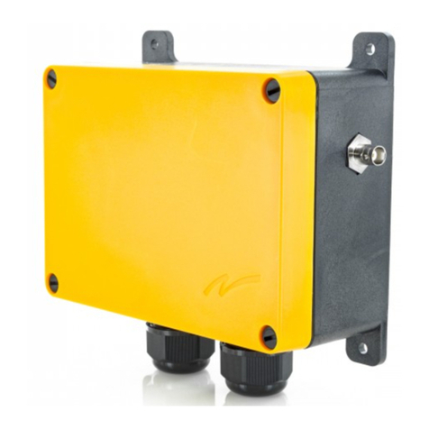
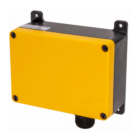
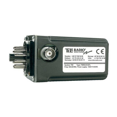
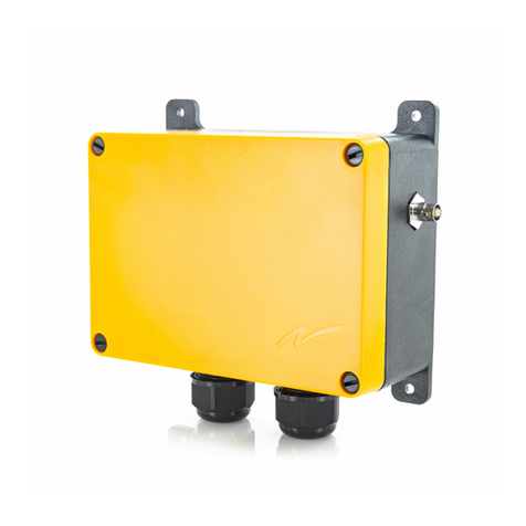
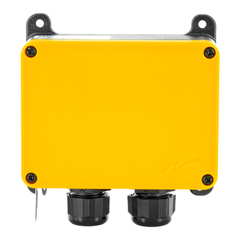
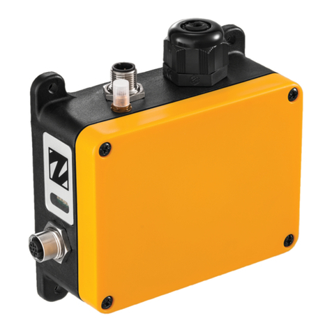
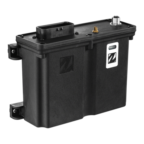
Tele Radio T20RX-02AKL User manual

safe smart strong
T 2 0
T 6 0
T20RX-02AKL
T20RX-02AKM T20RX-03ASL,
T20RX-03ASM
INSTALLATION
INSTRUCTIONS
Receivers:
IM-T20T60-RX101-EN-v02
Language: English (original)
With transmitters T20TX-01NKL, T20TX-02NKM , T20TX-02NKL,
T20TX-02NKM , T20TX-03NKL, T20TX-03NKM, T20TX-15DMM, T20TX-
15SMM; T60TX-0*STL, T60TX-0*STM, T60/T8-50, T60/T8-51, T60/T8-
52, T60/T8-53

©Tele Radio AB
Datavägen 21
SE-436 32 Askim
Sweden
Phone: +46 (0)31 748 54 60

Installation instructions│T20RX│
CONTENTS
CHAPTER 1: INTRODUCTION 5
1.1About this document 7
1.2About T20 receivers 8
CHAPTER 2: SAFETY 9
2.1Warnings & restrictions 9
CHAPTER 3: TECHNICAL DATA 12
3.1T20RX-02AKL, T20RX-02AKM 12
3.2T20RX-03ASL, T20RX-03ASM 13
CHAPTER 4: PRODUCT GENERAL DESCRIPTION 14
4.1T20RX-02AKL, T20RX-02AKM 14
4.2T20RX-03ASL, T20RX-03ASM 16
4.3Installation precautions 18
4.4Placement of antenna 19
CHAPTER 5: BOARD DESCRIPTION 20
5.1Base board – T20RX-02AKL, T20RX-02AKM 21
5.2Base board – T20RX-03ASL, T20RX-03ASM 23
CHAPTER 6: LED INDICATIONS 25
6.1T20RX-02ASK, T20RX-02ASM 25
6.2T20RX-03ASL, T20RX-03ASM 25
CHAPTER 7: OPERATION 26
7.1General information 26
CHAPTER 8: CONFIGURATION 27
8.1About ID code programming 27
8.2T20RX-02AKL, T20RX-02AKM 28
8.3T20RX-03ASL, T20RX-03ASM 31
CHAPTER 9: COMPATIBLE TRANSMITTERS 34
9.1Battery precautions 34
9.2T20TX-0*NKL, T20TX-0*NKM transmitters 35
9.3T60-T8-5* transmitters 37
9.4T60TX-0*STL, T60TX-0*STM transmitters 39
9.5T20TX-15DMM, T20TX-15SMM transmitters 42
CHAPTER 10: WARRANTY, SERVICE, REPAIRS, AND MAINTENANCE 45
IM-T20T60-RX101-EN-v02 3

Installation instructions│T20RX│Chapter 1: Introduction
CHAPTER 1: INTRODUCTION
Thank you for purchasing a Tele Radio AB product
READ ALL INSTRUCTIONS AND WARNINGS CAREFULLY BEFORE MOUNTING,
INSTALLING, CONFIGURING ANDOPERATING THE PRODUCTS.
These Installation instructions have been published by Tele Radio AB and are not
subject to any guarantees. The Installation instructions may be withdrawn or
revised by Tele Radio AB at any time and without further notice. Corrections and
updates will be added to the latest version of the manual. Always download the
Installation instructions from our website, www.tele-radio.com, for the latest
available version. Keep the safety instructions for future reference.
IMPORTANT! These instructions are intended for installers and authorized service
and distribution centers. The instructions containing information about the
installation and configuration of the radio remote control unit on the machine are
NOT intended to be passed on to the end user. Only information that is needed to
operate the machine correctly by radio remote control may be passed on to the
end user.
Tele Radio AB remote controls are often built into wider applications. This
documentation is not intended to replace the determination of suitability or
reliability of the product for specific user applications and should not be used for
this purpose. It is the responsibility of any such users or integrators to perform the
appropriate and complete risk analysis, evaluation and testing of the products with
respect to the relevant specific application or use. Tele Radio AB shall not be
responsible or liable for misuse of the information contained herein.
Always refer to the applicable local regulations for installation and safety
requirements relating to cranes, hoists, material handling applications, lifting
equipment, industrial machinery, and/or mobile hydraulic applications using Tele
Radio AB products, e.g.:
lapplicable local and industrial standards and requirements,
lapplicable occupational health and safety regulations,
lapplicable safety rules and procedures for the factory where the equipment is
being used,
luser and safety manuals or instructions of the manufacturer of the
equipment where Tele Radio AB remote control systems are installed.
IM-T20T60-RX101-EN-v02 5

Installation instructions│T20RX│Chapter 1: Introduction
Tele Radio AB Installation instructions do not include or address the specific
instructions and safety warnings of the end product manufacturer.
Tele Radio AB products are covered by a warranty against material, construction, or
manufacturing faults. See "Chapter 10: Warranty, service, repairs, and maintenance".
6 IM-T20T60-RX101-EN-v02

Installation instructions│T20RX│Chapter 1: Introduction
1.1About this document
Before installing or operating the product, read the corresponding documentation
carefully.
Tele Radio AB's product range is composed of transmitters, receivers, and
accessories intended for use together as a system.
These Installation instructions cover general safety issues, main technical
specifications, standard installation, configuration and operating instructions, and
general troubleshooting. Images shown in this document are for illustrative
purposes only.
Please report any error or omission in this document, as well as any improvement
or amendment suggestion to td@tele-radio.com.
1.1.1TERM AND SYMBOL DEFINITIONS
The capitalized terms and symbol used herein shall have the following meaning:
lWARNING: indicates a hazardous situation which, if not avoided, could result
in death or serious injury.
lCAUTION: indicates a hazardous situation which, if not avoided, will result in
minor or moderate injury.
lIMPORTANT: is used for information that requires special consideration.
lNOTE: is used to address practices not related to physical injury.
This symbol is used to call attention to safety messages that would be
assigned the signal words "WARNING"or "CAUTION".
IM-T20T60-RX101-EN-v02 7

Installation instructions│T20RX│Chapter 1: Introduction
1.2About T20 receivers
T20RX receivers have simplex communication and work in discontinuous mode.
1.2.1T20RX-02AKL AND T20RX-02AKM
The receiver units T20RX-02AKL and T20RX-02AKM are aimed for applications where
a maximum of two relay functions is needed. The receiver units T20RX-02AKL T20RX-
02AKM are similar but operate in the 433MHZ and 869 MHz radio frequency range
respectively.
1.2.2T20RX-03ASL, T20RX-03ASM
The receiver units T20RX-03ADL, T20RX-03ADM and T20RX-03ADM are aimed for use
in door automation applications, particularly when there is a need to control the
functions OPEN, STOP and CLOSE.
The receiver units T20RX-03ASL T20RX-03ASM are similar but operate in the 433MHZ
and 869 MHz radio frequency range respectively.
The receiver unit T20RX-03ADM is similar to T20/T60RX-03ADL but operates in 869
MHz.
8 IM-T20T60-RX101-EN-v02

Installation instructions│T20RX│Chapter 2: Safety
CHAPTER 2: SAFETY
2.1Warnings & restrictions
Carefully read through the following safety instructions before
proceeding with the installation, configuration, operation, or
maintenance of the product. Failure to follow these warnings could
result in death or serious injury.
This product must not be operated without having read and understood the
Installation instructions, the specific technical documentation (for customized
systems), and having received the appropriate training. The purchaser of this
product has been instructed how to handle the system safely. The following
information is intended for use as a complement to applicable local regulations
and standards.
IMPORTANT! Tele Radio AB remote controls are often built into wider
applications. These systems should be equipped with:
• a wired emergency stop where necessary
• a brake
• an audible or visual warning signal
2.1.1INSTALLATION AND COMMISSIONING
IMPORTANT! Only licensed or qualified personnel should be permitted to install
the product.
This radio system must not be used in areas where there is a risk of
explosion.
Always switch off all electrical power from the equipment before
installation procedure.
To utilize the safety features of the system, use the stop relays in the
safety circuitry of the object/ equipment to be controlled.
IM-T20T60-RX101-EN-v02 9

Installation instructions│T20RX│Chapter 2: Safety
When the equipment controlled by the receiver's standard relays is
connected via the stop relays, make sure that the maximum current
through the stop relays is still within the specifications. Contact your
representative for assistance.
RISK OF UNINTENDED EQUIPMENT OPERATION
Only transmitters that are intended for use should be registered in the
receiver.
Failure to follow these instructions could result in death, serious injury,
or equipment damage.
RISK OF ELECTRIC SHOCK
The receiver must only be opened by qualified installers or authorized
personnel.
Make sure the power supply is switched off before opening the receiver.
Failure to follow these instructions could result in death, serious injury,
or equipment damage.
lThe receiver must be securely attached and located where it will not
be hit by e.g. any moving parts.
lDo not install the product in areas affected by strong vibrations
lCable glands and vent plugs must face downwards to prevent water
ingress.
lEnsure that the power supply is connected to the correct terminals.
lEnsure that flexible cords and cables are not damaged through
friction or stress.
lDo not use damaged cables.
lEnsure cables and connectors do not hang loose.
lThe receiver is designed to withstand normal weather conditions but should
be protected from extreme conditions.
lMount the receiver in a location where the LEDs are easily visible and the
buttons accessible.
lMake sure to install available accessories inside or on the receiver before
permanently installing the receiver. A permanent installation of the product
10 IM-T20T60-RX101-EN-v02

Installation instructions│T20RX│Chapter 2: Safety
must include fuse protection of the equipment and cables against short
circuits.
2.1.2OPERATION
Only qualified personnel should be permitted to access the transmitter
and operate the equipment.
lMake sure that the user satisfies the age requirements in your
country for operating the equipment.
lMake sure that the user is not under the influence of drugs, alcohol
and medications.
lMake sure that the user knows and follows operating and
maintenance instructions as well as all applicable safety procedures
and requirements.
The user should:
lNever leave the transmitter unattended.
lAlways switch the transmitter off when not in use. Store in a safe
place.
lKeep a clear view of the work area at all times.
2.1.3MAI NTENANCE
Before maintenance intervention on any remote controlled equipments:
• always remove all electrical power from the equipment.
• always follow lockout procedures.
lKeep the safety information for future reference. Always download the
Installation instructions from our website, www.tele-radio.com, for the latest
available version.
lIf error messages are shown, it is very important to find out what caused
them. Contact your representative for help.
lKeep contacts and antennas clean.
lWipe off dust using a clean, slightly damp cloth.
lNever use cleaning solutions.
lCheck the encapsulation, foils and cable for damages. If the encapsulation or
foil is damaged, moisture can cause serious damage to the electronics.
IM-T20T60-RX101-EN-v02 11

Installation instructions│T20RX│Chapter 3: Technical data
CHAPTER 3: TECHNICAL DATA
3.1 T20RX-02AKL, T20RX-02AKM
Technical data T20RX-02AKL T20RX-02AKM
Power supply 12–24V AC/DC
Current consumption 30–80mA
Function relays 2 (potential free*, 10A 250V AC)1
Radio frequency band 433.92 MHz 869.85 MHz
IP code IP65
Operating temperature -20…+55°C / -4…+130°F (humidity 10–90%)
Dimensions 54 x 96 x 37mm
Weight (typical) 100 g
Antenna BNC connector, antenna in option2
Compatible transmitter(s) T20, T60
* Potential free means that a supply voltage is needed to get voltage out of a relay.
1Maximum load is indicated for resistive load only.
2Selectable antenna in option (433 or 869 MHz): ¼ antenna ½ antenna 5/8 antenna Dipole antenna PCB
antenna
12 IM-T20T60-RX101-EN-v02

Installation instructions│T20RX│Chapter 3: Technical data
3.2T20RX-03ASL, T20RX-03ASM
Technical data T20RX-03ASL T20RX-03ASM
Power supply 12–24 V AC/DC
Current consumption 30–80 mA
Function relays 3 (potential free*, 10A 250V AC)1
Radio frequency band 433.92 MHz 869.85 MHz
IP code IP66
Operating temperature -20…+55°C / -4…+130°F
Dimensions 120 x 116 x 50mm/ 4.72 x 4.6 x 1.97in
Weight (typical) 500 g (without antenna)
Antenna BNC connector, external antenna in option2 (preferably
dipole antenna for DIN-receivers and 1/2 – or 1/4-
antenna for wall mounting)
Compatible transmitter(s) T20, T60
* Potential free means that a supply voltage is needed to get voltage out of a relay.
1Maximum load is indicated for resistive load only.
2Selectable antenna in option: ¼ antenna, ½ antenna, 5/8 antenna, dipole antenna, PCB antenna.
IM-T20T60-RX101-EN-v02 13

Installation instructions│T20RX│Chapter 4: Product general description
CHAPTER 4: PRODUCT GENERAL DESCRIPTION
NOTE: The pictures shown in this chapter are for illustrative purposes only.
Depending on the configuration, the actual product appearance may differ from
the basic model used for reference.
4.1T20RX-02AKL, T20RX-02AKM
4.1.1RECEIVER DESCRIPTION
1. BNCconnector for external antenna
2. Cable glands (M20x1.5)
14 IM-T20T60-RX101-EN-v02

Installation instructions│T20RX│Chapter 4: Product general description
4.1.2MECHANI CAL INSTALLATION
IM-T20T60-RX101-EN-v02 15

Installation instructions│T20RX│Chapter 4: Product general description
4.2T20RX-03ASL, T20RX-03ASM
4.2.1RECEIVER DESCRI PTION
1. BNCconnector for external antenna
2. Cable glands (M20x1.5)
16 IM-T20T60-RX101-EN-v02

Installation instructions│T20RX│Chapter 4: Product general description
4.2.2MECHANICAL INSTALLATION
IM-T20T60-RX101-EN-v02 17

Installation instructions│T20RX│Chapter 4: Product general description
4.3Installation precautions
RISK OF ELECTRIC SHOCK
The receiver must only be opened by qualified installers or authorized
personnel.
Make sure the power supply is switched off before opening the receiver.
Failure to follow these instructions could result in death, serious injury,
or equipment damage.
IMPORTANT! Only authorized personnel should install the product.
Only correct installation complies with the safety levels for the product.
lA permanent installation of the receiver must include fuses in order to
protect the equipment and cables from short circuit.
lThe receiver must be installed vertically, on a flat and rigid surface, with the
cable at the bottom.
lMount the receiver in a location where the LEDs are easily visible and the
button on the receiver accessible.
lConsider the wiring limitation and the radio communication limitation to
choose the receiver location.
lEnsure no obstacle is impairing the radio communication performance
between the receiver and the transmitter.
lThe receiver must not be installed inside closed metal containers.
lMake sure any accessories inside or on the receiver are installed before
permanently installing the receiver.
lTest the equipment before installing the receiver permanently.
18 IM-T20T60-RX101-EN-v02

Installation instructions│T20RX│Chapter 4: Product general description
4.4Placement of antenna
NOTE: For optimum performance, place the receiver /antenna well away from
metal objects such as metal girders, high-voltage cables and other antennas.
lAntenna without cable (fig. on the left)
If the receiver is installed on a wall, the antenna should be angled away from
the wall.
lDipole antenna (fig. in the middle)
The dipole antenna with three meter coaxial cable must be installed
vertically.
l5/8 antenna with cable (fig. on the right)
The 5/8 antenna with three meter coaxial cable can be positioned freely and
high above the ground.
IM-T20T60-RX101-EN-v02 19

Installation instructions│T20RX│Chapter 5: Board description
CHAPTER 5: BOARD DESCRIPTION
NOTE: The pictures shown in this chapter are for illustrative purposes only.
Depending on the configuration, the actual product appearance may differ from
the basic model used for reference.
RISK OF ELECTRIC SHOCK
The receiver must only be opened by qualified installers or authorized
personnel.
Make sure the power supply is switched off before opening the receiver.
Failure to follow these instructions could result in death, serious injury,
or equipment damage.
IMPORTANT! Only experienced electronic technicians should add and map
expansion boards and inputs/outputs.
20 IM-T20T60-RX101-EN-v02
This manual suits for next models
3
Table of contents
Other Tele Radio Receiver manuals

Tele Radio
Tele Radio R2-01 User manual

Tele Radio
Tele Radio TG-R4-1 User manual

Tele Radio
Tele Radio T60RX-01APL User manual

Tele Radio
Tele Radio T50 User manual

Tele Radio
Tele Radio R20-01 User manual

Tele Radio
Tele Radio R23-01 User manual

Tele Radio
Tele Radio PN-R15-1 User manual

Tele Radio
Tele Radio R9 User manual

Tele Radio
Tele Radio R4-01 User manual

Tele Radio
Tele Radio T60 User manual