manuals.online logo
Brands
  1. Home
  2. •
  3. Brands
  4. •
  5. Televes
  6. •
  7. Antenna
  8. •
  9. Televes DINOVA T-Force BOSS MIX User manual

Televes DINOVA T-Force BOSS MIX User manual

MATV
Antenna / Antena
Ref. 144289
Kit 144286
- DINOVA BOSS MIX antenna (F connector)
- Indoor 2 output PSU (F connectors)
- Hardware kit: Wall support, U bolt, Bracket, 2
wing nuts, Screw on F-connector,
Weather boot cover & Datasheet.
- Antena DINOVA BOSS MIX (conector F)
- Alimentación de interior 2 sal. (conectores F)
- Accesorios: Soporte pared, Tornillo U, Mordaza,
2 palomillas, Conector, Capuchón y
Folleto.
Box contents / Contenido de la caja
Attach the antenna to the wall support, tighten the wing nuts, aim the antenna towards the transmitter and then secure. Fully extend the telescopic rods.
Instale la antena en el soporte pared, apriete ligeramente los tornillos, oriente la antena hacia el emisor y fíjela. Finalmente extienda las varillas telescópicas.
HORIZONTAL
VERTICAL
Mounting instructions / Instrucciones de montaje
KIT COMPOSITION
144286 Antenna 144289 + P.S.U. 550104
P.S.U.
Alimentación
1/8” (3mm)
9/32” (7mm)
DINOVA
Keep the PSU away from heat, moisture or excessive dust, avoiding long cable runs with antenna.
Proteja la alimentación de la humedad, calor y polvo, y evite largas longitudes de cable hasta la antena.
Use the weather boot cover (outdoor installation)
Utilice el capuchón impermeable (inst. exteriores)
Typical application
Aplicación típica
VERTICAL HORIZONTAL
Recommendation / Recomendación
Aim the antenna using the optimum line
of site toward theTV station transmitter(s).
Oriente la antena hacia el emisor, en un
entorno libre de obstáculos.
* Enhanced Lo-VHF or Hi-VHF reception / Recepción difícil en Lo-VHF o Hi-VHF
2 polarities / 2 polaridades
*
Features Características
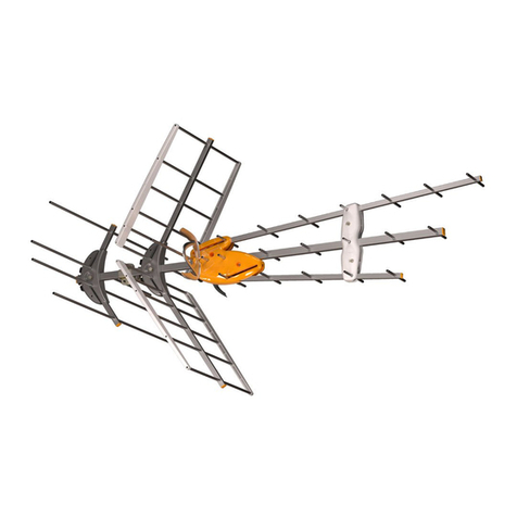
7 element Yagi UHF antenna (directional) with Microstrip technology (EU
patent) and VHF telescopic rods. Televes’ Exclusive Boss-Tech Amplier
Technology is the heart of our intelligent antenna, and it is activated by the
powering antenna (PSU included), so the antenna automatically adjusts itself
to deliver the optimum output signal level.
BOSS-Tech can also be powered using a battery or DC source (12V ) and
a power injector.
Dual Boss-Tech ampliers are built into the DiNova Antenna so VHF and UHF
bands are independently analysed and regulated in order to provide an
optimum balanced output signal level.
Operates in passive mode (no power) If desired or in case power is temporarily
interrupted from the power supply to the antenna. Televes recommends
powering our antennas for optimum performance in most installations.
Specially designed for DTT reception (rejects LTE/5G too). The DINOVA
antenna receives available digital and HD local programming in your area.
UV resistant protective plastic radome housing ideal to withstand adverse
climate conditions (moisture, water, wind, extreme heat, etc).
Compact, durable and unobstrusive design provides low visual impact. May be
installed on balconies, in attics or under eaves on single- family or multi-family
structures if line of site to the TV station transmitter(s) is obtainable.
Weather resistant automotive grade VHF elements for enhanced reception.
Easy installation with its built-in heavy duty mounting clamp.
Antena UHF Yagi de 7 elementos (direccional) con tecnología Microstrip (patente
EU) y varillas telescópicas (VHF). Su tecnología BOSS-Tech la convierte en
inteligente, se activa alimentando la antena (alimentación incluida), de forma
que la antena se ajusta automáticamente para dar siempre el mejor nivel de salida.
El BOSS-Tech puede alimentarse mediante una batería u otra fuente de
continua (12V ) y un inyector de corriente.
La antena incluye dos dispositivos BOSS de forma que las bandas de VHF y UHF
son analizadas y reguladas independientemente, de cara a proporcionar un
nivel de salida óptimo y equilibrado.
También se puede usar en modo pasivo (sin alimentar), cuando el nivel de señal
recibido en la zona es suciente.
Diseñada especialmente para la recepción de la Televisión Digital Terrestre
y preparada para rechazar las interferencias de la telefonía móvil. La antena
DINOVA recibe toda la programación digital y en HD disponible en su zona.
Protegida por un domo de plástico resistente a las radiaciones UV que la hace
ideal para ambientes climatológicos adversos (humedad, agua, viento, altas
temperaturas, etc.).
Compacta y con un diseño discreto de bajo impacto visual que la hace ideal para
su instalación en balcones y viviendas unifamiliares.
Para mejorar la recepción de VHF en condiciones de recepción difíciles, la
antena incorpora elementos extensibles inspirados en el sector de la automoción.
Fácil instalación gracias a la robusta abrazadera incorporada.
Troubleshooting / Resolución de problemas
Issue / Problema Possible Cause / Posible causa Solutions / Solución
Non functioning.
Funcionamiento incorrecto o
no funcionamiento.
Is unit plugged into working outlet?
¿Hay tensión de red?
Check electrical installation.
Revisar la instalación eléctrica.
No picture or sound.
No hay imagen ni sonido.
Is the TV tuned to an actual existing channel?
¿Es correcto el programa del receptor?
Tune the TV set to an existing local TV channel.
Programar el canal correctamente en su televisor.
Check installation cable and connectors for short circuit conditions.
Revisar la instalación de cable y conectores por si hubiese un cortocircuito.
Check DC voltage at the PSU’s antenna connector.
Comprobar que hay tensión continua en la entrada de antena de la fuente de alimentación.
Poor picture quality.
Mala calidad de imagen.
Is there a good line of sight to the transmitter?
¿Hay obstáculos entre la antena y el reemisor?
Remove obstacles and/or reassess antenna location.
Eliminar los obstáculos y/o reconsiderar el emplazamiento de la antena.
Adjust direction of antenna.
Reorientar la antena.
Safety Instructions:
LIGHTNING PROTECTION
If installed outdoors, be sure the antenna system is grounded so as to provide
protection against voltage surges and built-up static charges. Section 810 of the
National Electrical Code ANSI/NFPA70, or CSA C22.1 sections 10, 16, and 54, of the
Canadian Electrical Code, provide information with respect to proper grounding
of the mast and supporting structure, grounding of the antenna lead-in wire to
an antenna discharge unit, size of grounding conductors, location of antenna-
discharge unit, connection to grounding electrodes, and requirements for the
grounding electrode (see gure and instructions).
Mount the lightning arrestor or 75 ohm coaxial grounding block as close as possible
to where the 75 ohm coaxial cable downlead enters the house.
The ground wires for both the mast and the downlead should be copper or
aluminum wire, number eight (8) or larger.
The downlead wire from the antenna to the lightning arrestor and the mast ground
wire should be secured to the house, spaced from four (4) to six (6) feet apart.
In the case of a “ground up”antenna installation it may not be necessary to ground
the mast if the mast extends four or more feet in the earth. Consult a licensed
electrician for the proper depth in your location.
WARNINGS
To prevent re or shock hazard, do not expose the included power supply to rain
or moisture.
Installation of o-air antennas near power lines is dangerous. For your safety, follow
the installation instructions.
Any alteration or modication to the product or usage not in accordance with
product instructions voids the warranty.
Antenna Lead
in Wire
Example of antenna grounding as per
National Electrical Code, ANSI/NFPA 70
NEC - National Electrical Code
Ground
clamp
Electric Service
Equipment
Ground clamps
Power service Grounding Electrode System
(NEC Art 250, Part H)
Antenna Discharge Unit
(NEC Section 810-20)
(May substitute a 75 ohm
Coax Grounding Block)
Grounding Conductors
(NEC Section 810-21)
Instrucciones de seguridad:
PROTECCIÓN CONTRA RAYOS/DESCARGAS
Si la instalación es exterior, asegúrese de que el sistema esté conectado a tierra para la
protección contra descargas eléctricas exteriores y descargas de estática interiores. La
sección 810 del Código Eléctrico Nacional ANSI/NFPA70, o CSA C22.1 secciones 10, 16,
y 54, del Código Eléctrico Canadiense, proporcionan información respecto a la puesta
a tierra del mástil y de la estructura de soporte, puesta a tierra del cableado de la ante-
na, interconexión de cables hacia unidades de descarga, tamaño de las líneas de tierra,
ubicación de las unidades de descarga, conexión hacia electrodos de puesta a tierra y
requerimientos de estos electrodos (ver gura e instrucciones).
Montar una unidad de descarga o carga coaxial de 75 Ohms tan cerca de la entrada del
cable coaxial en la vivienda como sea posible.
Utilizar alambre de cobre o aluminio de calibre ocho (8) o superior para las líneas de
tierra tanto del mástil como del cable de bajada.
El cable de bajada de la antena a la unidad de descarga y la línea de descarga del mástil
deben estar asegurados a la casa, separados entre si de 1,2 a 1,8 m.
Cuando el mástil se instala directamente sobre tierra alcanzando una profundidad de
cuatro (4) o más pies en el terreno puede no ser necesaria una línea de masa. Consulte
a un instalador especializado para conocer el dato exacto correspondiente a su zona.
ADVERTENCIAS
Para reducir el riesgo de fuego o choque eléctrico, no exponer la fuente de alimentación
a la lluvia o a la humedad.
Es peligroso instalar antenas terrestres cerca de líneas de alta tensión. Extreme la pre-
caución y siga las instrucciones.
La modicación o alteración del producto o su utilización para un n distinto a aquel
para el que fue diseñado invalida toda garantía.
Cable de entrada
desde la antena
Ejemplo de puesta a tierra de una antena
de acuerdo al Código Eléctrico Nacional, ANSI/NFPA 70
NEC - Código Eléctrico Nacional
Abrazadera de
puesta a tierra
Equipo de
servicio
eléctrico
Abrazaderas de puesta a tierra
Sistema de electrodos para puesta a tierra
del servicio eléctrico (NEC Art. 250, Parte H)
Unidad de descarga
para antena
(NEC Sección 810-20)
Conductores de
puesta a tierra
(NEC Sección 810-21)
This equipment has been tested and found to comply with the limits for a Class
B digital device, pursuant to part 15 of the FCC Rules. These limits are designed
to provide reasonable protection against harmful interference in a residential
installation. This equipment generates, uses and can radiate radio frequency
energy and, if not installed and used in accordance with the instructions, may
cause harmful interference to radio communications. However, there is no
guarantee that interference will not occur in a particular installation. If this
equipment does cause harmful interference to radio or television reception,
which can be determined by turning the equipment o and on, the user is
encouraged to try to correct the interference by one or more of the following
measures:
- Reorient or relocate the receiving antenna.
- Increase the separation between the equipment and receiver.
- Connect the equipment into an outlet on a circuit dierent from that to which
the receiver is connected.
- Consult the dealer or an experienced radio/TV technician for help.
2022 © Copyright, Televés S.A.U.
YELLOW
GREENVIOLET
BLUE LIGHT
GREEN
RED
UHF
YELLOW
GREEN
LIGHT
GREEN
High VHF
YELLOW
GREENVIOLET
BLUE LIGHT
GREEN
RED
UHF
YELLOW
GREEN
LIGHT
GREEN
High VHF
YELLOW
GREENVIOLET
BLUE LIGHT
GREEN
RED
UHF
YELLOW
GREEN
LIGHT
GREEN
High VHF
UHF High-VHF Low-VHF
Specications Características Active / Activo
Operating band Banda de trabajo MHz
Low VHF
55 - 88
CH2 - CH6
High VHF
174 - 216
CH7 - CH13
UHF
470 - 608
CH14 - CH36
Gain Ganancia dBi 16 29 34
Noise gure (typ.) Figura ruido (tip.) dB 3 2.5
Output level Nivel salida dBmV
(DIN45004B) Self regulated / Autorregulable
Power supply Alimentación V12
Max. current Corriente máxima mA 70
Protection level Indice de protección IP 53
Weight Peso lb / g 3.6 / 1660
Dimensions Dimensiones in / mm 16.2” x 31.3” x 2.8” / 412 x 795 x 73
Wind load Carga al viento N70 (@ 80 Miles/h) / (@ 130 Km/h)
96 (@ 93 Miles/h) / (@ 150 Km/h)
Limited Warranty
Televés S.A. warrants this product against any defects in materials or workmanship within 90 (ninety) days from
the date of purchase. No warranty claim will be honored unless at the time the claim is made, you present proof of
purchase to an authorizedTelevés dealer (if unknown, please contact Televes USA LLC, Norfolk Tech Center 16596 E.
2nd Avenue Aurora, CO 80011 (USA) - Tel: (720) 379-3748.
Televés (at its sole discretion) will either repair or replace the defective product at no charge. This warranty covers
parts, but does not cover any costs incurred in removal, shipping or reinstallation of the product. This limited warranty
does not apply if the product is damaged, deteriorates, malfunctions or fails from misuse, improper installation,
abuse, neglect, accident, tampering, modication of the product as originally manufactured by Televés, usage not
in accordance with product instructions or acts of nature such as damage caused by wind, lightning, ice or corrosive
environments such as salt spray and acid rain.
The 90 day warranty is provided on the condition that the equipment is properly delivered with all handling and
freight charges prepaid to your Televés dealer for return to our factory for repair or replacement. Televés will arrange
for the replacement or repair and return without charge the product which failed due to defective material or
workmanship.
Televés will not assume any liabilities for any other warranties, express or implied, made by any other person.
All other warranties whether express, implied or statutory including warranties of tness for a particular purpose and
merchantability are limited to the 90-day period of this warranty.
The foregoing shall be the sole and exclusive remedy of any person, whether in contract, tort or otherwise, and
Televés shall not be liable for incidental or consequential damage or commercial loss, or from any other loss or
damage except as set forth above.
Some states do not allow limitations on how long an implied warranty lasts, or the exclusion of limitation of
incidental or consequential damages, so the above limitations or exclusions may not apply to you.
This warranty gives you specic legal rights and you may also have other rights which vary from state to state.
Televes and DINOVA are registered trademarks of Televés S.A. All trademarks are property of their respective owners.
Garantía Limitada
Televés S.A. garantiza que este producto está libre de cualquier defecto en los materiales o fabricación del mismo durante
90 (noventa) días a partir de la fecha de compra. No se aceptarán reclamaciones salvo que en el momento de producirse
se presente prueba de compra a un distribuidor autorizado de Televés S.A. (si lo desconoce, por favor contacte con Televés
USA LLC, Norfolk Tech Center 16596 E. 2nd Avenue Aurora, CO 80011 (USA) - Tel: (720) 379-3748).
Televés S.A. (a su discreción) reparará o reemplazara el producto defectuoso sin costo. Esta garantía cubre las piezas,
pero no cubre los costes relacionados con el desmontaje, envío o reinstalación del producto. Esta garantía limitada no es
aplicable si el producto está dañado, deteriorado o falla debido a un mal uso, instalación inadecuada, abuso, negligencia,
accidente, alteración, modicación del producto originalmente fabricado por Televés S.A., uso no acorde con las instruc-
ciones del producto o actos de la naturaleza tales como el daño causado por el viento, relámpagos, hielo o ambientes
corrosivos tales como la sal o lluvia ácida.
La garantía de 90 días se otorga bajo condición que el equipo sea entregado en forma adecuada a su distribuidor auto-
rizado de Televés S.A. con gastos de envío prepagados para su devolución a fábrica para su reparación o reemplazo. Un
distribuidor autorizado de Televés S.A. se encargará de la sustitución o reparación y devolución sin costo del producto que
haya fallado debido a material o mano de obra defectuosos.
Televés S.A. no asumirá responsabilidad alguna por cualquier otra garantía, expresa o implícita, realizada por cualquier
persona.
Todas las otras garantías, independientemente de si son expresas, implícitas o establecidas por la ley, incluyendo las
garantías acerca de su idoneidad para un propósito en especíco y su comercialización están limitadas al período de 90
días de esta garantía.
Lo anterior será la única reparación exclusiva para cualquier persona, sea a través de contrato, responsabilidad extra
contractual o de naturaleza distinta, y Televés S.A. no será responsable por daños fortuitos o consecuentes ni pérdida
comercial, o cualquier otra pérdida o daño excepto los establecidos con anterioridad.
Algunos estados no permiten limitaciones respecto a la duración de una garantía implícita, o la exclusión de limitaciones
por daños fortuitos o consecuentes, así que podría ser que las limitaciones o exclusiones mencionadas anteriormente no
sean aplicables en su caso.
Esta garantía establece sus derechos legales especícos y usted podría también tener otros derechos que variarán de
estado a estado.
Televés y DINOVA son marcas registradas de Televés S.A. Todas las marcas son propiedad de sus respectivos propietarios.
Televes USA LLC. Norfolk Tech Center 16596 E. 2nd Avenue Aurora, CO 80011 televes.usa@televes.com www.televes.com

This manual suits for next models

2

Other Televes Antenna manuals

Televes 108320 User manual

Televes

Televes 108320 User manual

Televes DATBOSSLR 149783 User manual

Televes

Televes DATBOSSLR 149783 User manual

Televes Omni-Nova Boss User manual

Televes

Televes Omni-Nova Boss User manual

Televes DATBOSS 149921 User manual

Televes

Televes DATBOSS 149921 User manual

Televes DATBOSS MATV 149983 User manual

Televes

Televes DATBOSS MATV 149983 User manual

Televes INNOVA BOSS MIX User manual

Televes

Televes INNOVA BOSS MIX User manual

Televes 534040 User manual

Televes

Televes 534040 User manual

Televes Omni-Nova Boss User manual

Televes

Televes Omni-Nova Boss User manual

Televes Ellipse User manual

Televes

Televes Ellipse User manual

Televes Evoca 130990 User manual

Televes

Televes Evoca 130990 User manual

Televes TRINOVA BOSS User manual

Televes

Televes TRINOVA BOSS User manual

Televes Dinova Boss Series User manual

Televes

Televes Dinova Boss Series User manual

Televes DAT BOSS MIX User manual

Televes

Televes DAT BOSS MIX User manual

Televes CAMPNOVA BOSS User manual

Televes

Televes CAMPNOVA BOSS User manual

Televes 4G NOVA User manual

Televes

Televes 4G NOVA User manual

Televes omni-nova User manual

Televes

Televes omni-nova User manual

Televes DAT HD Boss 790 User manual

Televes

Televes DAT HD Boss 790 User manual

Televes DATBOSSMIX 149484 User manual

Televes

Televes DATBOSSMIX 149484 User manual

Televes Offset 830 Series User manual

Televes

Televes Offset 830 Series User manual

Televes evoca 130990 Parts list manual

Televes

Televes evoca 130990 Parts list manual

Televes T.0X Series User manual

Televes

Televes T.0X Series User manual

Televes MATV User manual

Televes

Televes MATV User manual

Televes K20 Series User manual

Televes

Televes K20 Series User manual

Televes 144110 User manual

Televes

Televes 144110 User manual

Popular Antenna manuals by other brands

Steren ANT-100 user manual

Steren

Steren ANT-100 user manual

EchoStar DISH 500+ installation instructions

EchoStar

EchoStar DISH 500+ installation instructions

KVH Industries TracVision HD11 Replacement instructions

KVH Industries

KVH Industries TracVision HD11 Replacement instructions

Diamond HF6FX instruction sheet

Diamond

Diamond HF6FX instruction sheet

Matchmaster 04MM-RP03 instruction manual

Matchmaster

Matchmaster 04MM-RP03 instruction manual

AEG AAN X1 Mounting

AEG

AEG AAN X1 Mounting

MFJ 1801 quick start guide

MFJ

MFJ 1801 quick start guide

Winegard YA7000C instruction manual

Winegard

Winegard YA7000C instruction manual

Optex iVision+ Connect IVPC-ANT Settings and setup guide

Optex

Optex iVision+ Connect IVPC-ANT Settings and setup guide

Ubiquiti AirFiber X AF-5G34-S45 quick start guide

Ubiquiti

Ubiquiti AirFiber X AF-5G34-S45 quick start guide

H3C ANT-2009Y manual

H3C

H3C ANT-2009Y manual

KVH Industries TracVision L3 owner's manual

KVH Industries

KVH Industries TracVision L3 owner's manual

Texas Instruments Tag-it RI-K01-320A reference guide

Texas Instruments

Texas Instruments Tag-it RI-K01-320A reference guide

Alpha Antenna Alpha Loop operating manual

Alpha Antenna

Alpha Antenna Alpha Loop operating manual

1 BY ONE OUS00-0560 manual

1 BY ONE

1 BY ONE OUS00-0560 manual

DX Engineering HEXXAGONAL BEAM Mark 2 instructions

DX Engineering

DX Engineering HEXXAGONAL BEAM Mark 2 instructions

A.H. Systems AK-40G Operation manual

A.H. Systems

A.H. Systems AK-40G Operation manual

Besto BOWTIE user manual

Besto

Besto BOWTIE user manual

manuals.online logo
manuals.online logoBrands
  • About & Mission
  • Contact us
  • Privacy Policy
  • Terms and Conditions

Copyright 2025 Manuals.Online. All Rights Reserved.