manuals.online logo
Brands
  1. Home
  2. •
  3. Brands
  4. •
  5. Tennant
  6. •
  7. Scrubber
  8. •
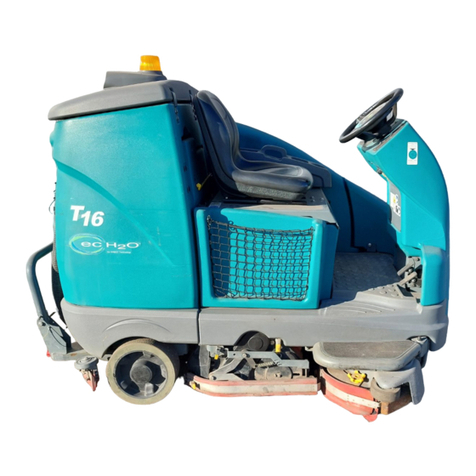
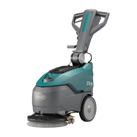
  9. Tennant T16 Training manual

Tennant T16 Training manual

IB 9008460 (08- 2015) 1
INSTRUCTION BULLETIN
No. 9008460
Machine: T16
Published: 08- 2015
Rev. 02
NOTE: DO NOT DISCARD the Parts List from the Instruction Bulletin. Place the
Parts List in the appropriate place in the machine manual for future
reference. Retaining the Parts List will make it easier to reorder
individual parts and will save the cost of ordering an entire kit.
NOTE: Numbers in parenthesis ( ) are reference numbers for parts listed in Bill of Materials.
Installation instructions for kit number 9008139
SYNOPSIS:
This kit contains the parts needed to install a strobe light / backup alarm kit on T16 machines.
Please follow step-by-step instructions.
SPECIAL TOOLS / CONSIDERATIONS: NONE
(Estimated time to complete: 1.5 hours)
PROTECT THE ENVIRONMENT
Please dispose of packaging materials, used machine components
such as batteries and fluids in an environmentally safe way according
to local waste disposal regulations.
Always remember to recycle.
PREPARATION:
1. Park the machine on a clean level surface,
turn off the machine, and remove the key.
FOR SAFETY: Before leaving or servicing
machine, stop on level surface, turn off
machine, and remove key.
2. Disconnect the battery cables from the
batteries.
WARNING: Always disconnect battery
cables from machine before working on
electrical components.
INSTALLATION:
1. Remove the plugs from the recovery tank
cover and discard both plugs. (Fig. 1)
FIG. 1
2. Completely open the recovery tank cover and
lock the cover open.
IB 9008460 (08- 2015)2
Use dimple to center
2” (50 mm) hole saw
between two holes
Use dimple to center
1” (25 mm) drill bit
between two holes
FIG. 2
NOTE: Use the dimple located in the recovery
tank cover to center the hole saw on the cover.
3. Drill a 1” (25 mm) hole through the recovery
tankcover.(Fig.2/Fig.3)
FIG. 3
4. Close the recovery tank cover.
NOTE: Use the dimple centered between the two
holes in the recovery tank cover to center the hole
saw on the cover.(Fig. 3)
5. Use a 2” (50 mm) hole saw to cut a hole
through the top of the recovery tank cover. Do
Not cut into the bottom of the recovery tank
cover. (Fig. 2)
6. Use two M5 pan screws (14), two flat washers
(15), and two M5 hex nuts to install the light
(1) onto the light module base (2). (Fig. 4)
1
2
15
16
16
15
14
14
FIG. 4
IB 9008460 (08- 2015) 3
7. Use a cable tie (5), a hex screw (6), and a flat
washer (7) to secure the backup alarm (4) to
the light module base (2). (Fig. 5)
2
4
5
6
7
8
9
FIG. 5
8. Use a cable tie (9) to secure one 2.5 Amp
circuit breaker (8) to the light module base (2).
(Fig. 5)
9. Use two M8 hex screws (17) to install the light
module base (2) and module base gasket (3)
onto the recovery tank cover. (Fig. 6)
2
3
10
11
17
17
FIG. 6
10. Route the end of the alarm / light wire harness
(10) with the single connector down through
the module base (2), module base gasket (3),
the 2” (50 mm) hole in the recovery tank
cover, and out the 1” (25 mm) hole in the
recovery tank cover. (Fig. 6)
11. Slide the rubber grommet (11) onto the alarm
/ light wire harness (10) and insert the
grommet into the 1” (25 mm) hole in the
recovery tank cover. (Fig. 6)
IB 9008460 (08- 2015)4
12. Route the alarm / light wire harness (10)
down behind the operator seat and connect
the alarm / light wire harness to the main
wire harness connector located behind the
operator seat. (Fig. 8 / Fig. 9)
13. Connect the alarm / light wire harness (10) to
the light (1), backup alarm (4), and the 2.5
Amp circuit breaker (8). (Fig. 8 / Fig. 9)
14. Plug the 36VDC relay (12) into the alarm /
light wire harness (10). (Fig. 7 / Fig. 8)
FIG. 7
FIG. 8
IB 9008460 (08- 2015) 5
FIG. 9 - Main Wire Harness
IB 9008460 (08- 2015)6
FIG. 10 - Schematic
IB 9008460 (08- 2015) 7
15. Use two pan screws (20) to install each LED
light assembly (19) onto the light module
cover (18). (Fig. 11)
18
19
20
FIG. 11
16. Connect the alarm / light wire harness (10)
to both LED light assemblies (19). (Fig. 8 /
Fig. 10)
17. Use two pan screws (20) to install the light
module cover (18) onto the rest of the light /
alarm assembly. (Fig. 17)
18. Remove the hardware holding the left console
panel to the front shroud and set the
hardware aside. (Fig. 12)
19. Carefully pull the left console panel from the
front shroud. Take care to not break any wire
connections when pulling the panel from the
shroud. (Fig. 12)
20. Remove the hole plug from the left console
panel and discard the plug. Refer to Fig. 12.
21. Insert the switch (21) into the left console
panel. (Fig. 12)
22. Connect the main wire harness to the switch
(21). (Fig. 9)
23. Reinstall the left console panel onto the front
shroud. (Fig. 12)
Remove and discard
hole plug. Install
switch (21) into
switch location
Set all hardware aside
Left console panel
Front shroud
FIG. 12
IB 9008460 (08- 2015)8
24. Remove the hardware holding the electrical
panel to the machine. Set the hardware aside.
(Fig. 13)
FIG. 13
25. Carefully remove the electrical panel from the
machine. Take care to not break any cable /
wire connections when removing the panel.
26. Remove the blanks from the CB15 and CB11
locations on the electrical panel. (Fig, 14)
FIG. 14
27. Install a 2.5- Amp circuit breaker (8) and
circuit breaker boot (22) into electrical panel
CB15 location. (Fig, 15)
FIG. 15
28. Install a 15- Amp circuit breaker (25) and
circuit breaker boot (22) into electrical panel
CB15 location. (Fig, 11)
29. Connect the main wire harness to the 2.5
Amp circuit breaker (8) and 15- Amp circuit
breaker (25) installed in the previous steps.
(Fig. 15 / Fig. 16)
30. Reinstall the electrical panel onto the
machine.
31. Reconnect the battery cables to the batteries.
32. Start and test the machine. Position the
operating light / hazard light switch to the ON
position and operate the machine in both the
forward and reverse directions. The strobe
light and red LED taillights should function
when the lights are turned on and the white
reverse LED lights and alarm should function
when the machine is in reverse.
FIG. 16
IB 9008460 (08- 2015) 9
1
2
3
45
6
7
89
10
11
12 13
14
15
16
17
18
19
20
20
FRONT
21
FIG. 17
IB 9008460 (08- 2015)10
Bill Of Materials For Light Kit, Strobe, CI [T16] - 9008139
Ref.
Tennant
Part No. Description Qty.
o9008139 Light Kit, Strobe, CI [T16] 1
Y1 1017250 Light, Strobe, Amb, 12- 48VDC 1
Y2 1059938 Base, Module, Light 1
Y3 1063263 Gasket, Base, Module 1
Y4 1058694 Alarm, Backup, 12- 48VDC, Adj 1
Y549263 )Tie, Cable, Nyl, 11.4L .19W 3.0 Max D 1
Y6 19315 Screw, Hex, .25- 20 X 0.50, G5 1
Y7 32483 Washer, Flat, 0.25, SAE 1
Y8 1064184 Circuit Breaker, 02.5A, Resettable 2
Y9 49266 Tie, Cable, Nyl, 07.3L .19W 1.8 Max D 1
Y10 1056979 )Harness, Wire, Alarm / Light [T16] 1
Y11 10632- 18 Grommet, Rbr, 0.69ID, F/1.0H, .25 Matl 1
Y12 398526 Relay, 36VDC, 005A, SPDT NO [Greenwich] 1
Y13 1020341 Screw, Hex, M8 X 1.25 X 20, SS, SEMS 1
Y14 06933 Screw, Pan, Phl, M5 X 0.80 X 16, 4.8 2
Y15 19066 )Washer, Flat, 0.25B 0.56D .05, PL, 10 2
Y16 06549 Nut, Hex, Lock, M5 X 0.80, NL 2
Y17 1020341 Screw, Hex, M8 X 1.25 X 20, SS, SEMS 1
Y18 1062106 Cover, Module, Light 1
Y19 1059342 Light Assy, LED 1
Y20 222267 )Screw, Pan, Phl, 06- 20 X 0.50, FMG/AB 6
Y21 377084 Switch, Rocker, Prgrsv 1
Y22 1064191 Boot, Circuit Breaker 2
Y23 55272 Terminal, Bullet, Mal, .157D, 12Ga 2
Y24 C080140 Sleeve, Vyl, Flex, .23ID, Bulk (6 in) 1
Y25 1064188 Circuit Breaker, 15.0a, Resettable 1
TENNANT COMPANY
P. O. Box 1452
Minneapolis, MN 55440-1452

Other manuals for T16

7

Other Tennant Scrubber manuals

Tennant t500 Operating and installation instructions
Tennant

Tennant t500 Operating and installation instructions

Tennant T16 Operating and installation instructions

Tennant

Tennant T16 Operating and installation instructions

Tennant t500e User manual

Tennant

Tennant t500e User manual

Tennant T20 LPG Training manual

Tennant

Tennant T20 LPG Training manual

Tennant M17 Series User manual

Tennant

Tennant M17 Series User manual

Tennant T981 User manual

Tennant

Tennant T981 User manual

Tennant CS16 User manual

Tennant

Tennant CS16 User manual

Tennant 8410 User manual

Tennant

Tennant 8410 User manual

Tennant T15 Operating and installation instructions

Tennant

Tennant T15 Operating and installation instructions

Tennant 265XP User manual

Tennant

Tennant 265XP User manual

Tennant T7 User manual

Tennant

Tennant T7 User manual

Tennant T981 User manual

Tennant

Tennant T981 User manual

Tennant T5 User manual

Tennant

Tennant T5 User manual

Tennant 7300 User manual

Tennant

Tennant 7300 User manual

Tennant IRIS T300 User manual

Tennant

Tennant IRIS T300 User manual

Tennant 5680 User manual

Tennant

Tennant 5680 User manual
Tennant T12 Training manual

Tennant

Tennant T12 Training manual

Tennant T1 User manual

Tennant

Tennant T1 User manual

Tennant CS16 User manual

Tennant

Tennant CS16 User manual

Tennant Nobles T350 User manual

Tennant

Tennant Nobles T350 User manual

Tennant T300e User manual

Tennant

Tennant T300e User manual

Tennant 5400 Product manual

Tennant

Tennant 5400 Product manual

Tennant 8300 User manual

Tennant

Tennant 8300 User manual

Tennant 5700XP User manual

Tennant

Tennant 5700XP User manual

Popular Scrubber manuals by other brands

COMAC SIMPLA 500E Use and maintenance manual

COMAC

COMAC SIMPLA 500E Use and maintenance manual

Clarke Focus II Mid-Size Autoscrubber Disc 26 Operator's manual

Clarke

Clarke Focus II Mid-Size Autoscrubber Disc 26 Operator's manual

cimex Cyclone CR38 User instructions

cimex

cimex Cyclone CR38 User instructions

MistAway FumeAway FA200 user manual

MistAway

MistAway FumeAway FA200 user manual

Electrolux Professional W575S Service manual

Electrolux Professional

Electrolux Professional W575S Service manual

Nilfisk-Advance Captor 4300 Mechanical repair service manual

Nilfisk-Advance

Nilfisk-Advance Captor 4300 Mechanical repair service manual

Wetrok Duomatic Series operating instructions

Wetrok

Wetrok Duomatic Series operating instructions

Festool TURBO II M 8 WP R1 operating manual

Festool

Festool TURBO II M 8 WP R1 operating manual

Nederman MagnaTrack HS Original user manual

Nederman

Nederman MagnaTrack HS Original user manual

Windsor Dominator NMWU2250H operating instructions

Windsor

Windsor Dominator NMWU2250H operating instructions

Esco ENVIROSAFE user manual

Esco

Esco ENVIROSAFE user manual

Livington PRIME PRO kit manual

Livington

Livington PRIME PRO kit manual

COMAC Vispa 35E Use and maintenance manual

COMAC

COMAC Vispa 35E Use and maintenance manual

ABATEMENT PREDATOR  PRED750 instruction manual

ABATEMENT

ABATEMENT PREDATOR PRED750 instruction manual

Coopers 10946 Instructions for use

Coopers

Coopers 10946 Instructions for use

ulsonix TOPCLEAN 1200PRO+ user manual

ulsonix

ulsonix TOPCLEAN 1200PRO+ user manual

Castex PX-1000 Operator and parts manual

Castex

Castex PX-1000 Operator and parts manual

Vax VCW-05 user guide

Vax

Vax VCW-05 user guide

manuals.online logo
manuals.online logoBrands
  • About & Mission
  • Contact us
  • Privacy Policy
  • Terms and Conditions

Copyright 2025 Manuals.Online. All Rights Reserved.