Teo 4104 User manual

Software Version 06.04.18, Document #13-280131 Rev. J
February 2014
Teo Technologies, Inc.
11609 49th Place West
Mukilteo, WA 98275-4255
(800) 524-0024 (425) 349-1000
Fax (425) 349-1010
www.teotech.com
I
IP
P
P
Ph
ho
on
ne
e
4
41
10
04
4
I
In
ns
st
ta
al
ll
la
at
ti
io
on
n
I
In
ns
st
tr
ru
uc
ct
ti
io
on
ns
s

Teo IP Phone 4104 Installation Instructions
Page 2 13-280131 Rev. J
© 2014 Teo Technologies Inc. All rights reserved.

13-280131 Rev. J Page 3
Introduction ................................................................................................................................. 5
General Features .................................................................................................................. 5
Controls and Indicators ........................................................................................................ 6
Installation ................................................................................................................................... 9
Connecting the Phone .......................................................................................................... 9
Routing the Cords............................................................................................................... 10
Adjusting the Telephone Angle ......................................................................................... 11
Wall Mounting .................................................................................................................... 12
Labeling Keys...................................................................................................................... 13
Configure the Set................................................................................................................ 14
Installation Options................................................................................................................... 19
Installation Options Menu.................................................................................................. 19
IP Addresses ....................................................................................................................... 20
SIP Configuration................................................................................................................ 25
Quality of Service ............................................................................................................... 30
Configuring Keys ................................................................................................................ 31
Configuring the Speakerphone.......................................................................................... 40
Call Timeout Options.......................................................................................................... 41
Installation PIN.................................................................................................................... 42
Reset to Factory Default Settings ...................................................................................... 43
Updates ............................................................................................................................... 44
PC Port................................................................................................................................. 47
Security Options ................................................................................................................. 47
Viewing the Error Log ........................................................................................................ 48
Administration Options ............................................................................................................ 49
Administration Options Menu ........................................................................................... 49
Local Inspect ....................................................................................................................... 50
Version ................................................................................................................................ 51
Test...................................................................................................................................... 52
Diagnostic Displays ............................................................................................................ 54
Restarting the Phone .......................................................................................................... 56
Troubleshooting ........................................................................................................................ 57
Power-up & Connection Troubleshooting......................................................................... 57
Call Control Troubleshooting............................................................................................. 58
Diagnostic Troubleshooting............................................................................................... 59
Appendix A Setup Menu Tree ............................................................................................. 63
Appendix B Service and Warranty ...................................................................................... 71
Appendix C Specifications................................................................................................... 73
Appendix D Regulatory Statements .................................................................................... 75
C
C
Co
o
on
n
nt
t
te
e
en
n
nt
t
ts
s
s

Teo IP Phone 4104 Installation Instructions
Page 4 13-280131 Rev. J

13-280131 Rev. J Page 5
For operation instructions and user setup options, please
refer to the IP Phone 4104 User Guide, doc. #14-280205.
G
Ge
en
ne
er
ra
al
l
F
Fe
ea
at
tu
ur
re
es
s
The Teo Model 4104 IP Phone is an easy to use multiline terminal that provides
sophisticated services over managed IP networks running the Session Initiation Protocol
(SIP). The telephone includes a built-in 10/100BaseT switch to allow daisy-chain connection
of a PC workstation without additional equipment.
Features of the 4104 include:
•
100-entry Call Log for Unanswered,
Answered, and Outgoing Calls
•Call Timer
•Last Number Redial
•Speed Dial
•Pre-Dialing
•Direct Station Select
•36-entry Call Directory
•Voice Mail Access Key
•Message Waiting Indication
•Backlit Graphic LCD Display
•
Ringing Control for Shared Lines
•Flexible Ringing Options
•Desktop or Wall Mounting
•Integrated Speakerphone
•Call Monitoring
•Handset or Headset Operation
•Headset Activation Key
•Dedicated Headset Jack
•Integrated 10/100BaseT Switch
•802.3af Power over Ethernet
or Local Power
Various features may not be available with some SIP services.
I
I
In
n
nt
t
tr
r
ro
o
od
d
du
u
uc
c
ct
t
ti
i
io
o
on
n
n

Teo IP Phone 4104 Installation Instructions
Page 6 13-280131 Rev. J
C
Co
on
nt
tr
ro
ol
ls
s
a
an
nd
d
I
In
nd
di
ic
ca
at
to
or
rs
s
1) Display – shows the call state, caller ID, dialed digits, network call control messages,
elapsed time during calls, the date and time of day, and softkey options.
The viewing angle is primarily set by changing the base/mounting bracket angle (page
11). Display contrast can be adjusted by a menu selection.
2) Line Keys – used for Primary Line Appearances.
Line Appearance Key Indicator Line State
OFF Idle (On-Hook)
Steady Green In Use (Off-Hook)
Winking Green On Hold
Flashing Green Ringing
3) Multifunction Keys – used for Additional Line Appearance, Direct Station Selection/
Busy Lamp Field (DSS/BLF), Feature, or Speed Dial keys. The optional 8030X Button
Expansion Module provides 30 additional multifunction keys.
Red and green indicators on the keys show line appearance, DSS/BLF and feature
status.

Introduction
13-280131 Rev. J Page 7
DSS/BLF Key Indicator Monitored Station State
OFF Available (On-Hook)
Steady Red /Green Other Presence State* (On-Hook)
Steady RedOn The Phone (Off Hook)
Flashing Green Ringing
* Note: If your phone is connected to a Teo UC System, steady red/green is used to indicate
Busy, Away, Not Available, Do Not Disturb, On Holiday, On Vacation, After Hours, or Call
Forward presence states.
Feature Key Indicator Feature State
OFF Deactivated
Steady Red Activated
4) Softkeys – select the function displayed above the key on the bottom line of the display.
5) Navigation (Arrow) Keys – navigate within menus. In editing modes, thekey moves
the cursor one position to the right and thekey moves the cursor one position to the
left. The and keys are used to shift between pages on multi-page screens. The OK
key exits the current menu, saves any changes made, and returns to the previous menu
options.
6) Message Waiting Indicator – a bright red indicator is lit when messages are waiting,
controlled by the network.
7) VOICE MAIL Key – accesses network voice mail services.
8) MENU Key – enters and exits Setup Mode.
9) LOG Key – displays Call Log options.
10) DIRECTORY Key – displays the Call Directory.
11) INFO Key – displays version and configuration information about the 4104 and installed
options.
12) MUTE Key – mutes the microphone when using the speakerphone or handset/headset.
A red indicator on the key is lit when mute is active.
13) SPEAKER Key – activates the speakerphone or Call Monitoring (if enabled by your
installer). A green indicator on the key is lit when the speakerphone or Call Monitoring
is in use.
14) HEADSET Key – activates the headset. A green indicator is lit when the headset is in
use.
15) VOLUME Key – adjusts the receiver/speaker volume when on a call; adjusts the ringer
volume when on-hook.
16) Dial Pad – dials telephone numbers, and sends DTMF tones to external equipment such
as voice mail systems. The dial pad is also used for text and number entry during setup.
17) Microphone – used for hands-free (speakerphone) calling; located under the right front
corner of the telephone.

Teo IP Phone 4104 Installation Instructions
Page 8 13-280131 Rev. J
18) Handset Jack – a jack on the underside of the telephone connects to the included
handset.
19) Headset Jack – a jack on the underside of the telephone connects to an optional
standard headset.
13-280131 Rev. J Page 9
C
Co
on
nn
ne
ec
ct
ti
in
ng
g
t
th
he
e
P
Ph
ho
on
ne
e
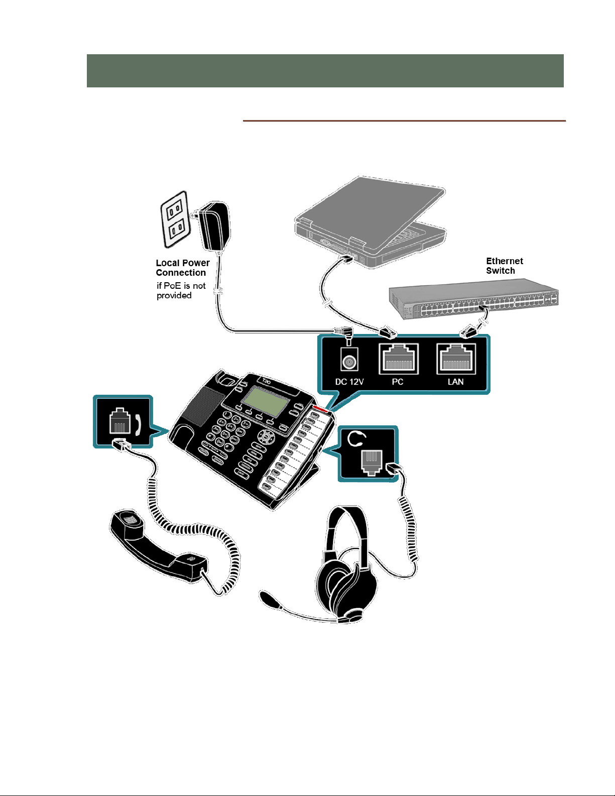
Connect the 4104 phone to power, LAN, WAN, and the handset or a headset as shown
below.
N
Ne
et
tw
wo
or
rk
k
C
Co
on
nn
ne
ec
ct
ti
io
on
n
Connect the LAN switch to the phone’s LAN jack using a Category 5 or better cable. If the
network switch provides 802.3af Power over Ethernet (PoE), a local power supply
connection is not needed.
I
I
In
n
ns
s
st
t
ta
a
al
l
ll
l
la
a
at
t
ti
i
io
o
on
n
n

Teo IP Phone 4104 Installation Instructions
Page 10 13-280131 Rev. J
P
PC
C
C
Co
on
nn
ne
ec
ct
ti
io
on
n
If you want to use a PC on the same network connection, connect the PC network interface
card to the phone's PC jack using a Category 5 or better cable.
H
Ha
an
nd
ds
se
et
t/
/H
He
ea
ad
ds
se
et
t
Plug the supplied handset into the Handset jack on the left side of the phone. Plug a
compatible headset into the Headset jack on the right side of the phone.
P
Po
ow
we
er
r
The 4104 is compatible with IEEE 802.3af power over Ethernet cabling, utilizing either
power over spare cable pairs (midspan power source) or phantom power (powered
switch/hub port). The phone provides an 802.3af PD Class 2 indication to the power
sourcing equipment and requires a maximum of 5 watts of power.
Power may also be provided by an optional local power supply (-PWR4 option,
Teo model 901054).
Connect power after all other connections are complete. If PoE is not provided,
plug the power supply barrel connector into the round DC 12V jack on the back of
the phone. Connect the power supply to a standard 100-240 VAC, 50-60 Hz power
outlet.
R
Ro
ou
ut
ti
in
ng
g
t
th
he
e
C
Co
or
rd
ds
s
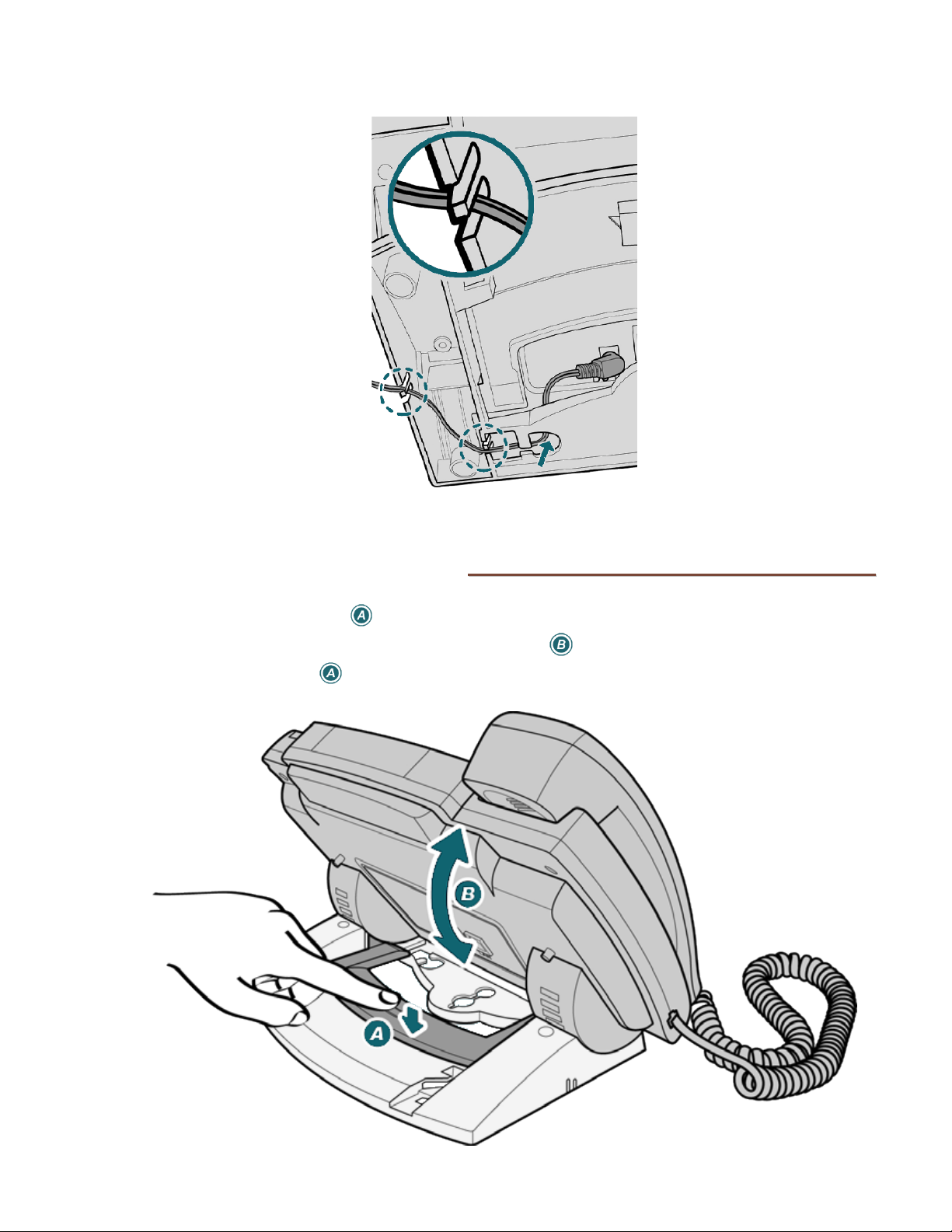
To place the phone on a desk or flat surface, properly route the cords to ensure
uninterrupted connections.
L
LA
AN
N
a
an
nd
d
P
PC
C
C
Co
or
rd
ds
s
Installation
13-280131 Rev. J Page 11
A
AC
C
P
Po
ow
we
er
r
A
Ad
da
ap
pt
te
er
r
C
Co
or
rd
d
A
Ad
dj
ju
us
st
ti
in
ng
g
t
th
he
e
T
Te
el
le
ep
ph
ho
on
ne
e
A
An
ng
gl
le
e
•Press down the tab to loosen the base lock.
•As you press the tab, rotate the phone body up or down a slot to adjust tilt.
•Release the tab to lock the base to a slot.

Teo IP Phone 4104 Installation Instructions
Page 12 13-280131 Rev. J
W
Wa
al
ll
l
M
Mo
ou
un
nt
ti
in
ng
g
To save space, you can directly hang the phone on a wall or wall plate. You need two
screws that will fit the keyhole slots.
Note: Wall mounting screws are not supplied with the phone.
•On the wall or a wall plate, drill two holes with a distance of 315/16 inches apart. If
drilling into drywall only, make sure to install an anchor system for the screws.
•Thread a screw into each hole with each head extending about 3/16 inch from the wall
or wall plate.
•Connect the AC power adapter, LAN and PC cords (pages 9-11)and route them to go
under the base.
•Adjust the base so it lays flat on the back of the phone.
•Fasten the base to the back of the phone with the supplied screws.
Installation
13-280131 Rev. J Page 13
•Align the phone’s keyhole slots with the screws and slide the phone downward to
secure it.
L
La
ab
be
el
li
in
ng
g
K
Ke
ey
ys
s
The 12 multifunction keys on the right side of the phone can be labeled with the telephone
number, feature name, speed dial party name, or other appropriate designation.
Remove the clear label cover by lifting the right side, then write or type on the provided
paper label. Replace the paper label and snap the cover into place.
U
Us
si
in
ng
g
L
Lo
oc
ca
al
l
I
In
ns
sp
pe
ec
ct
t
t
to
o
V
Ve
er
ri
if
fy
y
K
Ke
ey
ys
s
Local Inspect (page 50)allows you to identify the line appearance or feature assignment of
each configured key, directory number bearer capabilities, and the feature indicator
assignment for the Message Waiting Indicator.

Teo IP Phone 4104 Installation Instructions
Page 14 13-280131 Rev. J
C
Co
on
nf
fi
ig
gu
ur
re
e
t
th
he
e
S
Se
et
t
Appropriate IP addresses, configuration attributes, and passwords may be provided by
various network servers, providing automatic configuration of the phone.
You will be prompted for any required setup information that cannot be set automatically.
E
En
nt
te
er
ri
in
ng
g
A
Al
lp
ph
ha
an
nu
um
me
er
ri
ic
c
C
Ch
ha
ar
ra
ac
ct
te
er
rs
s
Character strings are entered with the dial pad. Three entry modes are available for most
fields – numeric, upper case, and lower case.
The entry mode default is numeric, as indicated by ‘123’ in the display above
the 3rd softkey. To enter uppercase (ABC) or lowercase (abc) characters, press
the softkey until the desired label entry mode is shown.
N
Nu
um
me
er
ri
ic
c
C
Ch
ha
ar
ra
ac
ct
te
er
rs
s
Press a dial pad key to enter a digit. The cursor will immediately advance to
the next character position.
To enter a ∗or a period, press the *key repeatedly until the desired character
appears.
After a short delay, the cursor will advance to the next character position. You
can also immediately press a dial pad key or the Right Arrow key to enter the
next character without waiting for the delay.
U
Up
pp
pe
er
r
o
or
r
L
Lo
ow
we
er
r
C
Ca
as
se
e
C
Ch
ha
ar
ra
ac
ct
te
er
rs
s
Letters are entered with dial pad keys 2-9. Press a key repeatedly until the
desired character appears.
After a short delay, the cursor will advance to the next character position. You
can also immediately press a dial pad key or the Right Arrow key to enter the
next character without waiting for the delay.
LINE ID= ¤
DELETE CLEAR
abc
LINE ID= ¤
DELETE CLEAR
ABC
LINE ID= ¤
DELETE CLEAR
123

Installation
13-280131 Rev. J Page 15
P
Pu
un
nc
ct
tu
ua
at
ti
io
on
n
a
an
nd
d
S
Sp
pe
ec
ci
ia
al
l
C
Ch
ha
ar
ra
ac
ct
te
er
rs
s
To enter punctuation or special characters, press the *key when in upper or
lower case mode to show available characters in the top line of the display.
Press the *key repeatedly until the cursor is on the desired character.
After a short delay, the character will be added to the dial string and the
cursor will advance to the next character position. You can also immediately
press a dial pad key to enter the next character without waiting for the delay.
To enter a # or a space, press the #key repeatedly until the desired character
appears.
E
Ed
di
it
ti
in
ng
g
C
Ch
ha
ar
ra
ac
ct
te
er
r
S
St
tr
ri
in
ng
gs
s
Press the Left Arrow or Right Arrow key to move the cursor.
Press a dial pad key to enter a character to the left of the cursor, or select
DELETE to delete the character under the cursor.
Select CLEAR to remove all characters.
.:+@_-/\,;*'"()<>~=?!$%&
DELETE CLEAR ABC

Teo IP Phone 4104 Installation Instructions
Page 16 13-280131 Rev. J
I
In
ni
it
ti
ia
al
li
iz
za
at
ti
io
on
n
With the application of power, the phone’s operating software is loaded into internal
memory. During this interval, the Message Waiting Indicator will be illuminated. Upon
completion, the display will show the current software version.
The display will show progress messages while establishing the communication layers.
Many configuration settings can be set automatically by a DHCP server and telephone
update server. DHCP should be used if available; it is enabled by default.
If DHCP and update servers are available and configured properly, the phone will prompt
for a Line ID and SIP Password the first time that the phone is connected to the network.
You may also be prompted for an authentication ID if required by the system.
•Enter the appropriate Line ID (phone) number, and then press the OK key. This
would typically be the phone number used for station-to-station calls.
•If prompted, enter the appropriate authentication ID number, and then press the OK
key. Leave this entry blank if no authentication ID is required.
•Enter the appropriate password, and then press the OK key. Leave this entry blank if
no password is required.
•If the update server protocol and IP address are not supplied by DHCP, configure
these items as shown on the following page.
During the registration process, the line key indicators will flash red. When lines are
registered with the proxy server, the indicators will turn solid green momentarily, and then
go out. The following status message will be displayed when registration is complete.
The idle display will then appear, indicating that the phone is ready for use.
ALL LINES REGISTERED
SIP PSWD=
DELETE CLEAR 123
AUTH ID=
DELETE CLEAR 123
LINE ID=
DELETE CLEAR 123
INITIALIZING...
APP VERSION 06.04.16

Installation
13-280131 Rev. J Page 17
I
In
ni
it
ti
ia
al
li
iz
za
at
ti
io
on
n
w
wi
it
th
ho
ou
ut
t
D
DH
HC
CP
P
S
Se
er
rv
ve
er
r
The DHCP (Dynamic Host Configuration Protocol) server automatically assigns the
telephone address, server addresses, and subnet mask. If DHCP is not available, or is not
provisioned with all of these parameters, they must be entered manually.
The following display will be shown while the phone attempts to connect to a DHCP server.
•If no DHCP server is available, select DISABLE to use static addressing.
•Select EDIT.
•Select CLEAR to remove the displayed IP address. Enter the phone’s IP address with
the dial pad; use the *key to enter a ".". Press the OK key when finished.
•Enter the required subnet mask and gateway IP address when prompted; press the
OK key after each entry.
Next, the phone will prompt for an update server protocol and IP address.
•Select a protocol, and then enter the update server IP address. Press the OK key
when finished. If no update server is available, select NONE.
The phone then will prompt for the Line ID, authentication ID, and SIP password as shown
on the previous page.
SELECT UPDATE SERVER: ¤
NONE
SELECT UPDATE SERVER: ¤
TEO TFTP HTTP HT
TPS
IP4 ADDR=000.000.000.000
DELETE CLEAR PING4
IP4 ADDR=000.000.000.000
EDIT
CHECKING DHCP
DISABLE

Teo IP Phone 4104 Installation Instructions
Page 18 13-280131 Rev. J
13-280131 Rev. J Page 19
The following options are available from the Installation Options menu:
•IP Addresses •Reset to Default Settings
•
SIP Options •
Configuration Updates *
•
Quality of Service * •
PC Port
•Keys •Security Options
•Call Timeouts •Error Log
•Installation PIN
* Noted options are explained briefly in this manual.
For details, refer to the IP Telephone Network Administration Guide.
I
In
ns
st
ta
al
ll
la
at
ti
io
on
n
O
Op
pt
ti
io
on
ns
s
M
Me
en
nu
u
You can enter the Installation Options menu when the phone is idle.
Press the MENU
key.
Select INSTL.
The Installation Options menu may be protected by a PIN. Enter your PIN with
the dial pad, and then press the OK key.
To change or remove the PIN, refer to page 42.
When
◄
or
►
appears in the upper line of the display, you can press the Left or
Right Arrow key to see additional menu selections.
I
I
In
n
ns
s
st
t
ta
a
al
l
ll
l
la
a
at
t
ti
i
io
o
on
n
n
O
O
Op
p
pt
t
ti
i
io
o
on
n
ns
s
s
INSTALLATION OPTIONS £
PCPORT SECRTY LOG
INSTALLATION OPTIONS £¤
CALL PIN RESET UPDATE
INSTALLATION OPTIONS ¤
IP SIP QOS KEYS
ENTER PIN:*******
£BKSP CLEAR
SETUP MENU
INSTL ADMIN USER

Teo IP Phone 4104 Installation Instructions
Page 20 13-280131 Rev. J
Some configuration changes only take effect after a phone restart. You may be prompted
to allow a restart before you can proceed with changes.
Select YES to proceed with editing, or NO to abort and return to the previous
menu.
After exiting Setup Mode, you may be prompted to restart the phone. Some changes
require a restart.
Select YES to restart the phone immediately, or NO return to the Setup menu.
I
IP
P
A
Ad
dd
dr
re
es
ss
se
es
s
IP address entries are required for the phone, subnet mask, gateway/router, SIP proxy, and
optional update and SNTP servers. By default, the phone uses DHCP (Dynamic Host
Configuration Protocol) to automatically set the IP addresses and the subnet mask.
The phone can also obtain server addresses, as well as software updates and QoS settings
from an update server. Please refer to the IP Telephone Network Administration Guide.
A
Au
ut
to
om
ma
at
ti
ic
c
I
IP
P
C
Co
on
nf
fi
ig
gu
ur
ra
at
ti
io
on
n
(
(D
DH
HC
CP
P)
)
IP addresses for the telephone, servers, and subnet mask are normally provided by a DHCP
server when the phone starts.
The DHCP server can supply the following addresses:
•Phone IP Address
•Phone Subnet Mask
•Phone Domain Name
•Default Gateway IP Address
•DNS Server IP Address(es)
•SNTP Server IP Address(es)
•Update Server IP Address
•SIP Proxy IP Address(es)
M
Ma
an
nu
ua
al
l
I
IP
P
C
Co
on
nf
fi
ig
gu
ur
ra
at
ti
io
on
n
All IP addresses listed above may be entered as static (fixed) addresses from the phone’s
Installation Options Menu. When setting up servers and telephones, server names can be
entered in place of IP addresses.
RESTART WITH NEW VALUES?
YES NO
RESTART NEEDED: PROCEED?
YES NO
Other manuals for 4104
1
Table of contents
Other Teo IP Phone manuals


