TESTO 400 User manual

testo 400 · testo 650 · testo 950
Instruction manual en

2
Contents
Introduction .................................................................................................................................3
Initial operation of instrument ....................................................................................................4
Description of instrument ...........................................................................................................6
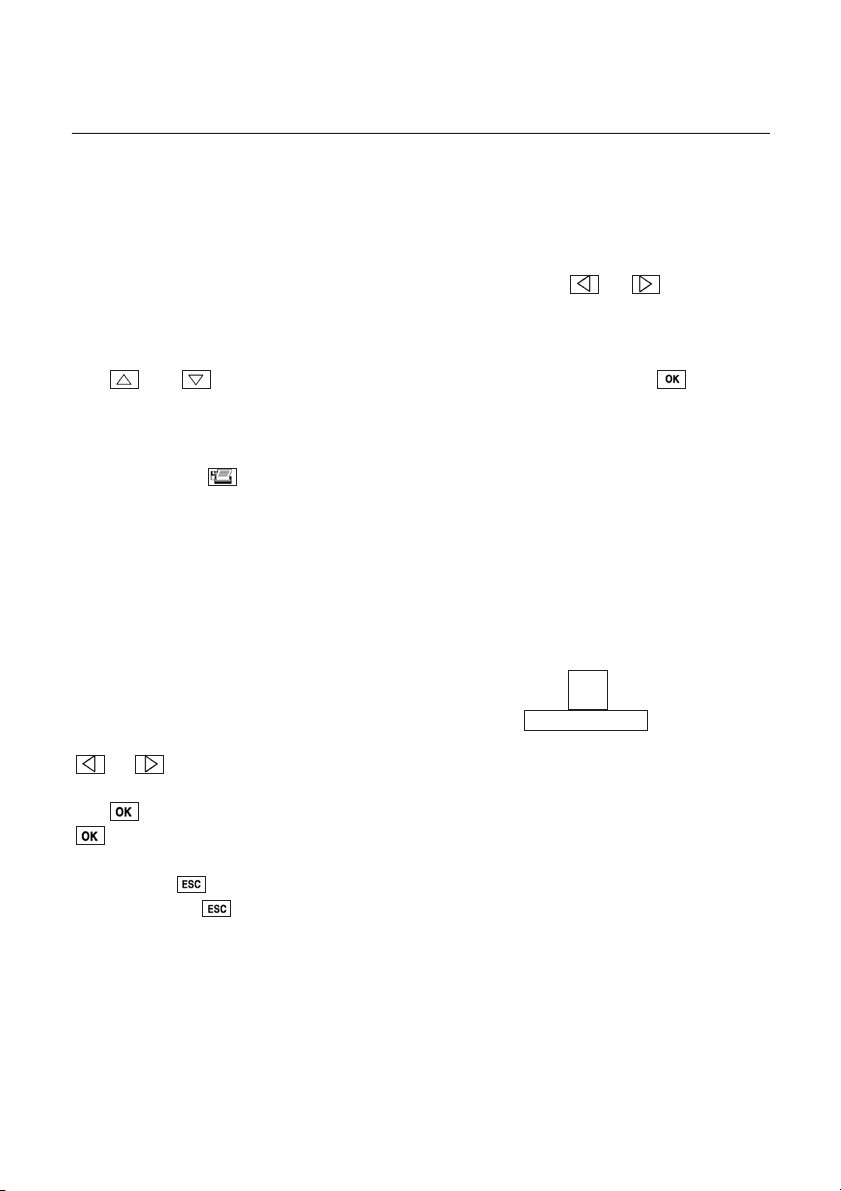
Function fields .......................................................................................................................8
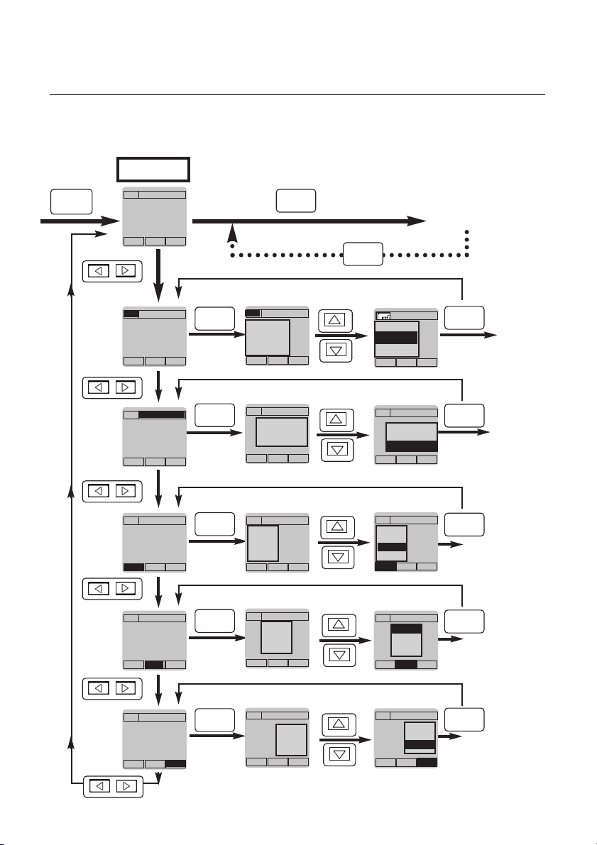
Menu overview / Configuration..............................................................................................9
Allocation options of function buttons ........................................................................10
Initial operation of printer
Attachable printer 0554.0570..............................................................................................12
Instrument and error messages ...............................................................................................15
Resetting instrument data ........................................................................................................16
Data management.....................................................................................................................17
Working with the barcode.........................................................................................................18
Examples of measuring tasks
Temperature measurement ..............................................................................................19
Humidity measurement ....................................................................................................24
aw value measurement.....................................................................................................28
Automatic storing..............................................................................................................30
Velocity measurement.......................................................................................................37
WBGT measurement.........................................................................................................44
NET measurement.............................................................................................................45
Pressure measurement .....................................................................................................46
rpm measurement .............................................................................................................46
Current/voltage measurement..........................................................................................47
Barometric measurement .................................................................................................48
Leak detection probe........................................................................................................49
CO measurement/ CO2measurement .............................................................................50
Power supply.............................................................................................................................51
Update on disk ..........................................................................................................................52
Technical data ...........................................................................................................................53
Ordering data.............................................................................................................................55
Index ...................................................................................................................................64
The conformity certificate confirms that the instruments meet
89/336/EWG guidelines.
©2002 Copyright Testo AG
The software and software structure included in the product testo 400 are protected by
copyright laws worldwide.

3
Introduction
Dear Customer
You have made the right decision by choosing a measuring instrument from Testo. Thousands of
customers buy our high standard products every year. There are at least 7 good reasons for doing so:
1) Cost - performance ratio. Reliable quality at a fair price.
2) Extended warranty times of up to 3 years - depending on instrument.
3) We have the ideal solutions for your measuring tasks based on our expert experience gained
over 40 years.
4) Our high quality standard is confirmed by the ISO 9001 certificate.
5) Of course, our instruments carry the CE symbol required by the EU.
6) Calibration certificates for all relevant parameters. Seminars, advice and calibration on location.
7) Our after-sales service. Ask for more details.
Your measuring instrument is a flexible, future-oriented system whose range of operations and
software can vary according to installation.
Once the instrument is switched on, you will receive information on the type of instrument installed,
the serial number as well as information on the current software version in the instrument. Additional
information on our service points, for example, can be printed (See page 16).
(See page 16).
The instruction manual describes the maximum available range of functions in the
testo 400.testo 650 and testo 950 have limited derived functions in relation to the probes which
can be connected and the parameters which can be analysed - See table:
testo 650 and testo 950 can also be subsequently upgraded to include the full range of functions of
testo 400.
We will also continue to make branch-specific and user-specific software updates for these
instruments available to you. All you need to do is register yourself as a user so that we can inform
you directly via NEWS.
This documentation describes the Software Version 2.0.
Parameter testo 400 testo 650 testo 950
Temperature °C x x x
Humidity %RH x x -
Pressure hPa ... bar x x -
Velocity m/s, m3/h x - -
Gas CO x x x
Gas CO2xxx
rpm x x x
Voltage V x x x
Current I x x x
WBGT °C x - -
NET °C x - -
i
Update on disk

4
Initial operation of instrument
Please read prior to operation
Do not measure on live parts.
Observe admissible storage and transport temperature as well as the operating temperature
(e.g. protect measuring instrument from direct sunlight).
Turn off the instrument when changing configurations (e.g. changing the probe) because the
characteristic values specific to the probe are only read by the instrument when switched on.
The V24 cable (barcode pen or PC connection) can be plugged in at any time.
If a PC cable is connected, a simultaneous print command is not possible.
Ensure that contacts are correct in probes with plug-on head.
Tighten the sleeve in the probe handle until the limit stop is reached.
The warranty is no longer valid if the instrument is opened, in the case of inexpert handling or
use of force.
Button cell - stores the
contents of the memory if
the rechargeable
batteries are empty or if
the battery is changed.
Testo rechargeable
battery Putting in batteries
Unscrew the back of the measuring instrument. Place the button
cell (Part no.: 0515.0028) in the opened battery compartment
with the “+” pole on top and put in the batteries or the Testo
rechargeable batteries (Part no. 0554.0196). Observe
polarization! Close battery compartment.
You will find further information on alternative power supply,
recharging mode, battery quality, recharging in the “Power
supply“ chapter. Refer to the index.
i
Power supply

5
Initial operation of instrument
A quick introduction is provided by the instrument and
system descriptions on pages 6-9.
This symbol stands for further information . Look
for the adequate word in the keyword context, further
informations are available on the indicated page.
Note: The measuring instrument should be switched off before
connecting a probe.
Once a probe has been attached and the measuring instrument has
been switched on, you will immediately receive current readings. In
the case of new instruments, you should update or define the data
saved in the instrument:
➾Date/Time:
➾Auto Off:
➾Units:
➾Type of printer used (the set printer must be activated
separately).
Some things can only be set via the PC software (see Ordering data):
➾Info (additional information on the chosen measurement location)
➾Your address.
The function buttons can be assigned once a probe is connected:
Press until such time that the corresponding function field is
shown inversely and then press .A list appears in the display
containing the allocation options available for the respective function
buttons when a certain probe is connected. Select the function
required via or and allocate to function button by pressing
(multiple allocation is not possible).
You can get to the other two function buttons via or .If
none of the functions fields are inversed once or is
pressed, then current data measurement is activated.
First measurement
i
i
Configuration
i
Function buttons
Function fields
Allocation options

6
Description of instrument
Printing/Storing
Cancel/
Restore
Connection:
8V DC mains unit
Arrow buttons move cursor in
the display
On/Off button
Function buttons
Function bar
The specified function (user
defined) is activated by pressing
the corresponding function
button
Infrared
interface for
printer
Attachment
for printer
• Serial interface (RS 232) for
connection to PC*
• Connection for barcode pen
4411..33
2255..11
1111..11
%RH
°C
td°C
Location
Hold Mean VOL
Display light
On/Off
Confirmation
The allocation of the probe connection
socket is freely selectable
(except in the case
of special functions such as calibration etc!)
1 2
Display
Function box:
Print/
Save/
Mains
connection/
Measuring program
mode (see Page 33)
Function box
Location
*testo Comsoft software, Version
3.0 or newer, is required for data
exchange with your PC.

7
Description of instrument
5 function fields are set up around the data display which provide information on
additional functions during measurement. In order to set up these functions which can be
activated directly, leave the measurement window by pressing or . The current
measurement is then interrupted. The activated function field is shown in white with a
black background (inversed).
The and buttons switch between the options stored for this field. shows all
the options available in an additional window which can then be selected.
The target location for the measured data is shown at the top left, if transmission is
activated via the button. The data is then stored in the memory or printed.
The measuring location is shown at the top right facilitating the allocation of the data
to the measuring location during printing and analysis.
Below are the 3 currently available functions. The meaning changes depending on the
menu. The description in the display also changes accordingly. Not all of the function
buttons are allocated in every menu or with every probe.
If none of the function fields are inversed after pressing
or this means that current data measurement is activated.
The button takes you from the measured value display to the main menu. Otherwise
activates the selected function or confirms the contents of the selected window.
By pressing , selected processes or functions can be cancelled or you can leave
submenus. The always takes you back to the menu window until the main menu or
the activated data display appears.
i
Function buttons

8
System description
Function fields
Assignment
option
Left
function button
Middle
function button
Right
function button
MEASURING
I/0 OK
Esc
OK
OK
OK
OK
OK
OK
OK
/
/
/
/
/
OK
OK
OK
List of
measuring
locations
stored in
instr.
Target for
data when
the Print
button is
pressed
mm
Lenzkirch
mm mm
mm
mm
Memory
Printer
Both
Memory
Printer
Both
Store
Cold store
Factory hall1
HOLD
MaxMin
Mean
m/s
HOLD
MaxMin
Mittel
m/s
HOLD
MaxMin
m/s
MaxMin
hPa = 0
m/s
MaxMin
hPa = 0
m/s
HOLD
MaxMin
m/s
Cold store
Factory hall1
Factory hall 2
Printer
Factory hall 2
Mean
Hold
m/s
Mean
Hold
m/s
Factory hall2
Mittel
Mean Mean Mean
Hold Hold Hold
41.3
25.1
11.1 Main mmenu
/
Lenzkirch

9
Menu overview
Configuration
MEMORY
PROBE
SPECIAL
INSTRUMENT
PRINT
LANGUAGE
READOUT
PROGRAMME
KEYLOCK
CONDITION
RESET
Start
Cycle Time
End
Save
Cancel
Lower limit
Upper limit
Manual
Date/Time
Memory full
Wrap around
No. of values
Date/Time
SMOOTH
T95-FAST
SURF. CORR
ADJUST
CALIBRATION
SCALING
RESET PARAMETER
PITOT FACTOR
CORR. FACTOR
VAC MODULE*
aw VALUE
DATE/TIME
AUTO OFF
UNITS
POWER
ADDRESS
PROTECTION
RESET DEFAULT
TEST
INSTR. DATA
CONFIGURATION
PRINTER TYPE
PRINT
LOGO/PARAM.
DEUTSCH
ENGLISH
MMaaiinnmmeennuu
Temp.
Humidity
abs. Press.
Abs. Alt.
barom. Pr.
diff. Press.
Density
Display
Memory
E2PROM
Beeper
Analog
attach. Printer
Testo Printer
*On request

10
Menu overview
Allocation options of function buttons
Lenzkirch
41.3
25.1
11.1
Allocation options of
function buttons:
HOLD
MAX/MIN
MEAN
VOL
hPa=0
hPa
m/s
Turb.
(blank)
CO=0
Start/Stop
T95
0.1 - 0.01
0-->0.0
Delta T
Delta P
aw value
NET
Send
freezes the last current reading on the display.
shows the largest/smallest display value since
switching on. If there is more than one value, all of
the display values are stored separately and
analysed.
for calculating mean value. This function is available
for all parameters.
extends the mean calculation by an additional set
measurement duration within the same log.
measures a new mean in a new log.
interrupts calculation of the mean value.
extends the display with the “m3/h” channel (volume
flow) when a velocity probe is connected. The
diameter of the channel, two side lengths or the area
can be given as the parameters. The duct dimensions
are individually saved and processed for every
measurement location.
carries out a zero-point calibration when the pressure
probe is connected.
“m/s” extends the display by the velocity value
calculated from pressure when a differential pressure
probe is connected.
“hPa” deactivates this channel.
calculates degree of turbulence when a comfort level
probe (0628.0009) is connected.
The function button is deactivated.
repeats the zero-point calibration if a CO probe is
connected.
CO=0
Turb.
hPa
m/s
hPa=0
Vol
End
New
Continue
Mean
MAXMIN
Hold
i
Standard volume flow

11
Menu overview
Allocation options of function buttons
starts a measurement program.
stops a measurement program.
uses the constants stored in PROBE - T95 FAST (also
depending on location) to extrapolate the change in
reading to the expected final value when a temperature
probe is connected. The function is particularly suited to
slow temperature probes. The constants are measured via
PC software.
switches resolution when a temperature probe is
connected (only for Pt100 or adjusted thermcouple
probes) and facilitates with these probes measurements
≥ +300° C and ≤ -100°C with a resolution of 0.1 ° C and
measurements ≤+300° C and ≥-100°C with a 0.01 ° C
resolution.
Calculates the difference between two displayed tempera-
ture values if two temperature probes are connected.
Calculates the difference from the two pressure values,
if two pressure probes (0638.1740, 0638.1840 or
0638.1940) are connected.
aw value measurement (water activity)
Calculates NET climate index
Sends current readings in ASCII format with unit to a
connected PC via connection cable 0554.0178 using the
RS232 interface. The values can be displayed, printed
and saved using the HyperTerminal program, for example.
Not all of the function buttons are allocated in every menu or
with every probe.
The meaning can change depending on the menu. The
description in the display changes accordingly.
Send
NET
aw-value
Delta P
Delta T
0.1 - 0.01
T95
Stop
Start
i
Temperature measurement
Pressure measurement
Humidity measurement
rpm measurement
Velocity measurement
i
aw value
i
NET

12
Initial operation
Attachable printer
Part no. 0554.0570
The testo 400/650/950 instruments have an interface for connecting
the attachable printer. Press ➀to release the lock.
The switch on the left side of the printer has the following 3 functions:
left: Off switch
middle: On switch
right: Line feed.
In the OFF mode, move the switch to line feed and if you keep this
position the character set stored in the printer will be printed as a test
print.
Changing batteries
Observe polarity marked in the battery section when putting in
batteries (4 x 1.5 V alkaline or corresponding rechargeable batteries).
Rechargeable batteries must be charged outside the printer e.g. using
the Testo recharger 0554.0110 (incl. 4 standard rechargeable
batteries).
Changing the paper
The paper section is at the top of the printer. Position the paper as
shown in diagram.
Note: The paper is thermal paper which means that only one side can
be printed. Therefore ensure that the paper is inserted properly.
Move slide switch to “Line feed” position so that the paper can run
through.
Note: The printer is not powered via the hand-held instrument, therefore it must always be
switched on and off separately.
After approx. 8 minutes inactivity the printer goes into a power-save mode to save
the battery. Switch the printer off and then on again to reactivate it.
Even in the power-save mode the printer uses up energy. The printer should be
switched off when not in use for longer periods of time.
➀
Off On Line feed

13
Data transfer
The attachable printer has a powerful bi-directional infrared interface
with data buffer in the printer. Once the button is pressed, the
data is transferred in the matter of seconds. The line of transmission
should be kept free of obstacles until the instrument has confirmed
transmission.
Note: If printing large amounts of text
- more than 1 m text -
we recommend you to attach the printer to the measuring
instrument.
Printout:
Initial operation
Attachable printer
Part no. 0554.0570
i
Printer
Printing logs
FFllooww--RReettuurrnn
1 m
30°
10°
20°
20°

14
Empty page

15
Instrument and error messages
Error message Possible causes Error elimination
Instrument error Numerous! Contact our
072304EF00 ← Note number! service department
Memory error No memory space available Erase memory
Memory not
available
Memory error Measurement program was Cancel meas. program
Meas. program is set up and is currently measuring or wait until
active finished
Printer error Check plug-in
or No connection to connection or infrared
printer is not printer transmission line
printing
Printer is switched off Switch on printer
Printer batteries are empty Change batteries in
printer
Printer in power-save mode Switch printer off
and then on again
Printer symbol top left Activate
is not activated in display. printer symbol
Wrong printer selected in Correct under
main menu. PRINT -
PRINTER TYPE
++++ Extreme application conditions Wait until
or (very strong currents near disturbance disappears
- - - - the measuring instrument)
Change lithium No or very low ESC, replace battery
battery Li battery in instrument if necessary
Self-test error Li battery was put in incorrectly
- - - - - - Probe unavailable
+ - + - + - Outside measuring range
- + + + + - Upper limit in measuring range
+ - - - - + Lower limit in measuring range
If we were unable to answer your question, please contact your distributor or Testo
Customer Service. You will find contact details in the Warranty booklet or in Internet at
www.testo.com
.

16
Resetting
You can reset your units to the factory settings via INSTRUMENT - RESET DEFAULT or
PROBE - RESET.
Current instrument data and settings can be printed via PRINT - INSTRUMENT DATA and PRINT -
CONFIGURATIONS.
Instrument data Configurations
i
Adjustment
IInnssttrruummeennttddaattaa
Address:
Testo GmbH
*******
*******
D-79853 Lenzkirch
Testo - Strasse 1
BRD
Service
07653 681 -0
Type: testo 400
V1.16 Sample
SN: 000 0101 816
System time:
25.12.1997
23:34:27
Accu: 4.9 %
Configurations
System time:
26.12.97
00:43:36
Memory:
Start: Date/Time
End: No. of values
Cycle Time 2 s
85 % free
6917 measured values
Scaling:
Channel1
0 to 20 mA/mV/V
0 to 100%RH
Channel2
0 to 20mA/mV/V
0 to 100%
Pitot factor: 1.00
Parameter:
Temp. 25.0 °C
Humidity 30.0 %
Abs. pressure 911 hPa
Density 1061.2 g/m2
Area 0.20 m3
Auto Off:
5 min

17
Data management
The proof value of the data measured is determined by the time, allocation of a location and other
conditions during the measurement. (Where, when, how and in what conditions was the
measurement carried out?).
For example, 23.4 °C is a measured value without reference and meaning. An actual value has
been taken completely out of its context. Additions such as 13.4.97/ 8:30 a.m./ cold store,
incubator or living room/ 17 °C connect the actual value with the desired value and this can be
assessed years later.
The values measured in the measuring instruments of the testo 400/650/950 series are constantly
accompanied by a location (top right in display). This information as well as date and time appear
as additional information in all of the printouts and in the PC files.
The location is selected in situ from a list stored in the measurement instrument:
Measurement menu →
Page+/Page- use to scroll through a long list of locations.
It is best to use the testo 400 module for testo Comsoft
software (from Version 3.0) to process the list.
You can also modify the list directly in the instrument:
LOCATION function box - Change function button.
Select with :
• New folder: You can also set up a folder to structure the
locations.
The layout is in a tree structure corresponding to
testo Comsoft software.
5 hierarchical levels (folders and sub-folders) can be
set up.
• New location: A new location can be set up
(see below about entering characters).
• Copy: You can change a saved location and save as a new
location. The original location will be retained. This is
ideal for numbering locations e.g. Hall 1, Hall 2,...
(see below about entering characters).
• Change: You can change a stored location (see below about entering characters).
The barcode number is retained after a new name has been saved.
• Delete: You can delete a location or folder from the list.
• Info (only for locations, not for folders): shows additional, attached information on the location
(entered via testo Comsoft software ).
ENTERING CHARACTERS VIA ALPHABET/DIGIT BOX:
Change to the required characters using the arrow buttons, select with . Use to select
lower case letters and special characters. The folder (maximum 8 characters) or the location
(maximum 15 characters) is copied into the list via the Take over button.
Page- Change Page+
1testo 400
.week 35/02
/
+ hall A1
+ hall A2
+ hall C3
Page- Change Page+
2testo 400
..hall A1
/
window L1
window L2
window L3
window R1
window R2
door 1
door 2

18
Working with the barcode
The barcode pen (No. 0554 0460) automates the allocation of measured data to a measuring
location.
If a barcode label is attached on location (produced using Comfort software, testo 400 module)
this can be read in with the barcode pen. The measuring instrument searches for the location in the
list to which these coded barcode numbers are allocated in the instrument memory. The location is
then written in the top right corner of the display.
The barcode pen can be plugged in and out when the instrument is switched on. Attaching the
barcode pen with the holder to the SoftCase (Accessory Part no. 0516.0401) makes handling
easier.
The barcode pen can be attached to the RS-232 socket on the side of the measuring instrument.
An audible signal follows.
If the signal does not sound, repeat the procedure. If the signal still does not sound this is an
indication that the barcode pen is not working properly. Please contact our service department.
After the signal has sounded, the barcode pen then goes into the power-save mode. This is
indicated by the pulsating laser diode.
Activate the barcode pen by holding the tip of the pen on a white surface e.g. the barcode label.
The laser then goes into continuous operation.
Run the pen directly over the barcode sample. Correct transmission is confirmed by an audible
signal. The selected location is then available.
If the barcode number on the label is not in the instrument list i.e. the read in barcode is unknown
to the instrument, a new location is automatically allocated. The PC software then searches in the
PC location data base to find out if this location already exists. If not, it is then set up.
If an unplanned location (without barcode) has to be measured, a name is set up in the function
box LOCATION at CHANGE - NEW LOCATION. The instrument generates a provisional number. The
final barcode number is then allocated in the PC software.

19
Temperature measurement
Task: - Repeated temperature measurement ➁at 30 measuring points with a thermocouple probe
➀specially adjusted to a Pt100 precision probe
- Printout with attachable printer ➂
➀Adjusting ...
a) a surface temperature probe e.g. 0614.9993 to a
precision Pt100 immersion probe, e.g. 0628.0015:
The temperature probe marked with * in the Ordering data has its own integrated memory
(EEPROM). Data on probes is saved here:
Main menu→→Probe - Adjustment (OFFSET correction)
- Surface correction (Gradient correction).
Connect both probes to the hand-held instrument. Connect the probe which is to be adjusted -
only an EEPROM probe (See Ordering data: marked with *) can be used - to socket 1 on the left.
Switch on instrument. Switch to main menu with and adjust via PROBE - ADJUSTMENT.
Immerse both probes in a bath at the future working temperature (at least 10 cm deep) and wait for
a stable temperature display in both probes. Start adjustment in the menu
(See display:”Adjust”). The differential temperature of the surface temperature probe to the Pt100
precision probe is stored here.
b) a probe with EEPROM using a separate precision measuring instrument:
Connect the probe to be adjusted to the left socket 1, switch on the instrument and confirm
PROBE-ADJUST in the main menu with .
The measured actual temperature is on line 1. The required temperature is specified by the
reference instrument.
Set the required temperature on line 2 using the cursor buttons.
The future displayed temperature values of this probe will be adjusted accordingly (=offset
correction). This offset, compared with the factory calibration, appears in the display when the
instrument is switched on:
OK
OK
Example:
Set required value: 25.0 °C
Offset correction: 1.22
Required value + offset correction = measured value
following factory calibration = current value of probe: 26.22
°C.
Probe 1
Adjust
Probe 1

20
Temperature measurement
Optimum accuracy only applies in the environment of the calibration
point. There may be deviations from the true desired value in other
temperature ranges.
Warning: If a probe is newly adjusted, the factory calibration data
is deleted. You can retrieve the original values via
PROBE - RESET
.
➁Measurement: Place the function display at the top left on the
Save (= disk symbol) symbol.
Return to the measurement menu by pressing . Switch off
measuring instrument. Plug in the newly calibrated probe to the
instrument on location and switch on. The probe socket is freely
selectable. Select the Location function field via and set
the required location with .
Press the button after every measurement and select the
required location before the next measurement.
A log is set up in the hand-held instrument memory each time the
button is pressed. The log includes the location, date and time,
all additional information, set correction values... and can be printed
under PRINT - CONFIGURATION.
➂ Printing all of the measured data following completion of the
measurement series: set the measuring location at top right. Call up
the log in the Main menu under MEMORY - READOUT and print by
pressing .
Note: The printer to be used when printing must be selected via
the menu PRINT -
PRINTER TYPE
.
Example:
Log with attachable
printer
Flow -
return
Other manuals for 400
4
This manual suits for next models
2
Table of contents
Other TESTO Measuring Instrument manuals

TESTO
TESTO 510 User manual

TESTO
TESTO Hygrotest 600 WH User manual

TESTO
TESTO 316-1 User manual

TESTO
TESTO 420 User manual

TESTO
TESTO 0636 6160 Quick start guide

TESTO
TESTO 460 Manual

TESTO
TESTO 0699 6446 Series User manual

TESTO
TESTO 400 User manual

TESTO
TESTO 0600.9430 User manual

TESTO
TESTO 417 User manual
Popular Measuring Instrument manuals by other brands

Doser
Doser DM 4 A operating instructions

engelmann
engelmann HCA e2 user manual

Servomex
Servomex Servotough SpectraScan 2400 user manual

ISOIL
ISOIL Isoflux IFX-F100 user manual

Leica Geosystems
Leica Geosystems Leica DISTO E7500 Quick start user manual

LuftLicht
LuftLicht CO2 traffic light operating instructions