Teuco HYDROSONIC User manual

MANUALE ISTALLAZIONE VASCHE
con e senza idromassaggio.
BATHTUBS INSTALLATION MANUAL
with and without whirlpool.
MANUEL D’INSTALLATION DES BAIGNOIRES
avec et sans hydromassage.
INSTALLATIONSANLEITUNG FÜR
Whirlpools und Wannen
MANUAL DE INSTALACIÓN DE BAÑERAS
con y sin hidromasaje.
INSTALLATIEHANDLEIDING VOOR BADEN
met en zonder hydromassage.
MANUAL DE INSTALAÇÃO DE BANHEIRAS
com e sem hidromassagem.
РУКOВOДCТВO ПO УCТAНOВКЕ ВAНН
с гидрoмaссaжнoй систeмoй или бeз нee.
∂°Ã∂πƒπ¢π√ ∂°∫∞∆∞™∆∞™∏™ °π∞ ª¶∞¡π∂ƒ∂™
ÌÂ Î·È ¯ˆÚ›˜ ˘‰ÚÔÌ·Û¿˙.
INSTRUKCJA MONTAŻU WANIEN
z hydromasażem lub bez.
KÜVET MONTAJ KILAVUZU
Hidro-masajlı ve hidro-masajsız.
UPUTSTVA ZA MONTAÎU KADE
s ili bez hidromasaÏe.
TOP - HYDROSONIC

2
I
IMPORTANTE: Leggere il presente manuale prima di procedere all’istallazione della vasca e conservarlo
insieme agli altri documenti.
Questo manuale è valido per il montaggio delle vasche con e senza idromassaggio.
NORMATIVE (Vedi il manuale allegato NORME PER L’ISTALLAZIONE):
Le vasche idromassaggio Teuco sono costruite e collaudate in conformità alla norme Europee per garantire la massima sicurezza
dell’utente.
MOVIMENTAZIONE DELLA VASCA:
Per togliere la vasca dall’imballo e durante la movimentazione sollevarla per il bordo o per il telaio.
CONTROLLI:
Dopo aver tolto la vasca dall’imballo controllare l'eventuale presenza di difetti.
L’AVVENUTA ISTALLAZIONE ESCLUDE LA GARANZIA IN CASO DI DANNI PROVOCATI DA URTI O ABRASIONI.
Verificare che gli allacci idraulici ed elettrici predisposti siano corrispondenti a quelli indicati nella scheda di preistallazione.
L
’istallazione della vasca deve avvenire a pavimento e pareti finite.
Tutti i nostri prodotti sono preventivamente collaudati, ispezionati ed imballati nel nostro stabilimento. L’eventuale presenza di acqua
all’interno della vasca è dovuta alla fase di collaudo; tuttavia prima di procedere all’istallazione definitiva della vasca con eventuali opere
murarie, effettuare un’ulteriore collaudo come descritto nella fase “PROVA DI FUNZIONAMENTO.”, verificando il perfetto funzionamento
del prodotto.
In caso di guasti o cattivo funzionamento dell’impianto rivolgersi a personale qualificato Teuco.
La ditta non risponde d’eventuali danni provocati da apparecchi manomessi impropriamente.
I dati e le caratteristiche riportati nel presente manuale non impegnano la Teuco Guzzini S.p.A., che si riserva il diritto di apportare tutte le
modifiche ritenute opportune senza obbligo di preavviso o sostituzione.
AVVERTENZE

3
I
SMONTAGGIO DEI PANNELLI
1SOLO VASCHE CON PANNELLI
Vasca con 3 pannelli Vasca con 2 pannelli Vasca con 2 pannelli Vasca con pannello frontale Vasca da angolo
con pannello frontale
A B
Fare leva con un cacciavite (A) nei punti indicati e sganciare (B) i pannelli dai piastrini di fissaggio.
Effettuare questa operazione per i pannelli seguendo l’ordine 1, 2, 3.
Esempi di pannellature
MESSA A LIVELLO
2
Posizionare la vasca nel luogo predisposto e livellarla regolando
prima i piedini perimetrali poi quelli centrali fino al contatto con il
pavimento.
Effettuare la regolazione in modo che rimanga una distanza
minima di 15 mm tra il pavimento e il bordo inferiore del
pannello della vasca per consentire la ventilazione
dell’impianto.

4
I
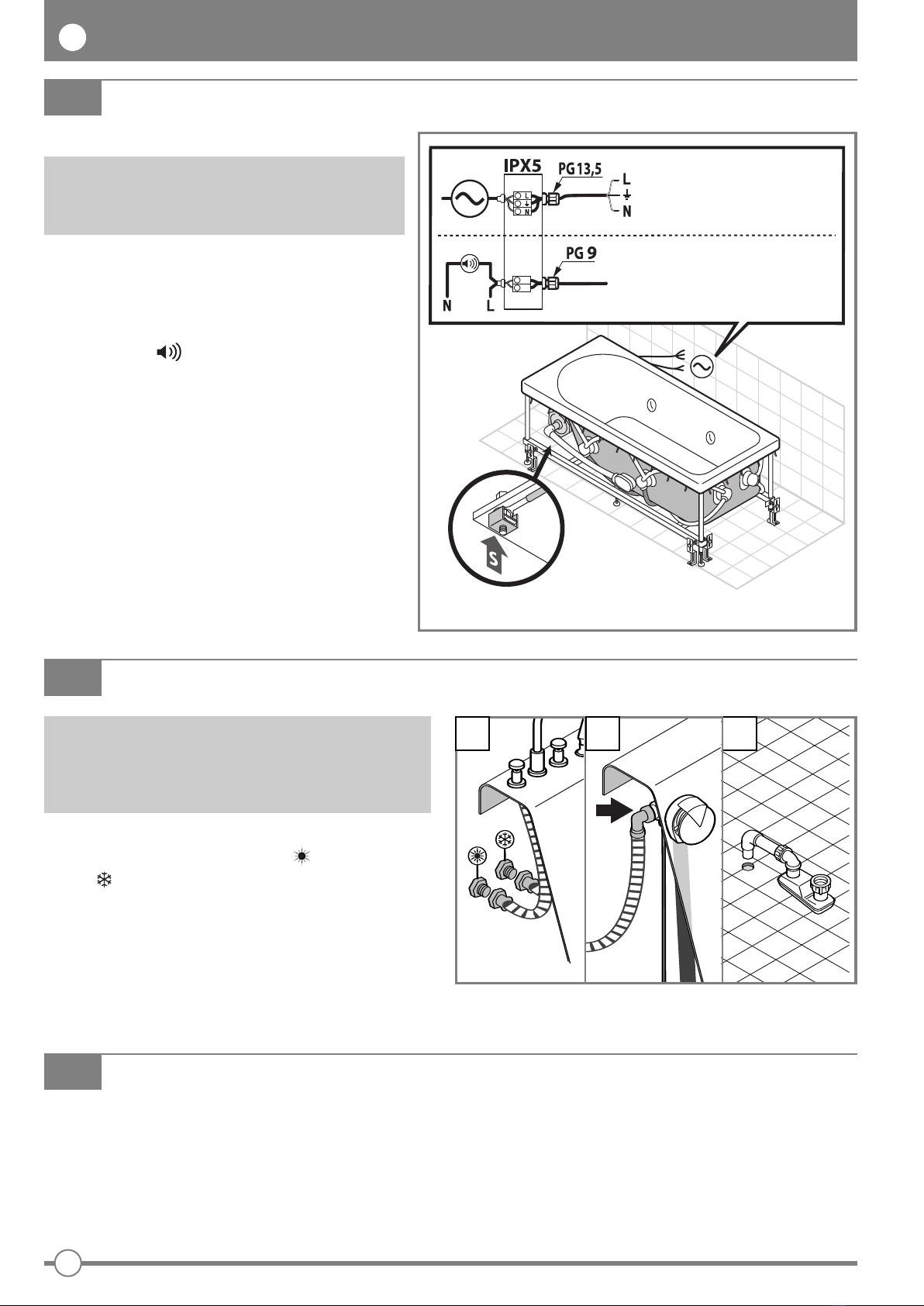
COLLEGAMENTI ELETTRICI (per vasche con idromassaggio)
3
Vedi il manuale allegato NORME PER L’ISTALLAZIONE.
Collegare la rubinetteria al morsetto S (nodo equipotenziale del
prodotto) per mezzo del cavo Giallo-Verde.
Utilizzare il morsetto S per la connessione di eventuali
conduttori esterni destinati al collegamento equipotenziale
supplementare.
Collegare il cavo di allarme - solo se la stanza da bagno é
munita del sistema di allarme.
Prima di collegare il prodotto accertarsi che le sue
caratteristiche elettriche (vedi dati di targa) siano adeguate
a quelle della rete di distribuzione elettrica.
COLLEGAMENTI IDRAULICI
4
VASCHE CON RUBINETTERIA (Fig.a)
Effettuare il collegamento della rubinetteria alla rete di alimentazione
acqua calda ( ) e fredda ( ) (per il montaggio della rubinetteria
vedere le istruzioni allegate).
VASCHE CON EROGAZIONE DAL TROPPO PIENO (Fig.b)
collegare il tubo dell’acqua miscelata sull’erogatore della colonna di
scarico. Attenersi alle normative locali in merito alla protezione
contro il riflusso.
ALLACCIO DI SCARICO (Fig.c)
Effettuare l’allaccio di scarico per mezzo del sifone in dotazione.
Qualora la durezza dell'acqua dell'impianto idrico sia elevata, per
garantire un buon funzionamento dell'impianto idromassaggio è
consigliabile installare un'addolcitore.
PROVA DI FUNZIONAMENTO E TENUTA D’ACQUA (per vasche con idromassaggio)
5
Terminati tutti gli allacci idraulici ed elettrici procedere al collaudo dell’impianto:
1) Pulire la vasca da eventuali sporcizie
2) Riempire la vasca fino al troppo pieno della colonna di scarico
3) Avviare l’idromassaggio (vedere manuale d’uso) in modo da verificare che non ci siano perdite d’acqua o segnalazione guasti sul pannello di
comando
4) Dopo aver eseguito il collaudo portare a termine l’istallazione della vasca come descritto nelle fasi seguenti.
a c
b
Marrone
Giallo Verde
Blu
Allaccio
Allarme
Allaccio
Elettrico

5
I
FISSAGGIO A PAVIMENTO
6
Fissare la vasca a pavimento sui piedini indicati nel disegno utilizzando le viti con stop in dotazione.
Vasca con tre pannelli Vasca con due pannelli Vasca con un pannello Vasca da angolo
SOLO VASCHE CON PANNELLI
MONTAGGIO DEI PANNELLI
7
Effettuati tutti gli allacci rimontare i pannelli precedentemente tolti seguendo l’ordine 1,2,3.
Accostare i pannelli alla vasca:
A - premere sul bordo superiore del pannello in modo che si inserisca tra le molle ed il bordo vasca.
B- premere il pannello nella parte inferiore in modo che si agganci ai piastrini di fissaggio (C).
SOLO VASCHE CON PANNELLI
B
A
C

6
I
ISTALLAZIONE DELLA VASCA DA INCASSO
8
Rispettare le precedenti fasi per l’istallazione della vasca ed
eseguire le seguenti indicazioni di montaggio.
Posizionare la vasca nel luogo predisposto ed effettuare il
livellamento per mezzo degli appositi piedini regolabili; LA VASCA
DEVE APPOGGIARE A PAVIMENTO SUGLI APPOSITI PIEDINI E
NON SUL BORDO PERIMETRALE.
Realizzare il muro perimetrale rientrato rispetto al bordo della vasca
al massimo di 15 mm IN MODO TALE CHE LA VASCA POSSA
ESSERE RIMOSSA PER EVENTUALI MANUTENZIONI FUTURE
SENZA CHE ESSO VENGA DANNEGGIATO.
MONTAGGIO DEL PANNELLO DI ISPEZIONE
(per vasche con idromassaggio)
Separare il pannello di ispezione e ventilazione (D) dal proprio
telaio (T).
Incassare nel muro perimetrale della vasca in prossimità della
pompa e dell’unità di potenza il telaio (T).
Rimontare il pannello di ispezione e ventilazione (D) sul telaio (T),
incassato al muro, fissandolo con le viti (Z).
Per consentire la manutenzione della vasca è necessario prevedere
che il collegamento tra il sifone e lo scarico a pavimento sia
smontabile ed ispezionabile.
SOLO VASCHE DA INCASSO
SILICONATURA
9
Per evitare infiltrazioni di acqua tra muro e bordo vasca applicare silicone NEUTRO NON ACETICO.
Nella Versione con 1,2 o 3 lati a muro è possibile montare i profili per vasca (vedi Kit Optional).

7
I

8
GB
IMPORTANT: Read this manual before proceeding with installation of the bathtub and keep it with the other
accompanying documents.
This manual is valid for the installation of tubs both with and without whirlpool.
STANDARDS (See the INSTALLATION STANDARDS manual attached):
Teuco whirlpool bathtubs are manufactured and tested in accordance with European standards to guarantee maximum user safety.
HANDLING THE BATHTUB:
When removing the bathtub from its packing and throughout handling operations, lift by the rim or the frame.
CHECKS:
Having removed the bathtub from the packing, inspect for possible defects.
DAMAGE CAUSED BY IMPACT OR ABRASION IS NO LONGER COVERED BY WARRANTY ONCE THE TUB HAS BEEN INSTALLED.
Make certain that plumbing and electrical connections are made as indicated in the preinstallation data sheet.
The tub must be installed directly on the floor and against finished walls.
All Teuco products are tested, inspected and packed before leaving the factory. When unpacked, the tub may contain traces of water from
factory testing; before proceeding with final installation and completing masonry works, if any, run a further test as described under
“OPERATION TEST” to make doubly certain that the product functions exactly as it should.
If faults or substandard operation of the system are discovered, contact a Teuco technician or approved service centre.
The company will acknowledge no liability for damage to appliances that have been tampered with.
Data and specifications indicated in the manual are not binding on the company: Teuco Guzzini SpA reserves the right to make such chan-
ges as are deemed appropriate without notice or obligation to update.
WARNINGS

REMOVING THE PANELS
1PANELLED BATHTUBS ONLY
Bathtub with 3 panels Bathtub with 2 panels Bathtub with 2 panels Bathtub with front panel Corner bathtub
with front panel
A B
Lever the panels off at the points indicated, using a screwdriver (A), and detach (B) from the retaining clips.
Remove the panels in the sequence indicated: 1-2-3.
Examples of panelled tubs
LEVELLING THE TUB
2
Position the bathtub in the selected place and level up, first by
adjusting the outermost feet, then bringing the middle feet into
contact with the floor.
Make the adjustment so as to leave a distance of 15 mm
minimum between the floor and the bottom edge of the panel
to allow for ventilation of the whirlpool system.
9
GB

GB
ELECTRICAL CONNECTIONS (tubs with whirlpool)
3
See the Installation Standards MANUAL ATTACHED .
Connect the taps to terminal S (equipotential bonding point) with
the Yellow-Green wire.
Use terminal S for the connection of any external wires that
need to be equipotentially bonded.
Connect the alarm - only if the bathroom is equipped with
an alarm system.
Before making any electrical connections, check that the
rated voltage and current of the appliance (see data plate)
are matched to the mains power supply.
PLUMBING CONNECTIONS
4
BATHTUBS WITH TAPS (Fig. a)
Connect the taps to the hot water supply ( ) and the cold water
supply ( ) (for assembly of the taps, refer to the instructions
attached).
BATHTUBS WITH COMBINED OVERFLOW AND FILLER SPOUT
(Fig. b)
Connect the hot-and-cold mix hose to the overflow filler spout.
Be certain to observe local bylaws on backflow protection.
DRAIN CONNECTION (Fig. c)
Connect the waste to the drain using the trap provided.
To ensure troublefree operation of the whirlpool system in areas
with particularly hard water, it is advisable to install a water
softener.
a
OPERATION AND WATERTIGHTNESS TEST (tubs with whirlpool)
5
Having made all the plumbing and electrical connections, proceed to test the system:
1) Clean any dirt from the tub
2) Fill the tub up to the level of the overflow
3) Start the whirlpool (see user manual), then proceed to check that there are no leaks, and no error messages displayed on the control panel.
4) Having tested the system, complete the installation of the bathtub as described below.
c
b
10
GB
Brown
Green-Yellow
Blue
Alarm
connection
Electrical
connection

11
GB
FIXING TO THE FLOOR
6
Anchor the bathtub to the floor by fixing the feet as indicated in the drawing, using the screws and masonry plugs provided.
Bathtub with three panels Bathtub with two panels Bathtub with one panel Corner bathtub
PANELLED BATHTUBS ONLY
FITTING THE PANELS
7
Having made all the connections, refit the panels removed previously in the order indicated: 1-2-3.
Offer the panels to the tub:
A - press the top edge of the panel inwards so that it locates between the springs and the rim of the tub.
B - press forward on the lower part of the panel so that it engages with the retaining clips (C).
PANELLED BATHTUBS ONLY
B
A
C
GB

12
GB
INSTALLATION OF BUILT-IN BATHTUB
8BUILT-IN BATHTUBS ONLY
Observe the general standards and procedures descri-
bed above, and complete the installation as follows.
Position the bathtub in the selected place and level up
by raising or lowering the adjustable feet as appropria-
te.
THE TUB MUST SIT DIRECTLY ON THE FLOOR SO
THAT THE WEIGHT IS TAKEN BY THE FEET, AND
NOT BY THE RIM.
Build the surround wall with the inside face set in from
the edge of the rim by no more than 15 mm SO THAT
THE TUB CAN BE LIFTED OUT SUBSEQUENTLY FOR
MAINTENANCE PURPOSES, IF NEED BE, WITHOUT
BEING DAMAGED.
MOUNTING THE INSPECTION AND VENTILATION
PANEL (for bathtubs with whirlpool)
Separate the inspection and ventilation panel (D)
from its frame (T).
Insert the frame (T) into the perimeter wall near the
pump and the power unit.
Remount the inspection and ventilation panel onto
the frame (T) and fasten it with the screws (Z).
To allow proper maintenance of the tub, the connection
between the waste trap and the drain must be made in
such a way as to enable removal and inspection.
SEALANT
9
To prevent water from penetrating between the rim and the wall, seal with NON ACETIC NEUTRAL silicone.
Versions with 1, 2 or 3 sides against the wall can be finished with trims (see Optional kits).

13
GB

14
F
IMPORTANT : Lire le présent manuel avant de procéder à l’installation de la baignoire et le conserver avec
les autres documents.
Ce manuel concerne le montage des baignoires avec et sans hydromassage.
NORMES (Consultez le manuel en annexe CONSIGNES POUR L’INSTALLATION) :
Les baignoires d’hydromassage Teuco sont fabriquées et testées conformément aux normes européennes pour garantir la sécurité totale de
l’utilisateur.
MANUTENTION DE LA BAIGNOIRE :
Pour retirer la baignoire de son emballage et durant la manutention, la soulever par le bord ou par le châssis.
CONTRÔLES :
Après avoir retiré la baignoire de son emballage, contrôler éventuellement si elle présente des défauts.
APRÈS L’INSTALLATION, LA GARANTIE NE RÉPOND PLUS DES DOMMAGES PROVOQUÉS PAR LES CHOCS OU LES
ABRASIONS.
Vérifier que les raccordements hydrauliques et électriques prédisposés correspondent à ceux qui sont indiqués sur la fiche de
préinstallation.
Installer la baignoire après avoir posé le revêtement du sol et fini les parois.
Tous nos produits sont testés, contrôlés et emballés dans notre usine. La présence éventuelle d’eau à l’intérieur de la baignoire est due
aux tests; avant de procéder à l’installation définitive de la baignoire qui pourrait prévoir des ouvrages de maçonnerie, faire un test
supplémentaire en suivant les explications de la phase “TEST DE FONCTIONNEMENT” pour vérifier si la baignoire fonctionne
correctement.
En cas de panne ou de dysfonctionnement du circuit, s’adresser au personnel qualifié Teuco.
La société ne répond pas des dommages éventuels provoqués par des appareils manipulés de façon impropre.
Les données et les caractéristiques indiquées dans le manuel n’engagent pas Teuco Guzzini S.p.A. qui se réserve le droit de modifier ses
produits sans préavis ni remplacement.
AVERTISSEMENTS

DÉMONTAGE DES PANNEAUX
1BAIGNOIRES HABILLÉES UNIQUEMENT
Baignoire habillée sur 3
côtés
Baignoire habillée sur 2
côtés
Baignoire habillée sur 2
côtés
Baignoire avec panneau
avant
Baignoire d’angle
avec panneau avant
A B
Soulevez les points indiqués à l'aide d'un tournevis (A) et décrochez (B) les panneaux des plaquettes de fixation.
Effectuez cette opération pour les panneaux en respectant l'ordre 1, 2, 3.
Exemples d’habillages
MISE À NIVEAU
2
Placez la baignoire à l’endroit choisi et mettez-la de niveau en
réglant d’abord les pieds extérieurs puis les pieds centraux jusqu’à
ce qu’ils entrent en contact avec le sol.
Procédez à ce réglage de sorte qu’il reste au moins 15 mm
entre le sol et le bord inférieur du panneau de la baignoire afin
de garantir une bonne ventilation au niveau du circuit.
15
F

16
F
BRANCHEMENTS ELECTRIQUES (pour baignoires avec hydromassage)
3
Consultez le manuel en annexe CONSIGNES POUR
L’INSTALLATION.
Reliez la robinetterie à la borne S (noeud équipotentiel) par
l’intermédiaire du câble Jaune-Vert.
Utilisez la borne S pour la connexion d’éventuels conducteurs
externes destinés au branchement équipotentiel
supplémentaire.
Branchez le câble d’alarme - uniquement si la salle de
bains est dotée du système d’alarme.
Avant de procéder au raccordement, assurez-vous que les
caractéristiques électriques de l’appareil (voir données sur la
plaquette) correspondent à celles du réseau de distribution
électrique.
RACCORDEMENTS HYDRAULIQUES
4
BAIGNOIRES AVEC ROBINETTERIE (Fig. a)
Raccordez la robinetterie au réseau d’alimentation en eau chaude
( ) et froide ( ) (pour le montage de la robinetterie, suivez les
instructions jointes).
BAIGNOIRES AVEC TROP-PLEIN (Fig. b)
Reliez le tuyau du mélange d’eau sur la buse de la colonne de
vidage. Respectez les normes locales en matière de protection
contre le reflux.
RACCORD D’ÉVACUATION (Fig. c)
Procédez au raccordement du conduit d’évacuation en installant le
siphon fourni.
Si la dureté de l’eau du circuit hydrique est importante, il est
conseillé d’installer un adoucisseur pour garantir le
fonctionnement parfait du circuit d’hydromassage.
a
TEST DE FONCTIONNEMENT ET D’ÉTANCHÉITÉ (pour baignoires avec hydromassage)
5
Après avoir terminé tous les raccordements hydrauliques et électriques, procédez au test du circuit :
1) Nettoyez la baignoire pour éliminer toute trace de saleté
2) Remplissez la baignoire jusqu’au trop-plein de la colonne de vidage
3) Mettez l’hydromassage en marche (voir manuel d’utilisation) afin de vérifier qu’il n’y a aucune fuite d’eau ni signalisation de pannes sur le
panneau de commande
4) Après le test, terminez l’installation de la baignoire en suivant les explications des phases suivantes.
c
b
Marron
Jaune/Vert
Bleu
Branchement
Alarme
Branchement
électrique

FIXATION AU SOL
6
Fixez la baignoire au sol sur les pieds indiqués sur le dessin à l’aide des vis avec cheville d’arrêt, fournies dans le kit.
Baignoire habillée sur 3 côtés Baignoire habillée sur 2 côtés Baignoire habillée sur 1 côté Baignoire d’angle
BAIGNOIRES HABILLÉES UNIQUEMENT
MONTAGE DES PANNEAUX
7
Une fois tous les raccordements terminés, remontez les panneaux que vous aviez déposés en suivant l’ordre 1,2,3.
Approchez les panneaux de la baignoire :
A - appuyez sur le bord supérieur du panneau de sorte qu’il s’emboîte entre les ressorts et le bord de la baignoire;
B - enfoncez la partie inférieure du panneau de sorte qu'il s'emboîte dans les plaquettes de fixation (C).
BAIGNOIRES HABILLÉES UNIQUEMENT
B
A
C
17
F

18
F
INSTALLATION DE LA BAIGNOIRE ENCASTRÉE
8BAIGNOIRES ENCASTRÉES UNIQUEMENT
Respectez les phases précédentes pour l’installation de
la baignoire et procédez au montage de la façon sui-
vante.
Placez la baignoire à l’endroit choisi et mettez-la de
niveau en intervenant sur les pieds réglables.
LA BAIGNOIRE DOIT ÊTRE POSÉE AU SOL SUR LES
PIEDS PRÉVUS À CET EFFET ET NON PAS SUR LE
BORD PÉRIMÉTRAL.
Réalisez le mur périmétral au maximum à 15 mm
en-deçà du rebord DE SORTE À POUVOIR RETIRER
LA BAIGNOIRE SANS L’ENDOMMAGER EN CAS D’EN-
TRETIEN.
MONTAGE DU PANNEAU D’INSPECTION ET DE
VENTILATION (pour baignoires avec hydromassa-
ge)
Séparez le panneau d’inspection et de ventilation
(D) de son châssis (T).
Montez le châssis (T) sur le mur en maçonnerie à
proximité de la pompe et de l’unité de puissance.
Remontez le panneau d’inspection et de ventila-
tion(D) sur le châssis (T),encastré au mur, en le
fixant à l’aide des vis (Z).
Pour l’entretien de la baignoire, prévoyez de pouvoir
démonter et inspecter le raccordement entre le siphon
et l’évacuation au sol.
SILICONAGE
9
Pour éviter toute infiltration d’eau entre les parois et la baignoire, posez un mastic silicone NEUTRE SANS ACÉTATE.
Dans la version pour pose murale sur 1, 2 ou 3 côtés, il est possible de monter les profilés pour baignoire (voir Kit en option).

19
F

20
D
WICHTIGER HINWEIS: Lesen Sie diese Anleitung vor Installation des Whirlpools bzw. der Wanne durch und
bewahren Sie sie mit der übrigen Dokumentation auf.
Diese Anleitung betrifft die Installation von Whirlpools und Wannen.
NORMEN (Siehe beiliegende Anleitungen INSTALLATIONSVORSCHRIFTEN):
Die TEUCO Whirlpools garantieren höchste Benutzersicherheit, da sie den einschlägigen europäischen Normen entsprechen und eine
technische Abnahmeprüfung durchlaufen.
HANDHABUNG DES WHIRLPOOLS/DER WANNE:
Fassen Sie den Whirlpool/die Wanne beim Auspacken und Handhaben am Rand bzw. Rahmen an.
ÜBERPRÜFUNGEN:
Überprüfen Sie den Whirlpool/die Wanne nach dem Auspacken auf etwaige Mängel.
MIT DER INSTALLATION ERLISCHT DIE GARANTIE AUF SCHÄDEN DURCH STÖSSE ODER KRATZER.
Überprüfen Sie die Entsprechung der hergestellten Wasser- und Stromanschlüsse mit den Vorlagen im Installationsblatt.
Die Installation muss nach Fertigstellung des Boden- und Wandbelags erfolgen.
All unsere Produkte werden im Werk abgenommen, inspiziert und verpackt. Etwaige Wasserrückstände in Whirlpool/Wanne rühren von
der werkseitigen Abnahmeprüfung her. Sie sollten vor der endgültigen Installation des Whirlpools/der Wanne durch bauliche Maßnahmen
eine weitere Abnahmeprüfung nach den Angaben im Schritt “BETRIEBSTEST “ durchführen und hierbei die einwandfreie Funktion des
Produkts nachweisen.
Bei Betriebsstörungen der Anlage wenden Sie sich bitte ausschließlich TEUCO Fachpersonal.
Der Hersteller haftet nicht für Schäden, die auf unsachgemäß durchgeführte Wartungs- oder Reparaturarbeiten zurückzuführen sind.
Teuco Guzzini Spa weist darauf hin, daß die in der Anleitung angegebenen Daten nicht bindend sind und behält sich das Recht vor, ohne
Vorankündigung alle für notwendig erachteten Änderungen vorzunehmen, ohne dass sich daraus Ersatzansprüche ableiten lassen.
HINWEISE
Table of contents
Languages:
Other Teuco Bathtub manuals

Teuco
Teuco 254 User manual

Teuco
Teuco T08 User manual

Teuco
Teuco Accademia T13 User manual

Teuco
Teuco Hydroline T70 User manual

Teuco
Teuco 543-Y Series User manual

Teuco
Teuco HYDROTOP 543 User manual

Teuco
Teuco S20 Hydroline User manual

Teuco
Teuco HYDROSONIC Hydrosilence User manual

Teuco
Teuco iBordi T12 User manual

Teuco
Teuco 629 User manual
Popular Bathtub manuals by other brands

Crosswater
Crosswater US-N8ECS installation instructions

Laufen
Laufen PRO 2.3295.5.000.615.1 manual

Aquatica Digital
Aquatica Digital Arabella Aquastone Bathtub Installation & Care Manual

American Standard
American Standard Ellisse Elite 2711EC Specifications

Porcelanosa
Porcelanosa KRION PURE installation guide

Ella's Bubbles
Ella's Bubbles Standard owner's manual