EVM User's Guide: UCC217XXQDWEVM-054
UCC217xx and ISO5x5x Half-Bridge EVM User's Guide for
Wolfspeed 1200-V SiC Platforms
ABSTRACT
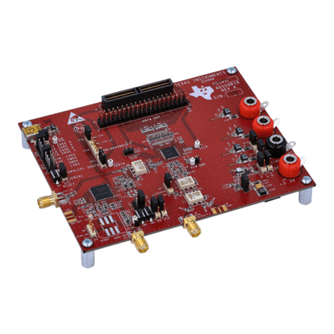
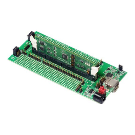
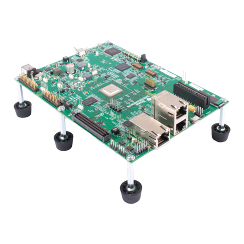
The UCC217XXQDWEVM-054 is a compact, half-bridge gate driver board consisting of two single-channel
isolated gate drivers. It provides isolated bias supply, drive current, protection and monitoring needed for driving
several different models of Wolfspeed silicon-carbide (SiC) MOSFET modules and other IGBT or SiC MOSFET
modules with a similar pinout. The on-board DC-DC transformers can provide adjustable isolated voltage.
The board's compact form factor, combined with UCC217xx's 5.7kVrms reinforced isolation, makes it a good
candidate for doing high voltage tests, such as double-pulse tests and short-circuit tests, with the Wolfspeed
SiC modules. The board can also be used with all variants of the UCC217xx and ISO5x5x family with minimal
on-board modifications.
This user's guide describes the characteristics, operation and use of the UCC217XX-054 Evaluation Module
(EVM). It also includes instructions to adjust different gate driver parameters, such as voltage supply and drive
strength, as well as instructions to modify the EVM to be compatible with different UCC217xx and ISO5x5x
variants. A complete schematic diagram, printed circuit board layouts, and bill of materials are included in this
document.
Table of Contents
1 General TI High Voltage Evaluation User Safety Guidelines.............................................................................................. 2
2 Module and Gate Driver Compatibility..................................................................................................................................4
2.1 Supported Wolfspeed Modules and Evaluation Platforms................................................................................................. 4
2.2 Supported Gate Drivers..................................................................................................................................................... 4
3 System Overview and Functions.......................................................................................................................................... 6
3.1 Features............................................................................................................................................................................. 6
3.2 Specifications..................................................................................................................................................................... 6
3.3 PCB Pinout.........................................................................................................................................................................7
3.4 Block Diagram....................................................................................................................................................................7
4 Using the EVM.......................................................................................................................................................................13
4.1 Equipment List................................................................................................................................................................. 13
4.2 Test Setups and Procedures............................................................................................................................................ 13
5 EVM Example Measurements.............................................................................................................................................. 16
5.1 Short-Circuit Testing.........................................................................................................................................................16
5.2 Analog Sensing................................................................................................................................................................ 17
6 EVM Tuning........................................................................................................................................................................... 19
6.1 Adjust Power Supplies..................................................................................................................................................... 19
6.2 Adjust Drive Strength....................................................................................................................................................... 20
6.3 Adaptations for Other ISO5x5x / UCC217xx Variants......................................................................................................20
7 Hardware Design Files......................................................................................................................................................... 22
7.1 Schematics.......................................................................................................................................................................22
7.2 PCB Layouts.................................................................................................................................................................... 24
7.3 Bill of Materials (BOM)..................................................................................................................................................... 27
8 Additional Information..........................................................................................................................................................33
8.1 Trademarks...................................................................................................................................................................... 33
www.ti.com Table of Contents
SLUUCK0 – SEPTEMBER 2023
Submit Document Feedback
UCC217xx and ISO5x5x Half-Bridge EVM User's Guide for Wolfspeed 1200-V
SiC Platforms
1
Copyright © 2023 Texas Instruments Incorporated
