1
SBAU321A–November 2018–Revised August 2019
Submit Documentation Feedback Copyright © 2018–2019, Texas Instruments Incorporated
BOOSTXL-ADS7142-Q1 BoosterPack™ Plug-In Module
User's Guide
SBAU321A–November 2018–Revised August 2019
BOOSTXL-ADS7142-Q1 BoosterPack™ Plug-In Module
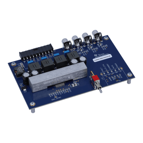
The ADS7142-Q1 BoosterPack™ plug-in module (BOOSTXL-ADS7142-Q1) allows users to evaluate the
functionality of Texas Instruments' ADS7142-Q1 nanopower, dual-channel programmable sensor monitor.
This user’s guide describes both the hardware platform showcasing the ADS7142-Q1 device and the
graphical user interface (GUI) software used to configure the various modes of operation of this device.
Contents
1 Introduction ................................................................................................................... 2
2 BOOSTXL-ADS7142-Q1 EVM Overview................................................................................. 3
3 BOOSTXL-ADS7142-Q1 EVM Initial Setup.............................................................................. 5
4 ADS7142-Q1 GUI Functional Modes.................................................................................... 13
5 Bill of Materials, Printed-Circuit Board Layout, and Schematics..................................................... 22
List of Figures
1 ADS7142-Q1 EVM Block Diagram........................................................................................ 2
2 BOOSTXL-ADS7142-Q1 Top Level Overview........................................................................... 3
3 Installation of browser extension and TI Clould Agent.................................................................. 5
4 MSP432E401Y LaunchPad™ 5V-OTG Jumper and Debug Port Location.......................................... 6
5 UNIFLASH Programming Setup........................................................................................... 6
6 Successful FLASH Program ............................................................................................... 7
7 BOOSTXL-ADS7142-Q1 Stacked on MSP432E401Y LaunchPad™ ................................................ 8
8 ADS7142-Q1 GUI Landing Page.......................................................................................... 9
9 ADS7142-Q1 Register Map Page........................................................................................ 10
10 ADS7142-Q1 Mode Configuration Page ................................................................................ 11
11 ADS7142-Q1 General Instructions Page................................................................................ 12
12 Data Capture in Start Burst Mode ....................................................................................... 13
13 Data Capture in Stop Burst Mode........................................................................................ 14
14 Operation in Pre Alert Mode.............................................................................................. 15
15 Operation After Alert Condition........................................................................................... 16
16 Operation in Post Alert Mode............................................................................................. 17
17 Operation in High Precision Mode ....................................................................................... 18
18 Operation in Default Manual Mode ...................................................................................... 19
19 Operation in Auto Manual Mode ......................................................................................... 20
20 BOOSTXL_ADS7142-Q1 PCB Top Overlay ........................................................................... 24
21 BOOSTXL-ADS7142-Q1 Top Layer Copper and Silkscreen......................................................... 25
22 BOOSTXL-ADS7142-Q1 Bottom Layer Copper and Silkscreen..................................................... 26
23 ADS7142-Q1 BoosterPack™ Schematic Diagram..................................................................... 27
List of Tables
1 Input Connector and Channel Configuration............................................................................. 3
2 Modification Required for NTC Monitoring.............................................................................. 21
3 Bill of Materials ............................................................................................................. 22
