List of Figures
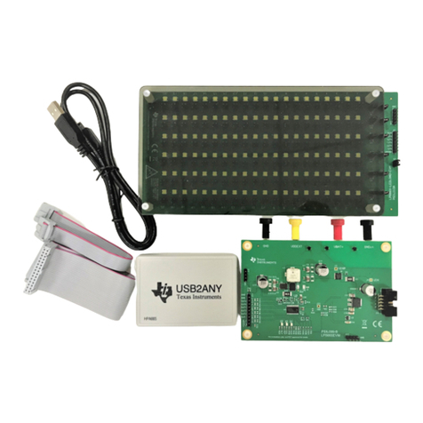
Figure 2-1. Hardware Included with OPT3004DTSEVM Kit........................................................................................................ 4
Figure 3-1. OPT3004DTSEVM Hardware Setup......................................................................................................................... 6
Figure 4-1. OPT3004DTSEVM Software-Installation File............................................................................................................8
Figure 4-2. OPT3004DTSEVM Software-Installation Launch......................................................................................................9
Figure 4-3. OPT3004DTSEVM Software-Installation Prompts.................................................................................................... 9
Figure 4-4. OPT3004DTSEVM Software-Installation Prompts.................................................................................................. 10
Figure 4-5. OPT3004DTSEVM Software-Installation Prompts.................................................................................................. 10
Figure 4-6. OPT3004DTSEVM Software-Installation Prompts.................................................................................................. 11
Figure 4-7. OPT3004DTSEVM Software-Installation Prompts.................................................................................................. 11
Figure 4-8. OPT3004DTSEVM Software-Installation Prompts.................................................................................................. 12
Figure 4-9. Typical Hardware Connection................................................................................................................................. 13
Figure 4-10. Typical Response After Connecting OPT3004DTSEVM to the Computer............................................................ 13
Figure 4-11. OPT3004 Main Operation Screen......................................................................................................................... 14
Figure 4-12. Hardware Error Message...................................................................................................................................... 14
Figure 4-13. GUI Capture Running............................................................................................................................................15
Figure 4-14. Latte Scripts Window.............................................................................................................................................17
Figure 4-15. Registers View.......................................................................................................................................................18
Figure 5-1. OPT3004 Coupon Board Schematic....................................................................................................................... 20
Figure 5-2. PCB Top Layer........................................................................................................................................................ 21
Figure 5-3. PCB Bottom Layer...................................................................................................................................................21
Figure 5-4. PCB Top-Layer Assembly Drawing......................................................................................................................... 22
Figure 5-5. PCB Bottom-Layer Assembly Drawing....................................................................................................................22
Figure 5-6. OPTMBEVM Schematic.......................................................................................................................................... 23
Figure 5-7. PCB Top Layer........................................................................................................................................................ 24
Figure 5-8. PCB Bottom Layer...................................................................................................................................................24
Figure 5-9. PCB Top-Layer Assembly Drawing......................................................................................................................... 25
Figure 5-10. PCB Bottom-Layer Assembly Drawing..................................................................................................................25
Figure 6-1. OPT3004DTSEVM on Microsoft® Windows® 7 With Drivers not Installed..............................................................27
1 Trademarks
Windows 10®, Microsoft®, and Windows® are registered trademarks of Microsoft Corporation.
All trademarks are the property of their respective owners.
www.ti.com Trademarks
SBOU274 – DECEMBER 2021
Submit Document Feedback
OPT3004DTSEVM User's Guide 3
Copyright © 2021 Texas Instruments Incorporated
