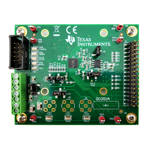
Texas Instruments TPS61177AEVM User manual
Other Texas Instruments Control Unit manuals
Texas Instruments
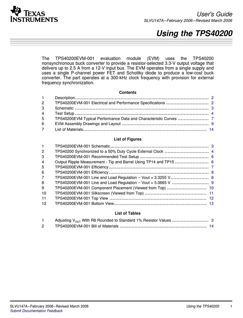
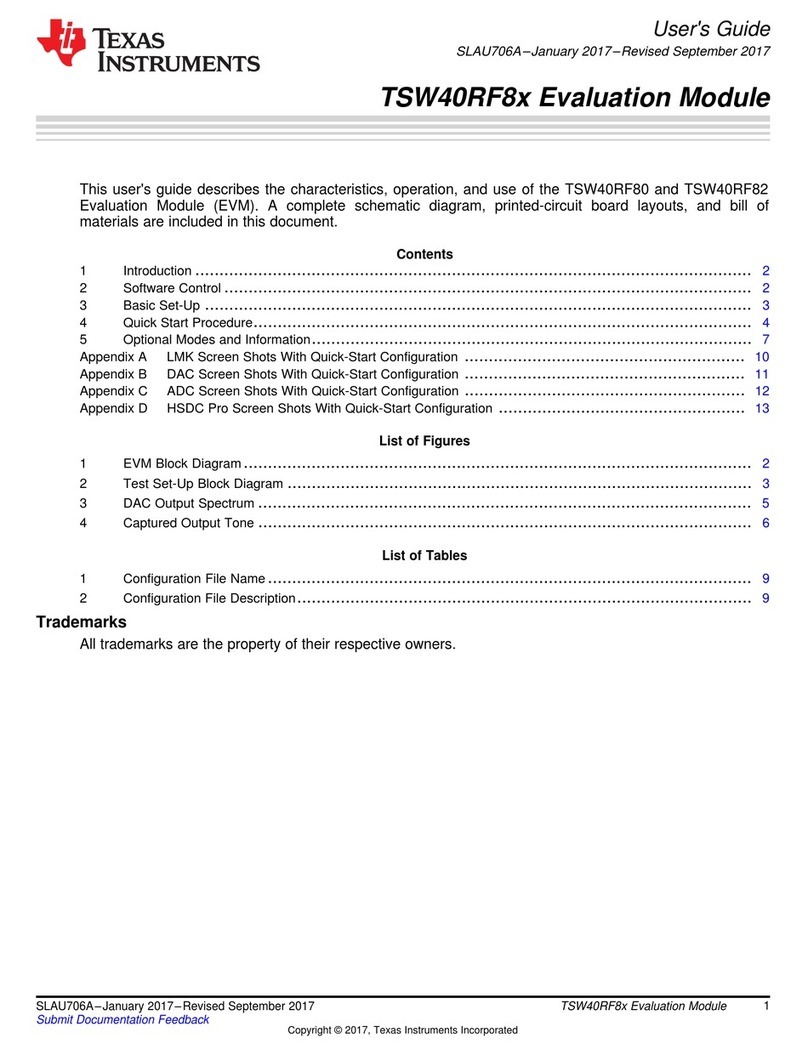
Texas Instruments TSW40RF8 Series User manual
Texas Instruments
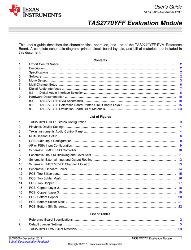
Texas Instruments TAS2770YFF User manual
Texas Instruments
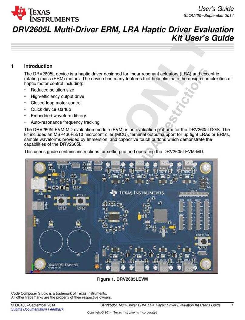
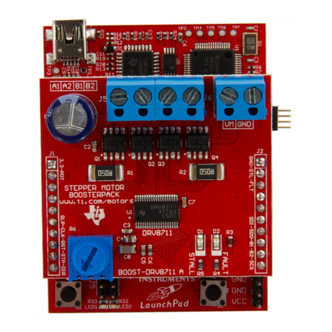
Texas Instruments BOOST-DRV8711 User manual
Texas Instruments
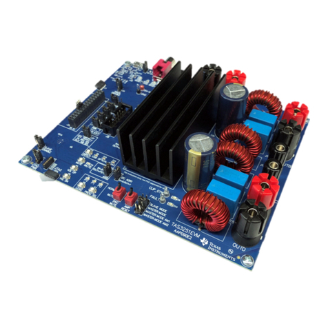
Texas Instruments TAS3251 User manual
Texas Instruments
Texas Instruments bq2023EVM-001 User manual
Texas Instruments
Texas Instruments TPS53128 User manual
Texas Instruments
Texas Instruments TSU6721EVM User manual
Texas Instruments
Texas Instruments MCT8316ZTEVM User manual
Texas Instruments
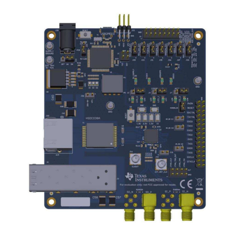
Texas Instruments DP83869EVM User manual
Texas Instruments
Texas Instruments TPS61020EVM User manual
Texas Instruments
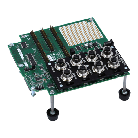
Texas Instruments TMDS64DC01EVM User manual
Texas Instruments
Texas Instruments TPS61280-585 User manual
Texas Instruments
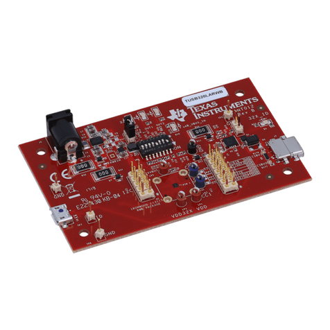
Texas Instruments TUSB320-LA-EVM User manual
Texas Instruments
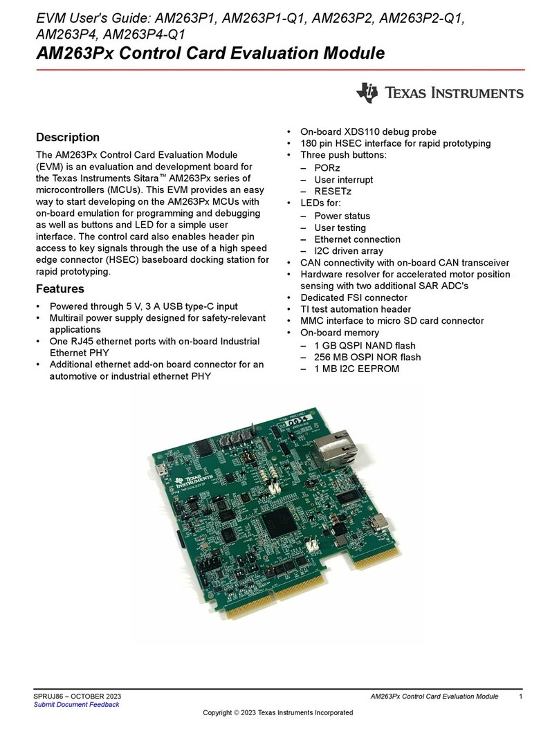
Texas Instruments AM263P Series User manual
Texas Instruments
Texas Instruments LM5066I EVM User manual

Texas Instruments
Texas Instruments UCC5390SCD User manual
Texas Instruments
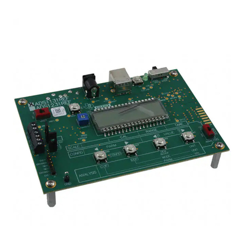
Texas Instruments ADS1131REF User manual
Texas Instruments
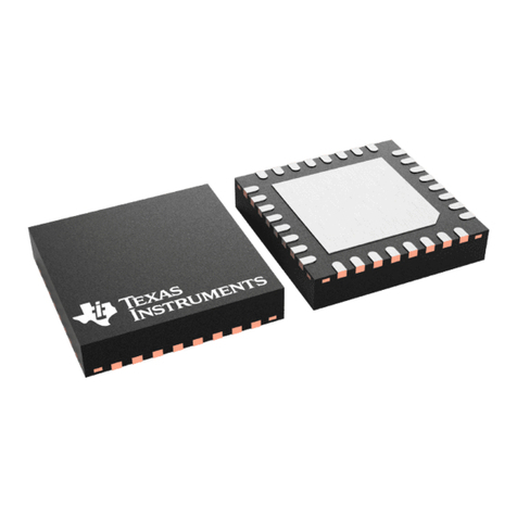
Texas Instruments TAS2559 User manual
Texas Instruments
Texas Instruments TRF7960A User manual
Texas Instruments
Texas Instruments TPA6120A2RGY EVM User manual
Popular Control Unit manuals by other brands

Festo
Festo Compact Performance CP-FB6-E Brief description

Elo TouchSystems
Elo TouchSystems DMS-SA19P-EXTME Quick installation guide

JS Automation
JS Automation MPC3034A user manual

JAUDT
JAUDT SW GII 6406 Series Translation of the original operating instructions

Spektrum
Spektrum Air Module System manual

BOC Edwards
BOC Edwards Q Series instruction manual

KHADAS
KHADAS BT Magic quick start

Etherma
Etherma eNEXHO-IL Assembly and operating instructions

PMFoundations
PMFoundations Attenuverter Assembly guide

GEA
GEA VARIVENT Operating instruction

Walther Systemtechnik
Walther Systemtechnik VMS-05 Assembly instructions

Altronix
Altronix LINQ8PD Installation and programming manual
