Texas Instruments SimpleLink CC2650 User manual
Other Texas Instruments Microcontroller manuals
Texas Instruments
Texas Instruments Hercules RM48 User manual

Texas Instruments
Texas Instruments TUSB3210 User manual
Texas Instruments
Texas Instruments CC3235 SimpleLink Series User manual
Texas Instruments
Texas Instruments Concerto F28M35 Series Product manual
Texas Instruments
Texas Instruments MSP430F6767 User manual
Texas Instruments
Texas Instruments OPT3002EVM User manual
Texas Instruments
Texas Instruments OMAP35 Series User manual
Texas Instruments
Texas Instruments TMS570LS3137 User manual
Texas Instruments
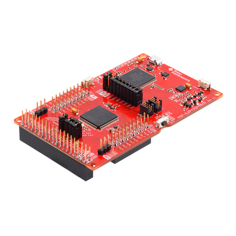
Texas Instruments MSP432P401R User manual
Texas Instruments
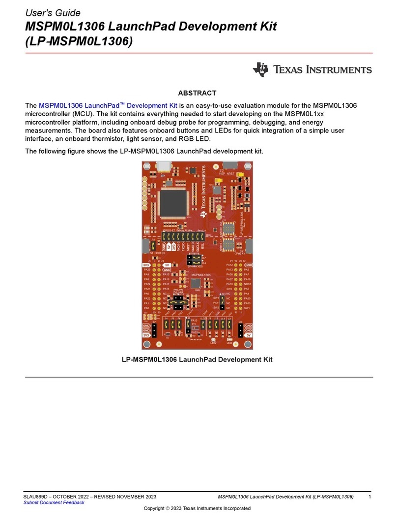
Texas Instruments MSPM0L1306 User manual
Texas Instruments
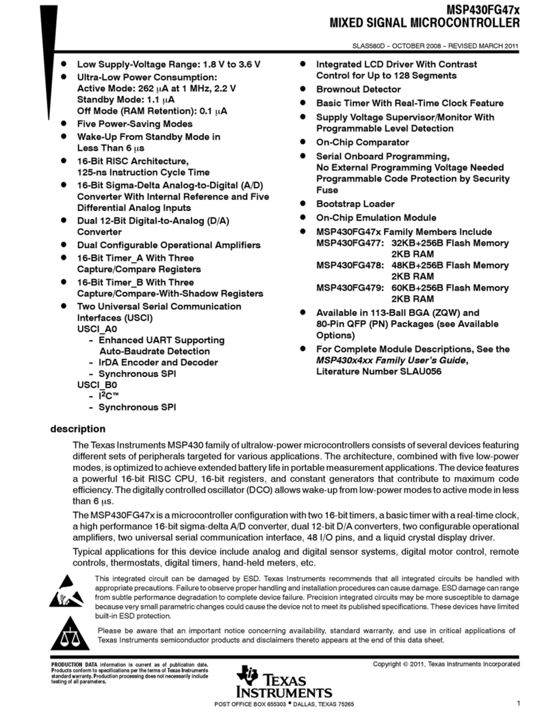
Texas Instruments MSP430FG47x User manual
Texas Instruments
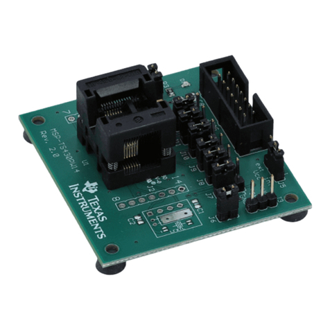
Texas Instruments MSP430 series User manual
Texas Instruments
Texas Instruments TMDXRM42HDK User manual
Texas Instruments
Texas Instruments TLC2543 User manual
Texas Instruments
Texas Instruments TMS320C6000 DSP Guide
Texas Instruments
Texas Instruments MSP430G2231 User manual
Texas Instruments
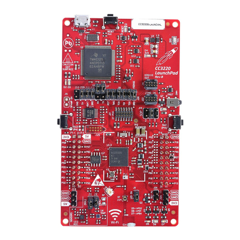
Texas Instruments CC3220 User manual
Texas Instruments
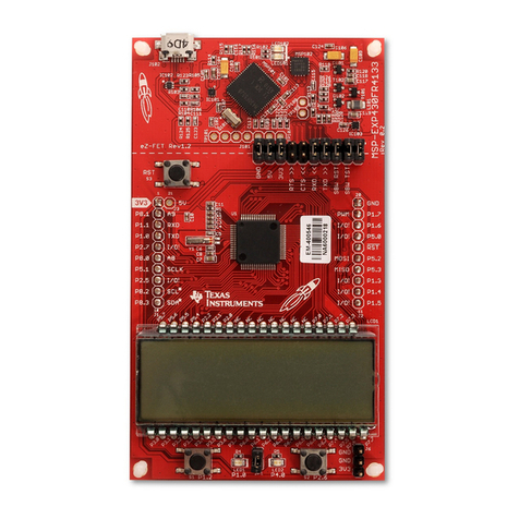
Texas Instruments LaunchPad MSP430FR4133 User manual
Texas Instruments
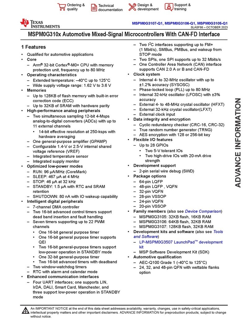
Texas Instruments MSPM0G310 Series User manual
Texas Instruments
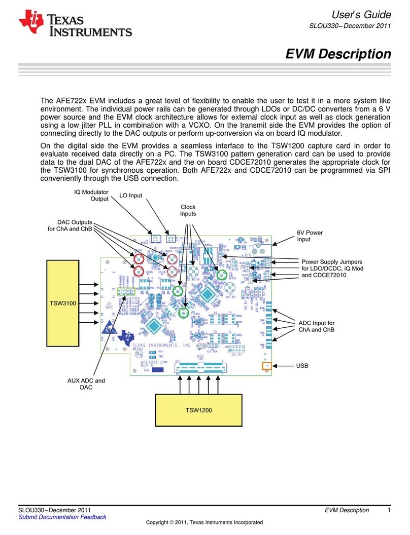
Texas Instruments AFE722 Series User manual
Popular Microcontroller manuals by other brands

Novatek
Novatek NT6861 manual

Espressif Systems
Espressif Systems ESP8266 SDK AT Instruction Set

Nuvoton
Nuvoton ISD61S00 ChipCorder Design guide

STMicrolectronics
STMicrolectronics ST7 Assembler Linker user manual

Lantronix
Lantronix Intrinsyc Open-Q 865XR SOM user guide

NEC
NEC 78GK0S/K 1+ Series Application note
