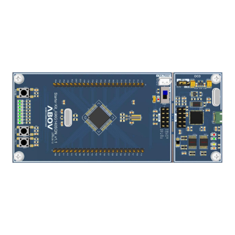
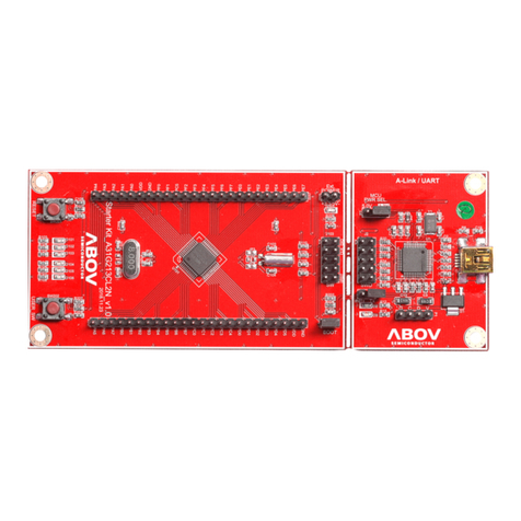
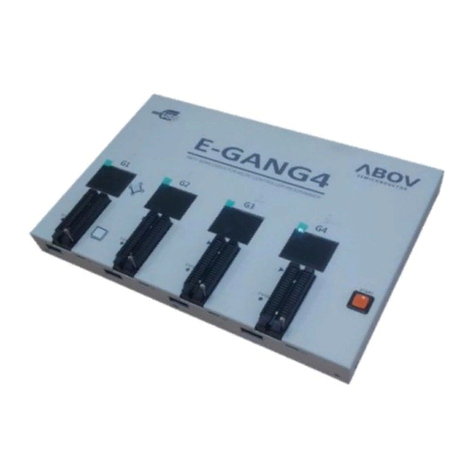
Abov MC96FR116C Series User manual

MC96FR116C
November, 2018 Rev.1.8 1
ABOV SEMICONDUCTOR Co., Ltd.
8-BIT MICROCONTROLLERS
MC96FR116C
User’s Manual (Rev.1.8)

MC96FR116C
2 November, 2018 Rev.1.8
REVISION HISTORY
REVISION 0.0 (August 6, 2013)
- Initial preliminary version
REVISION 0.1 (November 15, 2013)
7. ELECTRICAL CHARACTERISTICS
12.5 BOD mode
The initial value of BODR register is changed from 81Hto C9H.
REVISION 0.2 (December 3, 2013)
7.2 RECOMMENDED OPERATING CONDITION
7.4 BROWN OUT DETECTOR(BOD) CHARACTERISTICS
7.10 DC CHARACTERISTICS
REVISION 0.3 (December 22, 2013)
1.3 Ordering Information
REVISION 0.4 (January 24, 2014)
7.7 Internal RING Oscillator CHARACTERISTICS
7.9 Analog Comparator CHARACTERISTICS
7.11 DC CHARACTERISTICS
DC characteristics of REM_PP_OUT, REM_OD_OUT are added.
The max. current of stop mode is changed from 15uA to 10uA.
9.2.7 Register Map
The initial value of P0BPC is changed from 0x00 to 0xFF
The initial value of P1BPC is changed from 0x00 to 0xFB
9.2.10 PORT Miscellaneous
The definition of PMISC1 is changed.
13.9 Register Description
The BODLS of BODR and BOSDR is changed.
REVISION 0.5 (March 7, 2014)
7.5 RAM Data Retention CHARACTERISTICS
The parameter of “Data Retention Supply Current”is added.
7.6 FLASH CHARACTERISTICS
Flash write Supply Voltage: min. 1.6V min. 1.55V
Page Erase Time: typ. 2.5ms max. 2.5ms
Page Program Time: typ. 2.5ms max. 2.5ms
Program/Erase Cycle: typ. 10,000 cycles min. 10,000 cycles
Data Retention: typ. 10 years min. 10 years
7.12 AC CHARACTERISTICS
tIW: 2 tSYS 10ns
7.13 I2C CHARACTERISTICS

MC96FR116C
November, 2018 Rev.1.8 3
Timing characteristics is added.
7.14 USART CHARACTERISTICS
max. values of tLEAD, tLAG, tSIM, tSIS, tSOM, tSOS are removed.
16.1 FUSE Control register
The Definition of FUSE_CONF is added.
REVISION 1.0 (April 4, 2014)
- Initial version
REVISION 1.1 (April 16, 2014)
1.2 Features
On-Chip RC-Oscillator
12MHz ±1.0% @ -20 ~ +70℃(User Trim)
12MHz ±0.5% @ +15 ~ +45℃(User Trim)
Operating Voltage
VBODR ~ 3.6V (VDD)
VBODR ~ 4.0V (VDD_IR)
(Note. Min. voltage of FLASH write is 1.55V)
Registers are changed.
PMISC1 is changed
FLTEN, IRCC0[3] is added.
IRCC3 is added.
7.11 DC CHARACTERISTICS
IOL(VDD=3.3V) is changed from 18mA to 16mA.
7.12 AC CHARACTERISTICS
Minimum tIW is added.
Minimum tRST is added.
tREM_OD_R and tREM_OD_F are added.
11.6 IR Capture Control
“Figure 11-28 Block Diagram of IR Learning”is changed.
“Figure 11-29 Timing Diagram of IR Learning”is added.
REVISION 1.2 (May 23, 2014)
7.4 BROWN OUT DETECTOR(BOD) CHARACTERISTICS
The parameter of VHYS is added.
7.9 Analog Comparator CHARACTERISTICS
The parameters of IILD and IIHD are added.
7.11 DC CHARACTERISTICS
The parameters of VHYS and CIN are added.
IOH of VOH is updated.
VDD=3.3V; 7mA 6mA
IOHs of VOH_REM_PP are updated.
VDD=3.3V; 20mA 8.5mA
VDD=1.8V; 3.5mA 2.5mA

MC96FR116C
4 November, 2018 Rev.1.8
REVISION 1.3 (July 10, 2014)
11.6.4 Register Description
The comment of RSEL(IRCC0[2:0] register) is updated.
7.9 Analog Comparator CHARACTERISTICS
Recommended condition is added.
REVISION 1.4 (November 21, 2014)
1.3 Ordering Information
“7.3 POWER SEQUENCE CHARACTERISTICS”is added.
“12.8 Power Sequence”is added.
REVISION 1.5 (January 13, 2015)
1.2 Features
On-Chip RC-Oscillator
WLCSP
12MHz ±1.0% @ -20 ~ +70℃
12MHz ±0.5% @ +15 ~ +45℃
QFN
12MHz ±2.0% @ -20 ~ +70℃
12MHz ±1.0% @ +15 ~ +45℃
1.3 Ordering Information
3. PIN CONFIGURATION, 4. PACKAGE DIMENSION
The information of 16 QFN is added.
7.8 Internal RC Oscillator CHARACTERISTICS
The information of 16 QFN is added.
REVISION 1.6 (May 20, 2016)
11.10 I2C
I2C is added.
REVISION 1.7 (Jan. 12, 2018)
3. Add pin configurations. 20 SOP,
4. Add package dimension 20 SOP, 20 TSSOP
1.3 Ordering information are changed
MC96FR116C -> MC96FR116CUB, -> MC96FR116CDB
Device Nomenclature is added
1.4 Development Tools is added
REVISION 1.8 (November. 19, 2018)
1.4.3 Add OCD Port Operation
Remove 20 SOP PKG
4. Update package dimension 16WLCSP, 16QFN, 20 TSSOP

MC96FR116C
November, 2018 Rev.1.8 5
Table of Contents
REVISION HISTORY..........................................................................................................................................2
Table of Contents.................................................................................................................................................5
List of Figures.......................................................................................................................................................8
MC96FR116C.....................................................................................................................................................11
1. OVERVIEW.....................................................................................................................................................11
1.1 Description.................................................................................................................................................11
1.2 Features......................................................................................................................................................11
1.3 Ordering Information.................................................................................................................................12
1.4 Development Tools....................................................................................................................................14
2. BLOCK DIAGRAM.........................................................................................................................................19
3. PIN CONFIGURATIONS................................................................................................................................20
4. PACKAGE DIMENSION................................................................................................................................23
5. PIN DESCRIPTION.........................................................................................................................................26
6. PORT STRUCTURES .....................................................................................................................................27
6.1 General Purpose I/O Port...........................................................................................................................27
6.2 External Interrupt I/O Port.........................................................................................................................28
6.3 REM_PP_OUT Port ..................................................................................................................................29
6.4 REM_OD_OUT Port.................................................................................................................................29
7. ELECTRICAL CHARACTERISTICS.............................................................................................................30
7.1 Absolute Maximum Ratings ......................................................................................................................30
7.2 RECOMMENDED OPERATING CONDITION......................................................................................30
7.3 POWER SEQUENCE CHARACTERISTICS ..........................................................................................30
7.4 VOLTAGE DROPOUT CONVERTER(1.8V Internal regulator) CHARACTERISTICS........................31
7.5 BROWN OUT DETECTOR(BOD) CHARACTERISTICS .....................................................................31
7.6 RAM Data Retention CHARACTERISTICS............................................................................................31
7.7 FLASH CHARACTERISTICS .................................................................................................................31
7.8 Internal RC Oscillator CHARACTERISTICS...........................................................................................32
7.9 Internal RING Oscillator CHARACTERISTICS ......................................................................................32
7.10 Analog Comparator CHARACTERISTICS ............................................................................................32
7.11 POWER-ON RESET CHARACTERISTICS..........................................................................................33
7.12 DC CHARACTERISTICS.......................................................................................................................33
7.13 AC CHARACTERISTICS.......................................................................................................................34
7.14 I2C CHARACTERISTICS......................................................................................................................36
7.15 REM_PP_OUT PORT CHARACTERISTICS........................................................................................37
7.16 REM_OD_OUT PORT CHARACTERISTICS.......................................................................................38
7.17 TYPICAL CHARACTERISTICS ...........................................................................................................38
8. MEMORY........................................................................................................................................................39
8.1 Program Memory.......................................................................................................................................39
8.2 IRAM.........................................................................................................................................................40
8.3 XRAM .......................................................................................................................................................44
8.4 Registers ....................................................................................................................................................45
9. I/O PORTS .......................................................................................................................................................49
9.1 Introduction................................................................................................................................................49

MC96FR116C
6 November, 2018 Rev.1.8
9.2 Register Description...................................................................................................................................49
10. Interrupt Controller.........................................................................................................................................55
10.1 Overview..................................................................................................................................................55
10.2 External Interrupt.....................................................................................................................................56
10.3 Block Diagram.........................................................................................................................................57
10.4 Interrupt Vectors......................................................................................................................................58
10.5 Interrupt Sequence ...................................................................................................................................58
10.6 Effective time of Interrupt Request..........................................................................................................59
10.7 Multiple Interrupts ...................................................................................................................................60
10.8 Interrupt Service Procedure .....................................................................................................................61
10.9 Generation of Branch Address to Interrupt Service Routine(ISR)...........................................................61
10.10 Saving and Restoring General Purpose Registers..................................................................................62
10.11 Interrupt Timing.....................................................................................................................................63
10.12 Interrupt Registers..................................................................................................................................63
11. Peripheral Units..............................................................................................................................................70
11.1 Clock Generator.......................................................................................................................................70
11.2 Basic Interval Timer (BIT) ......................................................................................................................72
11.3 Watch Dog Timer (WDT)........................................................................................................................75
11.4 TIMER/PWM ..........................................................................................................................................77
11.5 Watch Timer with event capture function (WT)....................................................................................106
11.6 IR Capture Control (IRCC)....................................................................................................................112
11.7 Carrier Generator...................................................................................................................................116
11.8 Key Scan................................................................................................................................................124
11.9 UART ....................................................................................................................................................127
11.10 I2C........................................................................................................................................................141
12. POWER MANAGEMENT ..........................................................................................................................158
12.1 Overview................................................................................................................................................158
12.2 PERIPHERAL OPERATION IN SLEEP/STOP/BOD MODE.............................................................158
12.3 SLEEP mode..........................................................................................................................................158
12.4 STOP mode............................................................................................................................................159
12.5 BOD mode.............................................................................................................................................161
12.6 Register Map..........................................................................................................................................164
12.7 Register Description...............................................................................................................................164
12.8 Power Sequence.....................................................................................................................................164
13. RESET..........................................................................................................................................................165
13.1 Overview................................................................................................................................................165
13.2 Reset source...........................................................................................................................................165
13.3 Block Diagram.......................................................................................................................................165
13.4 Noise Canceller for External Reset Pin..................................................................................................166
13.5 Power-On-RESET .................................................................................................................................166
13.6 External RESETB Input.........................................................................................................................168
13.7 Brown Out Detector...............................................................................................................................169
13.8 Register Map..........................................................................................................................................171
13.9 Register Description...............................................................................................................................171
14. On-chip Debug System.................................................................................................................................174
14.1 Overview................................................................................................................................................174
14.2 Two-pin external interface.....................................................................................................................175
15. FLASH Memory Controller .........................................................................................................................179
MC96FR116C
November, 2018 Rev.1.8 7
15.1 Overview................................................................................................................................................179
15.2 Boot Area...............................................................................................................................................179
15.3 Register Map..........................................................................................................................................180
15.4 Register Description...............................................................................................................................181
15.5 Memory map..........................................................................................................................................187
15.6 Serial In-System Program Mode............................................................................................................188
15.7 Security..................................................................................................................................................192
16. FUSE ............................................................................................................................................................193
16.1 FUSE Control Register ..........................................................................................................................193
17. APPENDIX ..................................................................................................................................................194

MC96FR116C
8 November, 2018 Rev.1.8
List of Figures
Figure 1-1 Device Nomenclature.........................................................................................................13
Figure 1-2 OCD Software and Connector.............................................................................................14
Figure 1-3 OCD Mode Sequence..........................................................................................................15
Figure 1-4 OCD Interface Circuit.........................................................................................................16
Figure 1-5 E-PGM+..............................................................................................................................17
Figure 1-6 PGMPlusLC-II....................................................................................................................18
Figure 1-7 Gang programmer ...............................................................................................................18
Figure 2-1 Block Diagram of MC96FR116C .......................................................................................19
Figure 3-1 16 WLCSP Pin-out of MC96FR116CW.............................................................................20
Figure 3-2 16 QFN Pin-out of MC96FR116CU..................................................................................21
Figure 3-3 20 TSSOP Pin-out of MC96FR116CR ..............................................................................22
Figure 4-1 PKG DIMENSION (16 WLCSP) .......................................................................................23
Figure 4-2 PKG DIMENSION (16 QFN).............................................................................................24
Figure 4-3 PKG DIMENSION (20 TSSOP).........................................................................................25
Figure 6-1 General I/O..........................................................................................................................27
Figure 6-2 I/O with external interrupt function ....................................................................................28
Figure 7-1 AC Timing ..........................................................................................................................35
Figure 7-2 Timing diagram of I2C ........................................................................................................36
Figure 7-3 IOL vs VOL for REM_PP_OUT ........................................................................................37
Figure 7-4 IOH vs VOH for REM_PP_OUT........................................................................................37
Figure 7-5 Characteristics for REM_OD_OUT....................................................................................38
Figure 8-1 Program Memory................................................................................................................39
Figure 8-2 DATA MEMORY (IRAM).................................................................................................40
Figure 8-3 Lower 128 Byte of IRAM...................................................................................................41
Figure 8-4 PSW Register......................................................................................................................43
Figure 8-5 DATA MEMORY (XRAM)...............................................................................................44
Figure 10-1 External Interrupt trigger condition...................................................................................56
Figure 10-2 Block Diagram of Interrupt Controller..............................................................................57
Figure 10-3 Sequence of Interrupt handling .........................................................................................59
Figure 10-4 Effective time of interrupt request after setting IEx registers ...........................................60
Figure 10-5 Accept of another interrupt request in interrupt service routine........................................60
Figure 10-6 Interrupt Request and Service Procedure..........................................................................61
Figure 10-7 Generating branch address to BIT interrupt service routine from vector table .................62
Figure 10-8 Processing General registers while an interrupt is serviced ..............................................62
Figure 10-9 Timing chart for Interrupt Accept and Branch Address Generation .................................63
Figure 11-1 Block Diagram of Clock Generator ..................................................................................70
Figure 11-2 Block Diagram of BIT ......................................................................................................73
Figure 11-3 Block Diagram..................................................................................................................75
Figure 11-4 WDT Interrupt and Reset Timing .....................................................................................76
Figure 11-5 Block Diagram of Timer 0,1 in 8-bit timer/counter mode ................................................79
Figure 11-6 Interrupt Period of Timer 0, 1 ...........................................................................................80
Figure 11-7 Counter Operation of Timer 0, 1.......................................................................................80

MC96FR116C
November, 2018 Rev.1.8 9
Figure 11-8 Block Diagram of Timer 0, 1 in 16-bit Timer/ Counter mode ..........................................81
Figure 11-9 Block Diagram of Timer 0, 1 in 8-bit Capture mode ........................................................83
Figure 11-10 Timer 0,1 Operation in 8-bit Input Capture Mode ..........................................................84
Figure 11-11 Example of Capture Interval Calculation in 8-bit Input Capture Mode..........................84
Figure 11-12 Block Diagram of Timer 0, 1 in 16-bit Capture Mode....................................................85
Figure 11-13 Block Diagram of Timer 1 in PWM mode......................................................................86
Figure 11-14 Example of PWM Waveform (In case frequency of SCLK(=fSCLK) is 4MHz)...............87
Figure 11-15 Behavior of waveform when changing period (In case fSCLK is 4MHz)..........................87
Figure 11-16 Block Diagram of 16-bit Timer 2 in Output Compare or Event Counter Mode .............92
Figure 11-17 Block Diagram of Timer 2 in Capture Mode ..................................................................92
Figure 11-18 Block Diagram of Timer 2 in Carrier Counting Mode....................................................93
Figure 11-19 Block Diagram of Timer 3 in Output Compare or Event Counter Mode........................97
Figure 11-20 Block Diagram of Timer 3 in Capture Mode ..................................................................98
Figure 11-21 Block Diagram of Timer 3 in Carrier Counting Mode....................................................99
Figure 11-22 Block Diagram of Timer 3 in PWM Mode ...................................................................100
Figure 11-23 Example of PWM waveform (In case of fSCLK=4MHz) ................................................101
Figure 11-24 Block Diagram of Watch Timer in Normal mode.........................................................106
Figure 11-25 Block Diagram of Watch Timer in IR capture mode ....................................................107
Figure 11-26 Timing Diagram of Watch Timer in IR capture mode..................................................107
Figure 11-27 Block Diagram of IR Capture function .........................................................................112
Figure 11-28 Block Diagram of IR Learning......................................................................................112
Figure 11-29 Timing Diagram of IR Learning ...................................................................................113
Figure 11-30 Block Diagram of Carrier Generator.............................................................................116
Figure 11-31 Period of Carrier signal and Remote data pulse ............................................................120
Figure 11-32 REMOUT by CRF & ROB (In case of CEN=1, RDPE=1) ..........................................121
Figure 11-33 REMOUT by ROB only (In case of CEN=0, RDPE=1)...............................................122
Figure 11-34 REMOUT by RODR.....................................................................................................122
Figure 11-35 Block Diagram of KEYSCAN module .........................................................................124
Figure 11-36 The Block Diagram of UART.......................................................................................128
Figure 11-37 The Block Diagram of UART.......................................................................................128
Figure 11-38 The Block Diagram of Clock Generation......................................................................129
Figure 11-39 frame format..................................................................................................................130
Figure 11-40 Start Bit Sampling.........................................................................................................133
Figure 11-41 The Sampling of Data and Parity Bit ............................................................................134
Figure 11-42 Stop Bit Sampling and Next Start Bit Sampling ...........................................................134
Figure 11-43 I2C Block Diagram........................................................................................................141
Figure 11-44 Bit Transfer on the I2C-Bus...........................................................................................142
Figure 11-45 START and STOP Condition........................................................................................142
Figure 11-46 STOP or Repeated START Condition ..........................................................................143
Figure 11-47 Acknowledge on the I2C-Bus........................................................................................143
Figure 11-48 Clock Synchronization during Arbitration Procedure...................................................144
Figure 11-49 Arbitration Procedure of Two Masters..........................................................................144
Figure 11-50 Formats and States in the Master Transmitter Mode.....................................................147
Figure 11-51 Formats and States in the Master Receiver Mode.........................................................149
Figure 11-52 Formats and States in the Slave Transmitter Mode.......................................................151

MC96FR116C
10 November, 2018 Rev.1.8
Figure 11-53 Formats and States in the Slave Receiver Mode ...........................................................153
Figure 12-1 Wake-up from SLEEP mode by an interrupt ..................................................................159
Figure 12-2 SLEEP mode release by an external reset.......................................................................159
Figure 12-3 Wake-up from STOP mode by an interrupt ....................................................................160
Figure 12-4 STOP mode release by an external reset.........................................................................160
Figure 12-5 BOD mode during normal mode.....................................................................................162
Figure 12-6 BOD mode during stop mode..........................................................................................163
Figure 12-7 Power Sequence ..............................................................................................................164
Figure 13-1 Block Diagram of Reset Circuit......................................................................................165
Figure 13-2 Noise Cancelling of External Reset Pin ..........................................................................166
Figure 13-3 Reset Release Timing when Power is supplied (VDD Rises Rapidly) ...........................166
Figure 13-4 Reset Release Timing when Power is supplied (VDD Rises Slowly).............................167
Figure 13-5 Fuse Configuration Value Read Timing after Power On ................................................167
Figure 13-6 Operation according to Power Level...............................................................................168
Figure 13-7 Reset procedure due to external reset input.....................................................................169
Figure 13-8 Block Diagram of BOD ..................................................................................................170
Figure 13-9 Configuration value read timing when BOD RESET is asserted....................................171
Figure 14-1 Block Diagram of On-Chip Debug System.....................................................................175
Figure 14-2 10-bit transmission packets.............................................................................................176
Figure 14-3 Data transfer on the twin bus...........................................................................................176
Figure 14-4 Bit transfer on the serial bus............................................................................................177
Figure 14-5 Start and stop condition...................................................................................................177
Figure 14-6 Acknowledge by receiver................................................................................................177
Figure 14-7 Clock synchronization during wait procedure.................................................................178
Figure 14-8 Wire connection for serial communication .....................................................................178
Figure 15-1 Program Memory Address Space....................................................................................180
Figure 15-2 FLASH Memory Map.....................................................................................................187
Figure 15-3 FLASH Memory Address generation .............................................................................187

MC96FR116C
November, 2018 Rev.1.8 11
MC96FR116C
CMOS 8-bit Flash Microcontroller : UR
1. OVERVIEW
1.1 Description
The MC96FR116C is an advanced 8-bit microcontroller based on CMOS process with 16K Bytes of
Flash. This is a powerful device which provides a highly flexible and cost effective solution to many
embedded control applications.
The MC96FR116C provides the following features : 16K Bytes of embedded FLASH ROMNOTE1, 2048
Bytes of XRAM, 256 Bytes of IRAM, 8/16-bit Timer/Counter, WDT, WT, 10-bit PWM, UART, I2C,
Carrier Generator, 8-bit Basic Interval Timer, Watch Timer and Clock control circuit. It also provides
one dedicated output pin which has large current drivability specialized for remote control application.
Additionally, the MC96FR116C supports power saving modes to reduce power consumption.
NOTE1 In this document, the ROM means non-volatile memory which is read-writable.
Device Name
FLASH size
IRAM
XRAM
I/O PORT
Package
MC96FR116C
16KB
256B
2048B
12
16 WLCSP
16 QFN
20 TSSOP
1.2 Features
•CPU
8-bit CISC Core (8051 Compatible, 2 clocks
per cycle)
•16K Bytes On-chip FLASH
Endurance : 10,000 times
Retention : 10 years
•XRAM
2048 Bytes
•IRAM
256 Bytes
•General Purpose I/O
12 Ports (P0[5:0],P1[5:0])
•One Basic Interval Timer
•Timer / Counter
8-bit×2ch(16-bit×1ch) + 16-bit×2ch
•10-bit PWM (Using Timer0,1)
•16-bit PWM (using Timer3)
•One Watch Dog Timer
•One Watch Timer
•One UART
•One I2C
•One Carrier Generator
•Interrupt Sources
External : 6
UART: 1
I2C: 1
Carrier Generator : 1
WDT :1
WT : 1
BIT :1
Timer0,1,2,3 : 4
FLASH : 1

MC96FR116C
12 November, 2018 Rev.1.8
Key scan: 1
Pin change(P0[5:0]):1
•Flash secure protection
•Analog Comparator for IR learning
•Power On Reset
•Programmable Brown-Out Detector
Reset: 1.52V
Interrupt or flag: 1.63, 1.8, 2.0, 2.2, 2.4V
•Minimum Instruction Execution Time
200ns (@10MHz, 1 Cycle NOP Instruction)
•Power down mode
SLEEP, STOP mode
•On-Chip IR Transistor
•On-Chip RC-Oscillator
. WLCSP
12MHz ±1.0% @ -20 ~ +70℃(User Trim)
12MHz ±0.5% @ +15 ~ +45℃(User Trim)
. 16QFN / 20TSSOP
12MHz ±2.0% @ -20 ~ +70℃(User Trim)
12MHz ±1.0% @ +15 ~ +45℃(User Trim)
•Operating Frequency
1 ~ 12MHz (X-Tal oscillator)
12, 8, 6, 4MHz ( Internal RC oscillator)
•Operating Voltage
VBODR ~ 3.6V (VDD)
VBODR ~ 4.0V (VDD_IR)
(Note. Min. voltage of FLASH write is 1.55V)
•Operating Temperature
•-20 ~ +70℃
•PKG Type
16 WLCSP
16 QFN
Available Pb free package
1.3 Ordering Information
Device name
ROM size
IRAM size
XRAM size
Package
MC96FR116CR
16KB FLASH
256B
2048B
20 TSSOP
MC96FR116CU
16 QFN
MC96FR116CW
16 WLCSP
Table 1-1 Ordering Information

MC96FR116C
November, 2018 Rev.1.8 13
1.3.1 Device Nomenclature
Device nomenclature
MC96FR116Cx Family Name
Package type
RoHS
Packing
MC96FR116Cx RN(T)
UQFN
RTSSOP
Halogen Free
(T) Tape & Reel
B
WWLCSP
Figure 1-1 Device Nomenclature

MC96FR116C
14 November, 2018 Rev.1.8
1.4 Development Tools
1.4.1 Compiler
ABOV semiconductor does not provide any compiler for MC96FR116C. As the CPU core of
MC96FR116C is Mentor 8051, you can use all kinds of third party’s standard 8051 compiler.
1.4.2 OCD emulator and debugger
OCD(On Chip Debugger) program is a debugging software for ABOV semiconductor’s 8051 MCU
series. OCD uses only two lines to download a user code, to read and modify the internal memory or
SFR(Special Function Register)s. And also OCD controls MCU’s internal debugging logic, which
means OCD controls emulation, step run, monitoring, etc.
OCD debugger program works on Microsoft-Windows 7, NT, 2000, XP, Vista(32-bit) operating system.
If you want to see details more, please refer to OCD debugger manual. You can download debugger
S/W and manual from out web-site.
The connecting pins between PC and MCU is as follows :
- DSCL (P1[0] of MC96FR116C)
- DSDA (P1[1] of MC96FR116C)
2. VDD
4. GND
6. Serial Clock (DSCL)
8. Serial Data (DSDA)
Figure 1-2 OCD Software and Connector

MC96FR116C
November, 2018 Rev.1.8 15
1.4.3 OCD Port Operation
Internal nPOR
Configure Read
Internal RESETb
12 ms (± 20%) @ Internal Ring OSC
LVI RESETB
orLVR RESETB
16 ms (± 20%) @ Internal Ring OSC
DSCL
DSDA
Test Mode
Control Reset
TEST_MODE
(OCD Mode)
The OCD port is used for flash program writing and device debugging. The device has a section that
determines whether to use it in that mode of POR. This is done when the internal reset is cleared and
waiting to clear Configure Read and Internal Reset. If the internal reset is cleared and DSCL and
DSDA wait for a period of time from internal pull-up 'high' to 'low', the internal controller for entering
test mode is initialized. Then, when DSCA and DSCA appointed communication, the test mode is
entered.
As described above, OCD port is a port for special purpose. Even if it is used as Normal GPIO in
User Program, it is necessary to limit the state to prevent malfunction during POR. Therefore, it is
recommended to connect Pull-up Resistor to the outside of OCD Port and to fix OCD Port input to
VDD / GND at POR. If it is difficult to apply pull-up on the circuit, install at least 0.1uf bypass capacitor
to prevent Floating state at POR. However, if you install a bypass cap, you can not use on board
writing and OCD Debugger.
Figure 1-3 OCD Mode Sequence

MC96FR116C
16 November, 2018 Rev.1.8
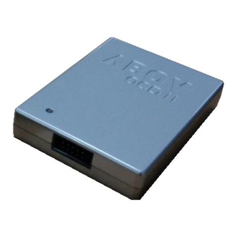
E-PGM+, PGM Plus LC2, E-PGM+ Gang4/6
DSCL(I)
DSDA(I/O)
VDD
VSS
R2 (0 ~ 200 )
R2 (0 ~ 200 )
To application circuit
R1
(10k )
R1
(10k )
C1
(0.1uf)
1.4.4 Programmer
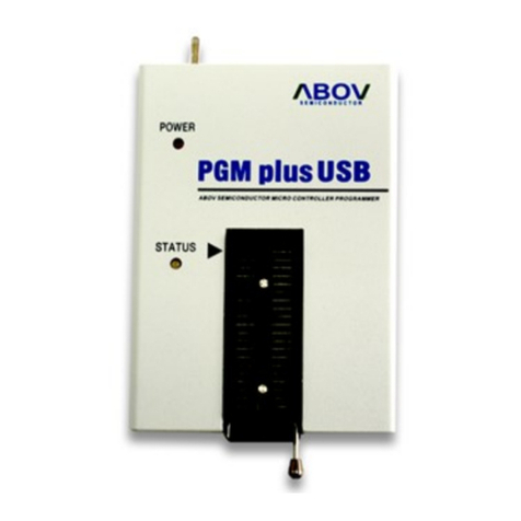
To program or download user code into the ROM of MC96FR116C, ABOV semiconductor provides
several tools. As a single programmer which can program only one chip at a time, there are E-PGM+
and PGMPlusLC-II. On the other hand, you can program multi-chips at a time by using a gang
programmer. Gang programmer, E-GANG6, can program up to 6 devices simultaneously.
Figure 1-4 OCD Interface Circuit

MC96FR116C
November, 2018 Rev.1.8 17
1.4.4.1 E-PGM+
E-PGM+ is a single write tool for ABOV MCUs.
Features :
Support ABOV / ADAM devices
2~5 times faster than S-PGM+
Main controller : 32 bit MCU @72MHz
Buffer memory : 1MB
1.4.4.2 PGMPlusLC-II
PGMPlusLC-II is for ISP (In System Programming). It is used to program or erase the MCU which is
already mounted on the target board using 10pin cable.
Features :
PGMPlusLC-II is low cost writing tool
USB interface is supported
No need for USB driver installation
Connect to the external power adaptor (5V@2A)
Fast 32-bit Cortex-M3 MCU is used
Support high voltage up to max 18V
PGMPlusLC-II is based on PC environment
PGMPlusLC-II is faster than PGMplusLC
Transmission speed of 64KB/s
1. MCU RX
2. VDD
3. MCU TX
4. GND
5. Run Flag or Boot Pin
6. Serial Clock (DSCL)
7. GND
8. Serial Data (DSDA)
9. N/A
10. VPP or Reset Pin
Enter Key Connector.
To connect with the auto-
handler
Power DC 9 ~ 15V
For ISP (In-System-Programming)
For Barcode reader
Figure 1-5 E-PGM+

MC96FR116C
18 November, 2018 Rev.1.8
1.4.4.3 E-GANG4(6)
The gang programmer, E-GANG4/(6) can program maximum4(6) MCUs at a time. So it is mainly used
in mass production line. As gang programmer is standalone type, it does not require host PC.
2. VDD
4. GND
6. Serial Clock (DSCL)
8. Serial Data (DSDA)
Figure 1-6 PGMPlusLC-II
Figure 1-7 Gang programmer

MC96FR116C
November, 2018 Rev.1.8 19
2. BLOCK DIAGRAM
PIN
Type
Option
Remarks
P15
I/O
RESETB
FUSE Control
P0
PORT
AMP /
IR Control
TIMER
&
PWM
INTERRUPT
CONTROLLER
P1
PORT
BIT
CLOCK /
SYSTEM
CONTROL
On-Chip
Debug
M8051
CORE
RAM
(2048B + 256B)
FLASH
(16KB)
Power On
Reset
Brown Out
Detector
CARRIER
GENERATOR
P03/T1/PWM1
P02/EC0
P03/T0
P01/T2
P05/PWM3
P00/INT0
P01/INT1
P02/INT2
P03/INT3
P04/INT4
P05/INT5
P05~P00
P15~P10
Voltage Down
Converter
P13/XIN
P14/XOUT
RESETB/P15
P10/DSCL
P11/DSDA
VDD
VSS
UART
WT
REM_OD_OUT
/SENSOR
P04/RXD0
P05/TXD0
P00/EC2
P04/EC3
WDT
REM_OD_OUT
INT-RC OSC
12MHz
INT-RING OSC
1MHz
I2C
P03/SDA
P02/SCL
Figure 2-1 Block Diagram of MC96FR116C
P12/REM_PP_OUT

MC96FR116C
20 November, 2018 Rev.1.8
3. PIN CONFIGURATIONS
16 WLCSP (MC96FR116C)
A2A1 A3 A4
B2B1 B3 B4
C2C1 C3 C4
1 2 3 4
A P11/DSDA VDD VDD_IR VSS
B P10/DSCL REMOUT_PP/P12 REMOUT_OD P13/XIN
C P05/INT5/TXD P03/INT3/SDA P14/XOUT P15/RESETB
D P04/INT4/RXD P02/INT2/SCL P01/INT1 P00/INT0
16 WLCSP 1.6 Typ.
1.6 Typ.
0.4 Typ.
D2D1 D3 D4
Figure 3-1 16 WLCSP Pin-out of MC96FR116CW
This manual suits for next models
3
Table of contents
Other Abov Microcontroller manuals

Abov
Abov MC96FR364B User manual

Abov
Abov MC95FG0128A User manual

Abov
Abov MC97F2664 User manual

Abov
Abov A96G140 User manual

Abov
Abov MC96F6432S Series User manual

Abov
Abov A96T418GDN User manual

Abov
Abov MC80F0304 User manual

Abov
Abov MC96F6432A User manual

Abov
Abov EW8051 User manual

Abov
Abov AC33M8128L User manual

Abov
Abov MC95FG208 Series User manual

Abov
Abov A31G213CL2N User manual

Abov
Abov MC97F6108A User manual

Abov
Abov MC97F60128 User manual

Abov
Abov A96G150 User manual

Abov
Abov A96G140 User manual

Abov
Abov 8-bit MCU User manual

Abov
Abov MC96F8204 Series User manual

Abov
Abov A96G140 User manual

Abov
Abov MC96F6432 Series User manual