User’s Guide
DRV8317HEVM User's Guide
ABSTRACT
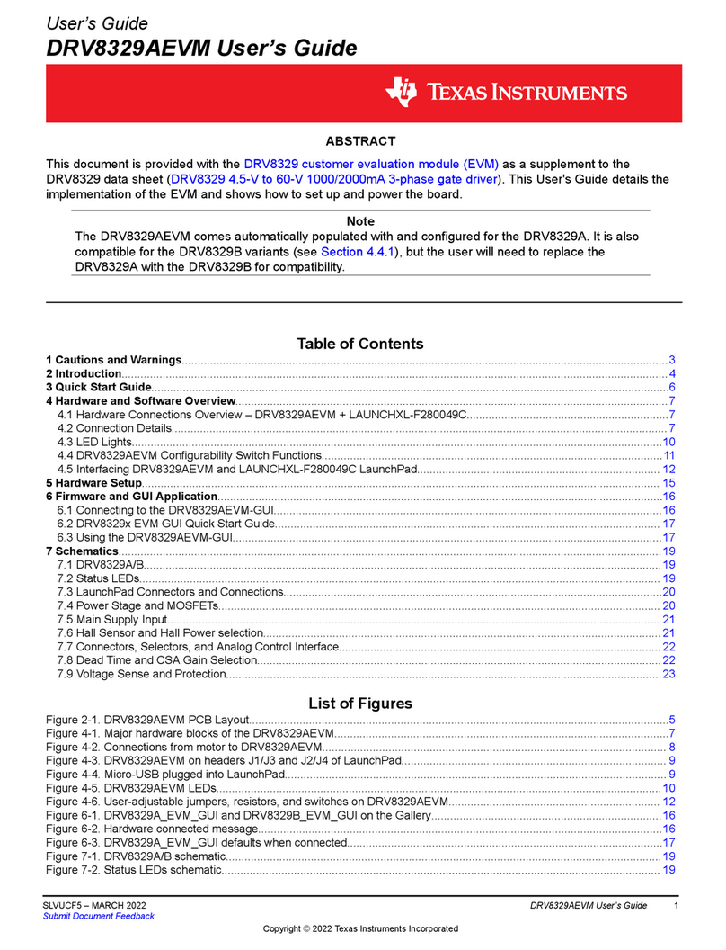
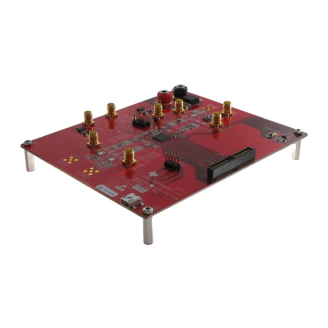
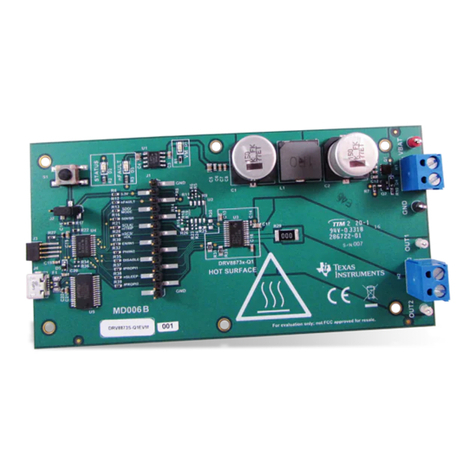
This document is provided with the DRV8317HEVM customer evaluation module (EVM) to evaluate the
DRV8317 4.5-V to 20-V Three-Phase Smart Gate Driver. This User's Guide details the implementation of the
EVM and shows how to set up and power the board with the LAUNCHXL-F280049C (C2000 Piccolo MCU
F280049C LaunchPad™ development kit).
Note
The DRV8317HEVM comes automatically populated with and configured for the DRV8317H hardware
device. It is also compatible for the DRV8317S variant, but the user will need to modify the board to
make it compatible for the SPI variant (see Section 4.4).
Table of Contents
1 Cautions and Warnings..........................................................................................................................................................2
2 Introduction.............................................................................................................................................................................3
3 Quick Start Guide....................................................................................................................................................................4
4 Hardware and Software Overview.........................................................................................................................................5
4.1 Hardware Connections Overview – DRV8317HEVM + LAUNCHXL-F280049C............................................................... 5
4.2 Connection Details............................................................................................................................................................. 5
4.3 LED Lights..........................................................................................................................................................................7
4.4 DRV8317HEVM Configurability – Jumpers and Resistors.................................................................................................8
5 Hardware Setup.................................................................................................................................................................... 14
6 Firmware and GUI Application.............................................................................................................................................15
6.1 C2000 InstaSPIN Universal GUI...................................................................................................................................... 15
6.2 Motor Identification...........................................................................................................................................................15
6.3 Sensorless-FOC Commutation........................................................................................................................................ 16
6.4 Torque Control, Speed Control, and Advanced Modulation Techniques..........................................................................17
6.5 SPI Communication (DRV8317S only).............................................................................................................................17
7 Schematics............................................................................................................................................................................19
7.1 Main Supply..................................................................................................................................................................... 19
7.2 DRV8317H/S....................................................................................................................................................................20
7.3 3.3V Buck Regulator and VREF.......................................................................................................................................21
7.5 LaunchPad Connections.................................................................................................................................................. 22
7.6 Connectors & Interface.................................................................................................................................................... 22
7.7 Status LEDs, Voltage Sense, and Protection...................................................................................................................23
8 Revision History................................................................................................................................................................... 23
Trademarks
All trademarks are the property of their respective owners.
www.ti.com Table of Contents
SLVUCL3 – DECEMBER 2022
Submit Document Feedback
DRV8317HEVM User's Guide 1
Copyright © 2022 Texas Instruments Incorporated
