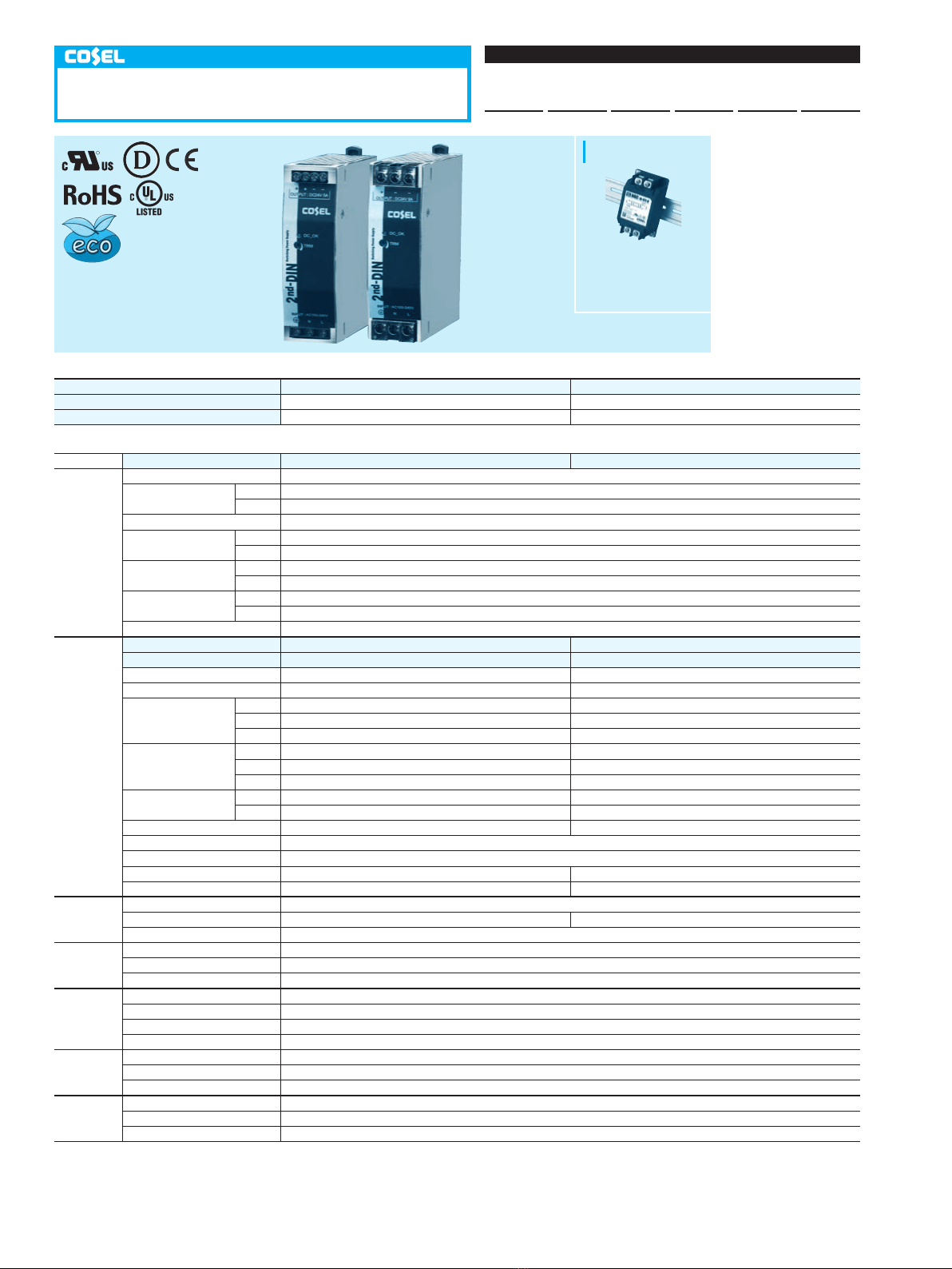
KL-2
KLEA/KLNA120F
AC-DC Power Supplies DIN Rail Type
KLOA 120 F -OO -O
Ordering information
1
Series name
KLE : Euro Style I/O Terminals
KLN
: Barrier Blocks Style
I/O Terminals
2
Single output
3
Output wattage
4
Universal input
5
Output voltage
6
Option
C
: with Coating
N2
:
Screw mounting
R
1 2 3 4 5 6
MODEL KLEA/KLNA120F-24 KLEA/KLNA120F-48
MAX OUTPUT WATTAGE[W] 120 120
DC OUTPUT 24V 5A 48V 2.5A
SPECIFICATIONS
MODEL KLEA/KLNA120F-24 KLEA/KLNA120F-48
INPUT
VOLTAGE[V]
AC85 - 264 1
f
(Refer to
“
Derating
”
)
*
9
CURRENT[A]
ACIN 115V
1.2typ
ACIN 230V
0.6typ
FREQUENCY[Hz]
50 / 60 (45 - 66)
EFFICIENCY[%]
ACIN 115V
86.5typ
ACIN 230V
88.0typ
POWER FACTOR
ACIN 115V
0.98typ
ACIN 230V
0.90typ
INRUSH CURRENT[A]
*
1
ACIN 115V
20typ (Io=100%)(at cold start Ta=25
C
)
ACIN 230V
40typ (Io=100%)(at cold start Ta=25
C
)
LEAKAGE CURRENT[mA]
0.45 / 0.75max (ACIN 100V / 240V 60Hz, Io=100%, According to IEC60950-1 and DEN-AN)
OUTPUT
VOLTAGE[V]
24 48
CURRENT[A]
5 2.5
LINE REGULATION[mV]
*
2
96max (Io=30-100%)
*
8
192max (Io=30-100%)
*
8
LOAD REGULATION[mV]
*
2
150max (Io=30-100%)
*
8
300max (Io=30-100%)
*
8
RIPPLE[mVp-p]
*
3
0 to +70C
150max 150max
-20 - 0C
240max 240max
Io=0 - 30%
500max 650max
RIPPLE NOISE[mVp-p]
*
3
0 to +70C
180max 180max
-20 - 0C
300max 300max
Io=0 - 30%
500max 650max
TEMPERATURE REGULATION[mV]
0 to +70C
240max 480max
-20 to +70C
290max 600max
DRIFT[mV]
*
4
96max 192max
START-UP TIME[ms]
500typ (ACIN 115V, Io=100%)
HOLD-UP TIME[ms]
20typ (ACIN 115V, Io=100%)
OUTPUT VOLTAGE ADJUSTMENT RANGE[V]
21.60 to 26.40 43.20 to 52.80
OUTPUT VOLTAGE SETTING[V]
24.00 to 24.96 48.00 to 49.92
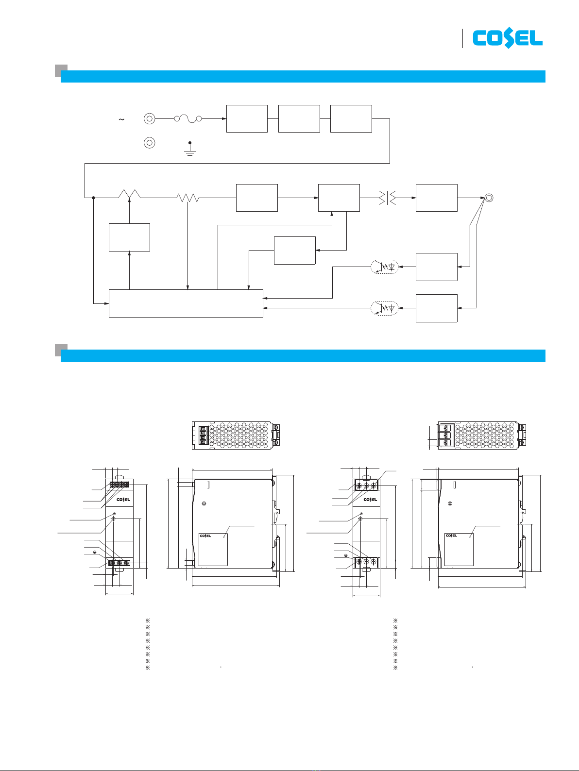
PROTECTION
CIRCUIT AND
OTHERS
OVERCURRENT PROTECTION
Works over 105% of rating and recovers automatically
OVERVOLTAGE PROTECTION[V]
27.60 to 33.60 54.00 to 67.20
DC_OK LAMP
LED (Green)
ISOLATION
INPUT-OUTPUT
AC3,000V 1minute, Cutoff current = 10mA, DC500V 50M
W
min
(
At Room Temperature
)
INPUT-PE
AC2,000V 1minute, Cutoff current = 10mA, DC500V 50M
W
min
(
At Room Temperature
)
OUTPUT-PE
AC500V 1minute, Cutoff current = 100mA, DC500V 50M
W
min
(
At Room Temperature
)
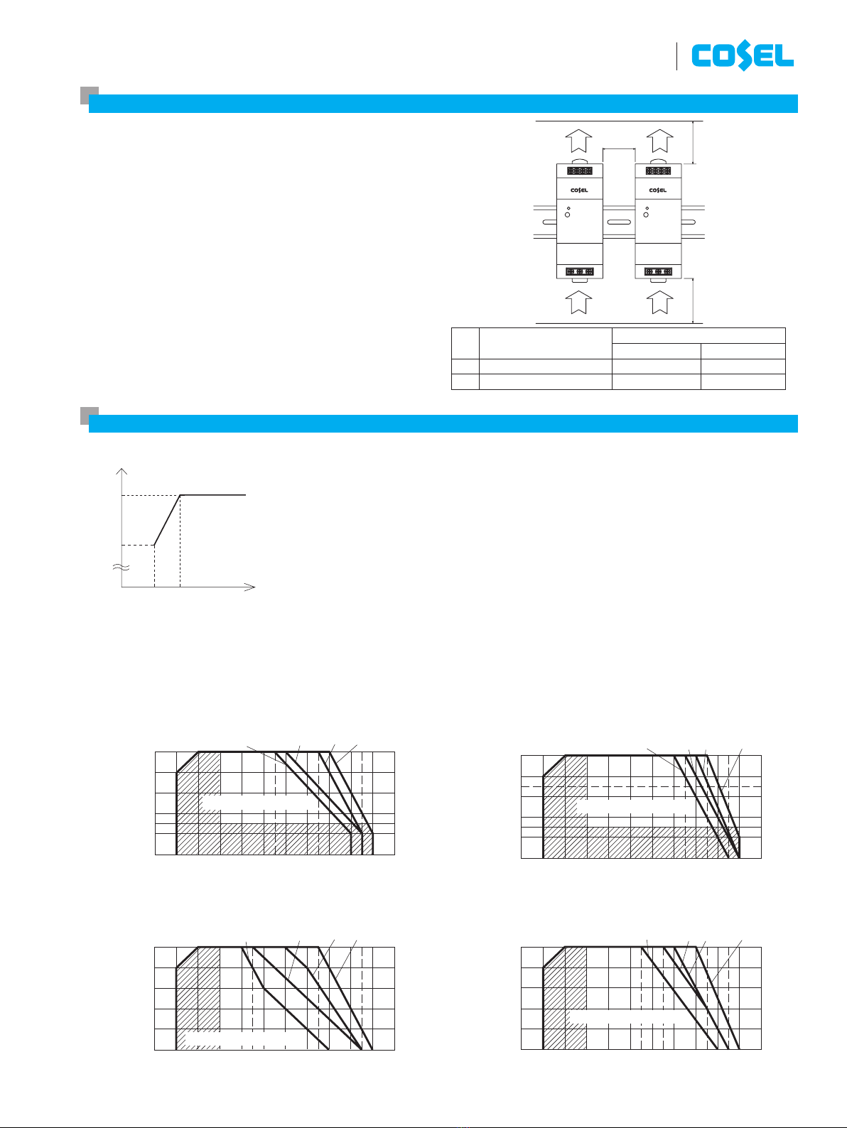
ENVIRONMENT
OPERATING TEMP.,HUMID.AND ALTITUDE
-20 to +70
C
, 20 - 90%RH (Non condensing), Type tested for -40
C
start-up (Refer to
“
Derating
”
)
STORAGE TEMP.,HUMID.AND ALTITUDE
-30 to +85
C
, 20 - 90%RH (Non condensing)
VIBRATION
*
7
10 - 55Hz, 19.6m/s
2
(2G), 3minutes period, 60 minutes along Z axis (Non operating, mounted on DIN Rail)
IMPACT
196.1m/s
2
(20G), 11ms, once each X, Y and Z axis (Packing state)
SAFETY AND
NOISE
REGULATIONS
AGENCY APPROVALS
UL60950-1, C-UL (CSA60950-1), EN60950-1, UL508, Complies with DEN-AN
CONDUCTED NOISE
Complies with FCC-B, VCCI-B, CISPR22-B, EN55011-B, EN55022-B
HARMONIC ATTENUATOR
Complies with IEC61000-3-2
(
Class A)
*
5
OTHERS
CASE SIZE
*
6
38
X
124
X
117mm (W
X
H
X
D) [1.5
X
4.88
X
4.61 inches]
WEIGHT
580g max
COOLING METHOD
Convection
*
1The value is primary surge. The current of input surge to a built-in EMI/EMC
Filter(0.2ms or less)is excluded.
*
2Please contact us about dynamic load and input response.
*
3This is the value that measured on measuring board with capacitor of 22
m
F
and 0.1
m
F at 150mm from output terminal.
Measured by 20MHz oscilloscope or Ripple-Noise meter (Equivalent to
KEISOKU-GIKEN: RM103).
Please refer to the instruction manual 1.5.
*
4Drift is the change in DC output for an eight hour period after a half-hour
warm-up at 25
C
, with the input voltage held constant at the rated input/
output.
*
5Please contact us about another class.
*
6Case size contains neither the umbo.
*
7Only as standard mounting orientation (A). Refer to
“
Assembling and
Installation Method
”
.
If install other than standard mounting orientation (A), please fix the power
supply for withstand the vibration and impact.
*
8Burst operation at 30% load or less.
*
9Please contact us about DC input voltage.
*
To meet the specifications. Do not operate over-loaded condition.
*
A sound may occur from power supply at light or peak loading.
Example recommended EMI/EMC filter
NAC-04-472-D
*
A higher current rating EMI/EMC filter
may be recommended in view of the
other devices that could be connected
in parallel with the power supply.
*Make sure necessary tests will be carried out on your end equipment with the power supply installed in accordance with any required EMC/EMI regulations.
High voltage pulse noise type : NAP series
Low leakage current type : NAM series
July 03, 2020