1.1 Input Voltage Range
¡Input voltage range of the power supplies is from AC85V to
AC264V or DC (please see SPECIFICATIONS for details).
¡If input value doesn’t fall within above range, a unit may not oper-
ate in accordance with specications and/or start hunting or oper-
ate protection circuit or fail.
If you need to apply a square waveform input voltage, which is
commonly used in UPS and inverters, please contact us.
¡When the input voltage changes suddenly, the output voltage
accuracy might exceed the specication. Please contact us.
¡To comply with safety standards,input voltage range is shown in
Table 1.1.
Table 1.1 Input voltage range of safety standards
No. Series Input Voltage range
AC input DC input
1 KHEA30F, KHNA30F
100V-240V
(50/60Hz)
88V-250V2 KHEA60F, KHNA60F
3 KHEA90F, KHNA90F
4 KHEA120F, KHNA120F
88V-350V5 KHEA240F, KHNA240F
6 KHEA480F, KHNA480F
¿ KHEA30F/60F/90F, KHNA30F/60F/90F
¡Operation stop voltage is set at a lower value than of a standard
version (derating is needed).
-Use Conditions
Output
KHEA30F,KHNA30F 10W
KHEA60F,KHNA60F 20W
KHEA90F,KHNA90F 30W
Input AC50V or DC70V
Duty 1s/30s
*Please avoid using continuously for more than 1 second under
above conditions. Doing so may cause a failure.
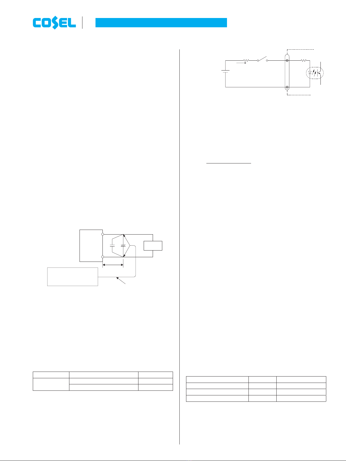
1.2 Inrush Current Limiting
¡An inrush current limiting circuit is built-in.
¡If you need to use a switch on the input side, please select one
that can withstand an input inrush current.
¿ KHEA30F/60F/90F/120F,
KHNA30F/60F/90F/120F
¡Thermistor is used in the inrush current limiting circuit. When you
turn the power ON/OFF repeatedly within a short period of time,
please have enough intervals so that a power supply cools down
before being turned on.
¿
KHEA240F/480F, KHNA240F/480F
¡Thyristor technique (KHEA/KHNA240F) and power relay tech-
nique (KHEA/KHNA480F) is used in the inrush current limiting
circuit.
1 Functions ¡When you turn the power ON/OFF repeatedly within a short period
of time, please have enough intervals so that the inrush current
limiting circuit becomes operative.
¡When the switch of the input is turned on, the primary inrush cur-
rent and secondary inrush current will be generated.
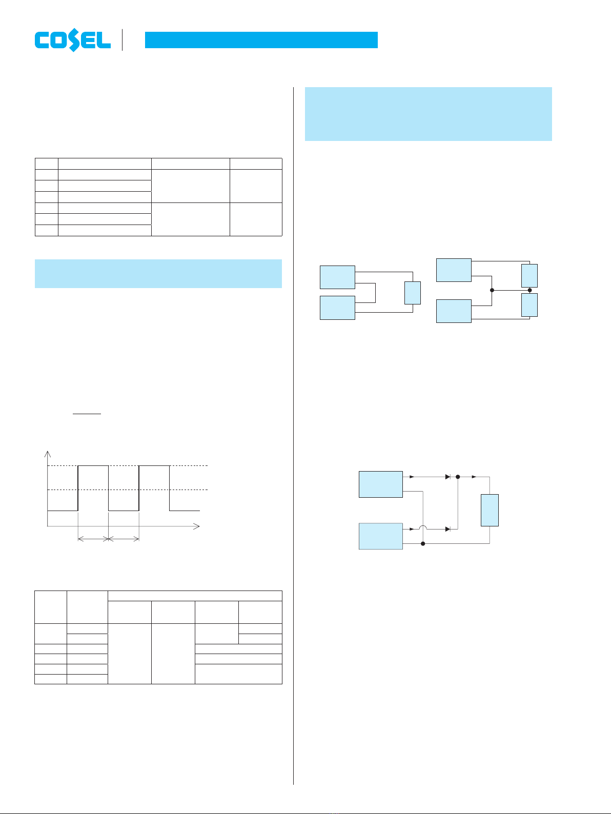
1.3 Overcurrent Protection
¿ KHEA30F/60F/90F, KHNA30F/60F/90F
¡A overcurrent protection circuit is built-in and activated over 105%
of the rated current. A unit automatically recovers when a fault
condition is removed. Please do not use a unit in short circuit and/
or under an overcurrent condition.
¡Hiccup Operation Mode (except KHEA/KHNA90F)
When the overcurrent protection circuit is activated and the output
voltage drops to a certain extent, the output becomes hiccup so
that the average current will also decrease.
¡Output Voltage Shutdown
If the output voltage drops according to the overcurrent protection
circuit operating continuously for about 0.5 second, the output
voltage may shut down. To recover the output voltage, remove a
condition that is causing an overcurrent, shut down the input volt-
age, wait more than 3 minutes and turn on the AC input again.
¿
KHEA120F/240F/480F, KHNA120F/240F/480F
¡An overcurrent protection circuit is built-in and activated over
101% of the peak current. A unit automatically recovers when a
fault condition is removed. Please do not use a unit in short cir-
cuit and/or under an overcurrent condition.
¡Hiccup Operation Mode
When the overcurrent protection circuit is activated and the out-
putvoltage drops to a certain extent, the output becomes hiccup
so that the average current will also decrease.
1.4 Peakcurrent Protection
¿
KHEA120F/240F/480F, KHNA120F/240F/480F
¡Peakcurrent protection is built-in (refer to Instruction Manual 3 for
Peak loading).
If this function comes into effect, the output is shut down.
A few seconds later, A unit automatically recovers.
But if the overcurrent condition has not been released, the output
will stop again (hiccup Operation Mode).
*The recovery time varies depending on input voltage and load
condition.
1.5 Overvoltage Protection
¿ KHEA30F/60F/90F, KHNA30F/60F/90F
¡An overvoltage protection circuit is built-in. If the overvoltage pro-
tection circuit is activated, shut down the input voltage, wait more
than 3 minutes and turn on the AC input again to recover the out-
put voltage. Recovery time varies depending on such factors as
input voltage value at the time of the operation.
¿
KHEA120F/240F/480F, KHNA120F/240F/480F
¡An overvoltage protection circuit is built-in.
AC-DC Power Supplies DIN Rail Type Instruction Manual
KH-22 June 29, 2020