Thales payShield 10K PS10-F User manual
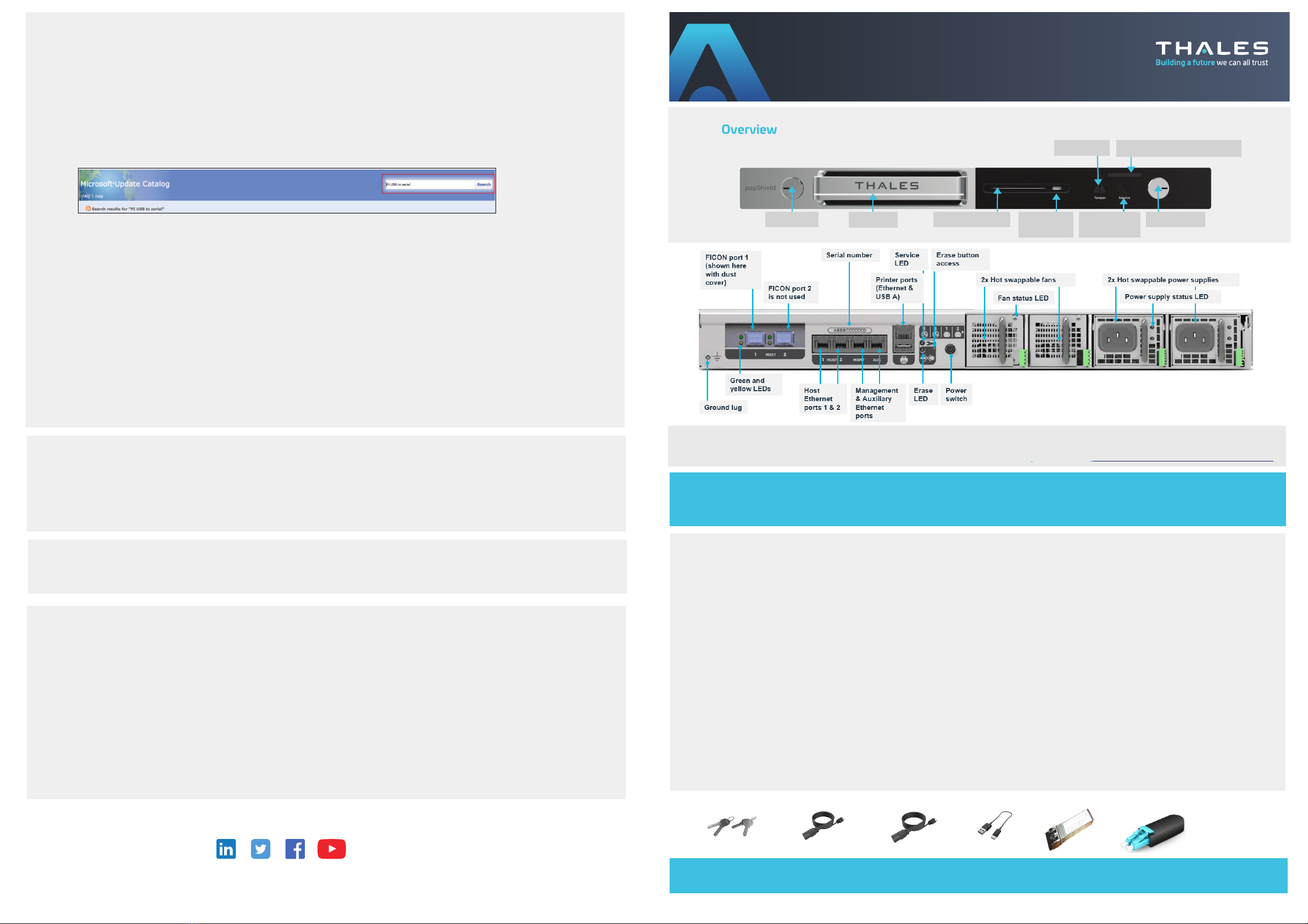
Device Overview
12. Configure payShield Manager
•Follow the instructions provided in the payShield Manager Quick start guide to complete the configuration of payShield Manager
13.Configuring the host ports
Depending upon the configuration connection required between the Host and the payShield 10K, you may require additional
information from your Network or Systems Support Group in order to complete this step.
•Using either the console or payShield Manager, configure the Host ports to suit your system requirements. The parameters you
need to enter will vary, depending upon the type of communications to be used.
Test the connection:
•The FICON board and transceivers can be tested using the FICNTEST console command. payShield Manager users can run this
from the payShield Manager virtual console. Note, that to run FICONTEST, you will need the loopback device provided with your
transceiver.
10. Connect using the console
The console terminal is pre-configured to communicate with the HSM via the USB-C to USB-A cable.
•Use the supplied USB-C to USB-A cable to connect the USB-C port on the front of the payShield 10K to your laptop
NOTE: If your laptop has a USB-C port, instead of a USB-A port, you will need to order or provide a standard USB-C to
USB-C cable.
•For Windows, ensure that all Windows updates have been applied and the laptop is connected to the internet before
connecting to the payShield. Upon connection, Windows will detect the new hardware and install the driver. The device
will appear as a new COM port.
•If the laptop cannot be connected to the internet, the drivers are available for download and manual installation from
the Microsoft Update Catalog: www.catalog.update.microsoft.com/Search.aspx?q=PI%20USB%20to%20serial
•Download the CAB file for the laptop operating system and extract the files into a folder
•Expand the "Other devices" section of the Device Manager and look for "Gadget Serial v2.4". Right click on that and select
the option to install the driver. Choose the option to browse for the driver and select the folder from the previous step.
•You may need to be signed in with an administrator account to install drivers
•Using a standard terminal emulation program, select the set-up for serial terminal emulation and configure it as follows:
•Baud Rate: 9600 bps
•Word Length: 8 bits
•Parity: None
•Stop Bits: 1 bit
Test the connection:
•Press the <Return> key on the console/laptop keyboard
The HSM should respond by displaying “Online>”, “Offline>”, or “Secure>” based on the position of the keys.
The appearance of this prompt indicates that the correct communications between the console and the HSM have been
established, but that no command has been entered.
Left key lock
Tamper light Service light with serial number
Health LED Smart card reader Right key lock
USB-C
console port
Service light
on/off button
Ethernet
ports 1 & 2
Service LEDSerial number 2x Hot swappable fans
Erase Button
access
Printer ports
(Ethernet & USB-A)
Management
& Auxiliary
Erase
LED
Power
switch
2x Hot swappable power supplies
Power supply status LED
Fan status LED
© Thales Group - 2018-2021• 007-000856-001 Rev A
payShield 10K PS10-F
Installation Quick start guide
007-000856-001
>cpl.thalesgroup.com <
Contact us – For all office locations and contact information, please visit cpl.thalesgroup.com/contact-us
User Documentation
The payShield 10K user manuals are available for download from the Thales CPL support website: https://supportportal.thalesgroup.com/csm
NOTE: The HSM FICON interface supports speeds up to 32Gbp/s, with the option of 8Gbp/s or 16Gbp/s, if available. If using a
switched fabric, the connection switch must have the connecting port type set to fabric port.
11.Connect cables for payShield Manager
•payShield Manager provides a secure GUI interface with an authenticated, encrypted connection allowing a full remote
or local management of the payShield 10K
•Remote payShield Manager requires an Ethernet cable from the Management Port into your network
•If you are not using DHCP, then you may need to use the console to set up the static IP address for payShield Manager.
(Refer to the payShield Manager Quick start guide. For the Console, refer to the payShield 10K Console Guide.)
Remove from packaging:
•Remove the Accessories box
•Remove the payShield 10K from the packaging, checking that the tamper evident bag containing the unit is not tampered
•Check that the serial number on the tamper evident bag matches that supplied by email or shipment confirmation by Thales
Remove the accessories from the Accessories box.
Verify the shipment's contents:
•payShield 10K PS10-F Host Security Module
•HSM Rail Kit
•2 AC power cables
•4 Security keys in tamper evident bags (2 copies -- 4 total keys)
•USB-C to USB-A cable (for console connectivity)
Carry out the following checks:
•Check that the tamper evident bag containing the keys is not tampered and the serial number matches that supplied by email or
shipment confirmation by Thales
•Locate the serial number on the key tag and verify that it matches the serial number on the unit
1. Assure Safety
•Before installing, and using this product, please read the Warnings and Cautions in the following document: payShield 10K Regulatory User
Warnings & Cautions
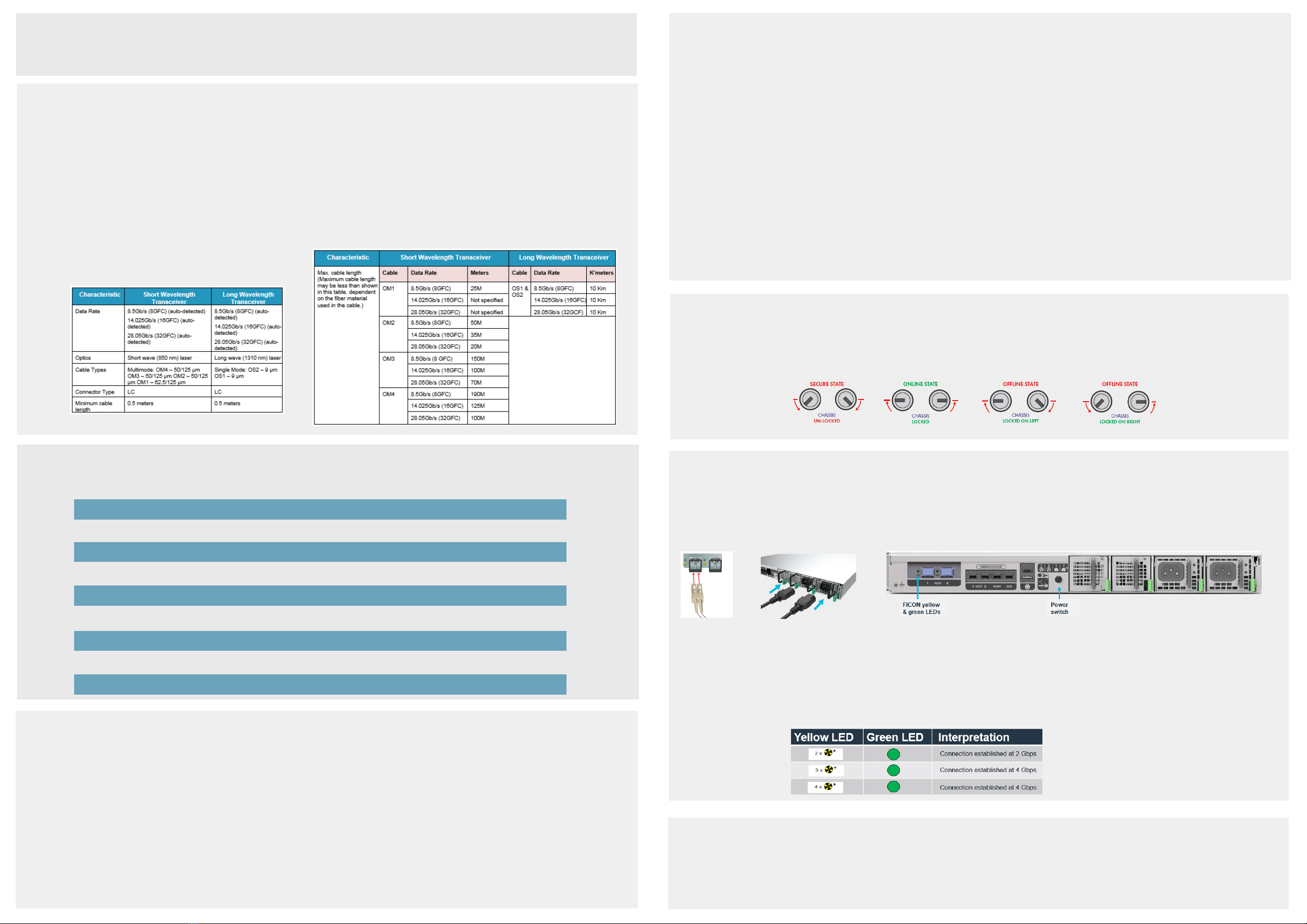
•Either a FICON Short Wave Small form-factor pluggable
transceiver (SFP) or FICON Long Wave SFP (ordered
separately)
•Loopback device
•payShield 10K Regulatory User Warnings & Cautions
document
•payShield 10K PS 10-F Installation Quick start guide (this
document)
•payShield Manager Quick start guide
2.Unpack
•The way in which you do this will vary, depending upon your system configuration; for example: Ethernet environment – issue a
PING command (both from the payShield 10K to the Host, and from the Host to the payShield 10K)
7.Lock the unit into the rack
The payShield 10K is physically locked into the rack via the two key locks located on the front of the unit.
NOTE: Each lock has its own key and each key is owned by a security officer.
To physically lock the unit into the rack, each key holder inserts their key into their respective lock and turns the lock to the locked position.
8.. Connect the Fiber optic cable, power cable and then turn the unit on
NOTE: When power is applied to the unit, there is a period of time before the unit is operational and either the console
or payShield Manager is available.
9.Configuring the payShield 10K
The payShield 10K can be configured via payShield Manager or via the console terminal.
NOTE: For payShield Manager and Host operation, the payShield must be ONLINE, i.e., the front panel keys are in the locked position.
•USB to 25 pin parallel printer cable
•payShield Manager smart cards
•payShield Manager Starter Kit
•payShield Manager Reader
•Confirm that you are using the appropriate Fiber optic cable and connector type, as defined in the tables in Step 4
•Plug the cable connectors into the LC connectors of Port 1
•Connect the power supplies
•Push the on/off power switch located on the back of the unit; the unit has power when the power switch is pressed in
To ensure that temperature ranges are not exceeded, consider airflow and temperature when installing the HSM in the rack. Once
installed, ventilation holes must not become obstructed, as that would reduce the air flow through the unit.
3.Insert the SFP
•Remove the dust cover from Port 1. Port 2 is not used.
•Install the SFP by sliding it into the housing. When the latch engages,
it clicks.
NOTE: Handling the SFP is a delicate operation -
take care not to damage the transceivers. Observe
standard Electrostatic Discharge (ESD) precautions
for handling electronic components.
•FICON interface cable - see tables below
For payShield Manager:
•A standard Ethernet cable for the Management Port
•A standard desktop PC or laptop with a web browser supported
by payShield Manager, (e.g. Chrome or Firefox)
For the console terminal:
•Wait for the health LED to turn solid white or solid red before proceeding
•Once the payShield is powered up, the FICON interface performs a Power On Self-test. The yellow LED indicates port activity while
the green LED indicates firmware operation. Refer to the payShield 10K Installation and User Guide for information regarding
additional LED indications
•For additional instruction, refer to the payShield Manager Quick start guide, the payShield 10K Installation and
User Guide, and the payShield 10K Console Guide
NOTE: Based on your order, additional items may be
included in your shipment. In certain circumstances,
the security keys and smart cards may be delivered
under separate cover to the two designated keyholders.
Optional accessories:
Operating temperature
Storage temperature
Transportation temperature
Operating humidity
Transportation humidity
Altitude
Overall rack dimensions (WxDxH)
Maximum Operating Power Consumption
1U rack 19” x 29” x 1.75” (482.6mm x 736.6 mm x 44.5mm)
80W
Storage humidity
4.Gather additional equipment
For printer ports:
Unpack the Thales box containing the Thales Universal Rack Mount Kit. The Mount Kit contains 2 rails and 10 M4 x 6 mm screws.
Remove inner rail from rack mount assembly.
•Position the inner rail on the side of the product with the safety catch toward the rear
•Align the rear hole of the rail with the rear hole on the chassis and attach using the M4 x 6mm screws provided
•Align the other 4 holes with the counter sink in the rail with the corresponding holes in the chassis, insert the M4 x 6mm screws, and tighten all the screws
•Repeat this to attach the second inner rail to the other side of the chassis
NOTE: The 1U 1000 mm Universal Rack Mount Kit is pre-assembled for use with square hole and unthreaded round hole racks.
This rack kit is suitable for racks and cabinets where the depth between front and rear posts is in the range 685.8mm – 939.8mm.
5.Determine your location
•Printer Interface cable (Optional) - Printer communication is via
USB peripheral cable for payShield Manager
For FICON ports:
•A standard desktop PC or laptop using terminal emulation software
Adjust rail length. (The rails support a range of rack mounting depths.)
Loosen the two rear retaining plate screws to enable the rear bracket to be extended.
Install outer rails into the rack.
•With both the left and right bearing retainers moved the entire way forward, align the inner rails mounted on the product with
the outer rails mounted in the rack
•You may need to apply gentle pressure to the ends of the inner rails to align them with the outer rails
•Slide the product into the rack until the safety latches engage
Push the safety catches in on both sides and slide the product fully into the rack. When sliding the unit into the rack for the first time, the last
few inches of travel may experience some resistance as the bearing retainers meet their backstops. The resistance can be overcome by applying
slightly more force to the front of the unit to achieve full insertion into the rack.
-100m to 2000m AMSL (Above Mean Sea Level)
5 – 93% (Relative non-condensing at 40°C)
5 – 93% (Relative non-condensing at 30°C)
-5°C to 45°C
-25°C to 70°C
5 – 85% (Relative non-condensing at 30°C)
0°– 40°C
6.Mount the rack
•Slide the inner rail until the safety catch locks
•Depress the safety catch and continue sliding to separate the inner and outer rails
Attach inner rail to the chassis.
•Align the bracket marked “FRONT” with the holes in the front post
•Once aligned, push the bracket forward until the snap mechanism engages
•Slide the rear bracket towards the rear post of the rack
•Align the bracket with the holes in the rear post at the same vertical position used for the front and snap it in
•Tighten the two rear retaining screws
IMPORTANT: Slide the bearing retainer all the way forward to avoid damaging the rail kit when the product is installed.
Insert product into the outer rails.
Other Thales Network Hardware manuals

Thales
Thales SafeNet KeySecure k470 User manual

Thales
Thales VesseLINK Certus 350 User manual

Thales
Thales Cryptel-IP CE 621 User manual

Thales
Thales Z-Max.Net User manual

Thales
Thales ProtectToolkit 5.9.1 Operator's manual

Thales
Thales CipherTrust Manager k160 User manual

Thales
Thales CipherTrust Manager k160 User manual

Thales
Thales Cinterion DGL61-W User manual

Thales
Thales payShield 10K PS10-D User manual


