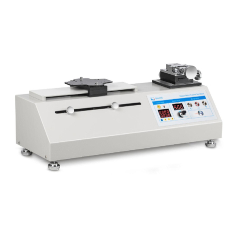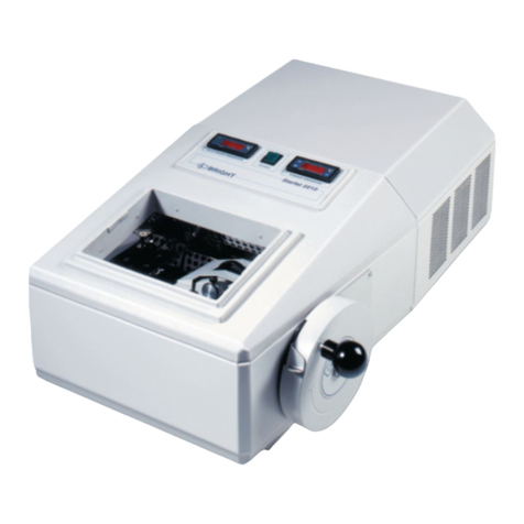
8600 Series
___________________________
Table
of
Contents
Table
of
Contents
Section 1 - Installation
and
Start-up
...............
1 - 1 Section 5-Maintenance
.........................
5 - 1
1.1
Freezer Components
.........................
1 - 1
5.1
Cleaning the Cabinet Exterior
.................
.5
- 1
1.2
Control Panel Keys, Displays and Indicators
......
1 - 2 5.2 Cleaning the Air Filter
.......................
.5
- 1
1.3
Operation
of
the Keypad
......................
1- 3 5.3 Cleaning the Condenser
.......................
5 - 1
1.4 Displays
..................................
1- 3
a.
Cleaning the Water-cooled Condenser
.........
.5
1
1.5
Installing the Freezer
.........................
1- 3 5.4 Defrosting the Chamber
......................
.5
- 1
a.
Choosing the Location
.....................
1 - 4 5.5 Cleaning the Door Gasket
....................
.5
- 2
b. Installing the Wall Bumpers
.................
1 - 4 5.6 Vacuum Relief Port
..........................
.5
- 2
c. Installing the Shelves
......................
1- 4 5.7 Replacing the Battery(s)
.....................
.5
-3
d. RS-232 Communications
....................
1- 4 5.8 Preparing the Unit for Storage
..................
5 - 3
e. Remote Alarm Contacts and Analog Output
.....
1- 5 Preventive Maintenance
.........................
.5
- 4
f.
Attaching the Power Cord
...................
1- 5
g. Connecting the Unit to Electrical Power
........
1 - 5 Section 6 • Factory
Options
......................
6 - 1
1.6 Freezer Start-Up
.............................
1 - 5
6.1
BUS (Back Up System)
.......................
6 - 1
a.
Setting the Operating Temperature
............
1 - 5
a.
Installing the vent stack, solenoid and injection
b. Setting the High Temperature Alarm
...........
1 - 6 assembly
................................
6 - 1
c.
Setting the Low Temperature Alarm
...........
1 - 6
b.
Installing the Temperature Probe
..............
6 - 2
e.
Access Code . . . . . . . . . . . . . . . . . . . . . . . . . . .
...
1- 6
c.
Connecting the probe/solenoid hamess
.........
6 - 2
1.7
Run Mode
..................................
1- 6
d.
BUS Control Panel
........................
6 - 3
Chart
1-1
......................................
1- 7
e.
Setting the Optional BUS Set Point
............
6 - 3
f.
Cleaning the Vent Stack
.....................
6 - 3
Section 2 •
Calibrate
...........................
.2 -1
g.
Disconnecting the fitting assembly and
2.1
Calibrate Mode
.............................
.2 -1 transfer hose
.............................
6 - 3
a.
Calibrating the Control Probe
................
2 - 1 6.2 Chart Recorder
..............................
6 - 4
b.
Calibrating The Optional Sample Probe
.......
.2 -1
a.
Installing the chart paper
...................
6 - 4
Chart
2-1
......................................
2 - 2
c.
Recorder Calibration
.......................
6 - 4
6.3 Datalogger
.................................
6 - 5
Section 3 - Configuration
.......................
.3
-1 6.4 Water-Cooled condenser
.......................
6 - 5
3.1
Configuration Mode
..........................
3 - 1 6.5 Five Inner Door Option
.......................
6 - 5
a.
High Alarm Test
..........................
3 - 1
b.
Low Alarm Test
..........................
3 - 1 Section 7 • Specifications
.........................
7-1
c.
System Battery Test
.......................
3 - 1
d. BUS Battery Test
........................
.3
- 1 Section 8 - Spare
Parts
..........................
8 - 1
e.
Display Temperature
......................
.3
-1
f. Clear High Stage Alarm
....................
.3 -1 Section 9 - Refrigeration Schematics
..............
9 - 1
g.
Setting an Access Code
....................
.3 - 2
h.
RS-485 Address
.........................
.3
- 2 Section 10 -Electrical Schematics
..............
.10 - 1
i.
Back Up System Type
......................
3 - 2 Section
11
-
Warranty
.........................
11
- 1
Section 4 -
Alarms
...
..........................
.4 -1 AppendixA - Handling
Liquid
Nitrogen
............
A - 1
4.1
Alarms
...................................
.4 -1
a.
Wrong Power Alarm
.......................
.4 -1 Appendix B • Handling
Liquid
C02
...............
B - 1
b.
High Stage System Failure Alarm
............
.4 -1
c. Voltage Compensation Alarm
.................
4 - 1
First
Aid
......................................
C - 1
d.
Multiple Alarms
..........................
.4 -1
4.2 Probe Failure Alarms
........................
.4 - 2
iv


