© 2011 Thorlabs
Table of Contents
Foreword 4
Part I General Information 5
................................................................................................................................... 51 Safety
Part II Getting Started 6
................................................................................................................................... 61 Ordering Codes and Accessories
................................................................................................................................... 62 Unpacking
................................................................................................................................... 63 Preparation
................................................................................................................................... 84 Operating Elements
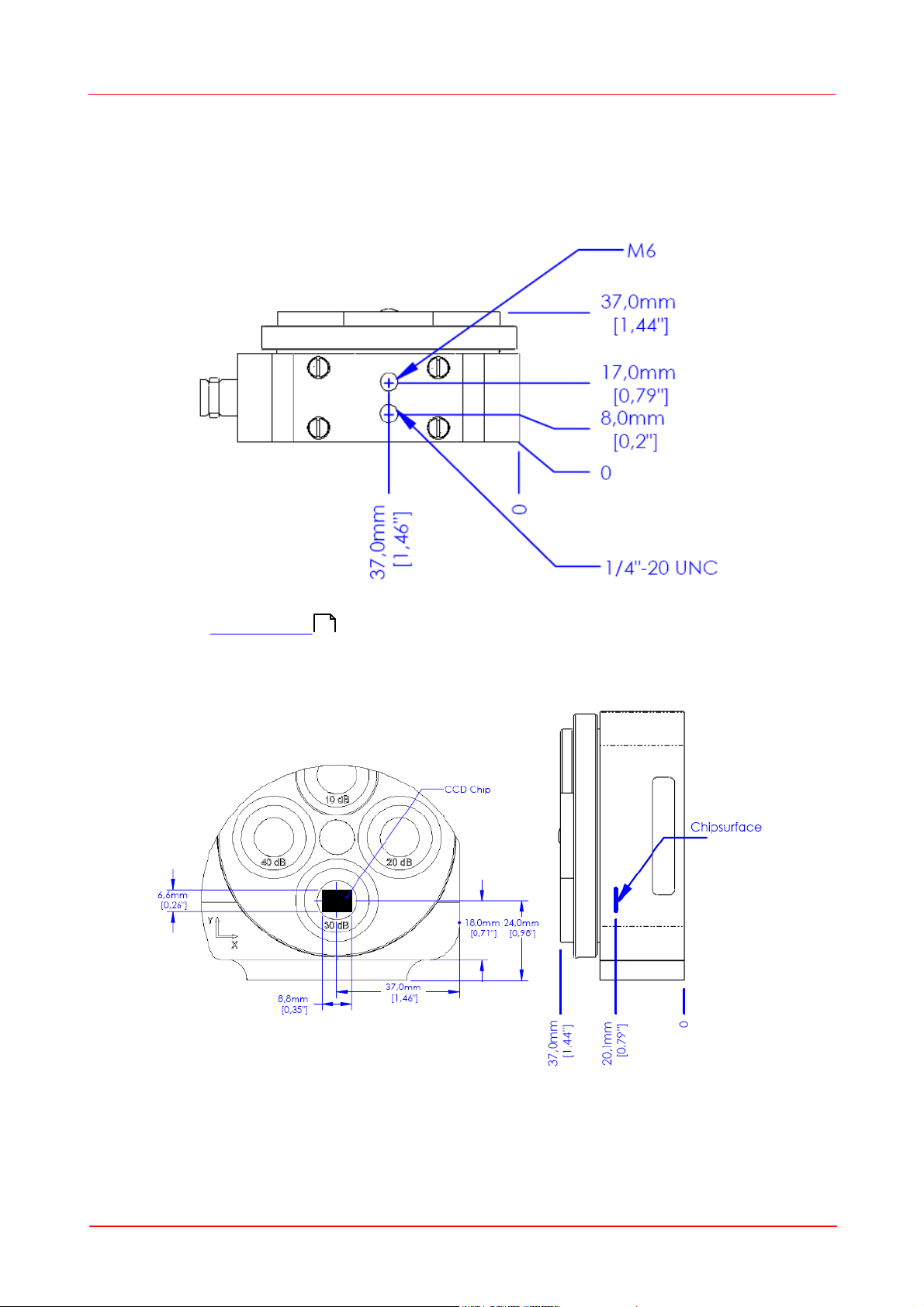
......................................................................................................................................................... 8Mounting and Sensor Position
......................................................................................................................................................... 9Filter Wheel
......................................................................................................................................................... 11Connectors
......................................................................................................................................................... 12Trigger Input
Part III Operating the Beam Profiler 13
................................................................................................................................... 131 Requirements
................................................................................................................................... 132 Installation
......................................................................................................................................................... 13Softw are Installation
......................................................................................................................................................... 23Connection to the PC
......................................................................................................................................................... 24Start the Application
................................................................................................................................... 263 The Graphics User Interface (GUI)
......................................................................................................................................................... 26GUI Overview
......................................................................................................................................................... 31Child Window s
.................................................................................................................................................. 332D Projection
.................................................................................................................................................. 363D Profile
.................................................................................................................................................. 37X,Y Profiles
.................................................................................................................................................. 39Calculation Results
........................................................................................................................................... 40Pass/Fail Test
.................................................................................................................................................. 41Plots
........................................................................................................................................... 42Plot Positions
........................................................................................................................................... 43Plot Pow er
........................................................................................................................................... 44Plot Gaussian Fit
........................................................................................................................................... 45Plot Orientation
........................................................................................................................................... 46Beam Stability
......................................................................................................................................................... 47Save Settings
................................................................................................................................... 484 Measurement with the Beam Profiler
......................................................................................................................................................... 49Operating the Instrument
......................................................................................................................................................... 50Device Settings
......................................................................................................................................................... 59Application Settings
......................................................................................................................................................... 65Pow er Correction
......................................................................................................................................................... 66Ambient Light Correction
......................................................................................................................................................... 67Hot Pixel Correction
......................................................................................................................................................... 69Measurement Results
......................................................................................................................................................... 70Save Measurement Results
......................................................................................................................................................... 75Pow er Ranges
......................................................................................................................................................... 76Pulsed Laser Sources
.................................................................................................................................................. 76No Trigger
.................................................................................................................................................. 76Softw are Trigger