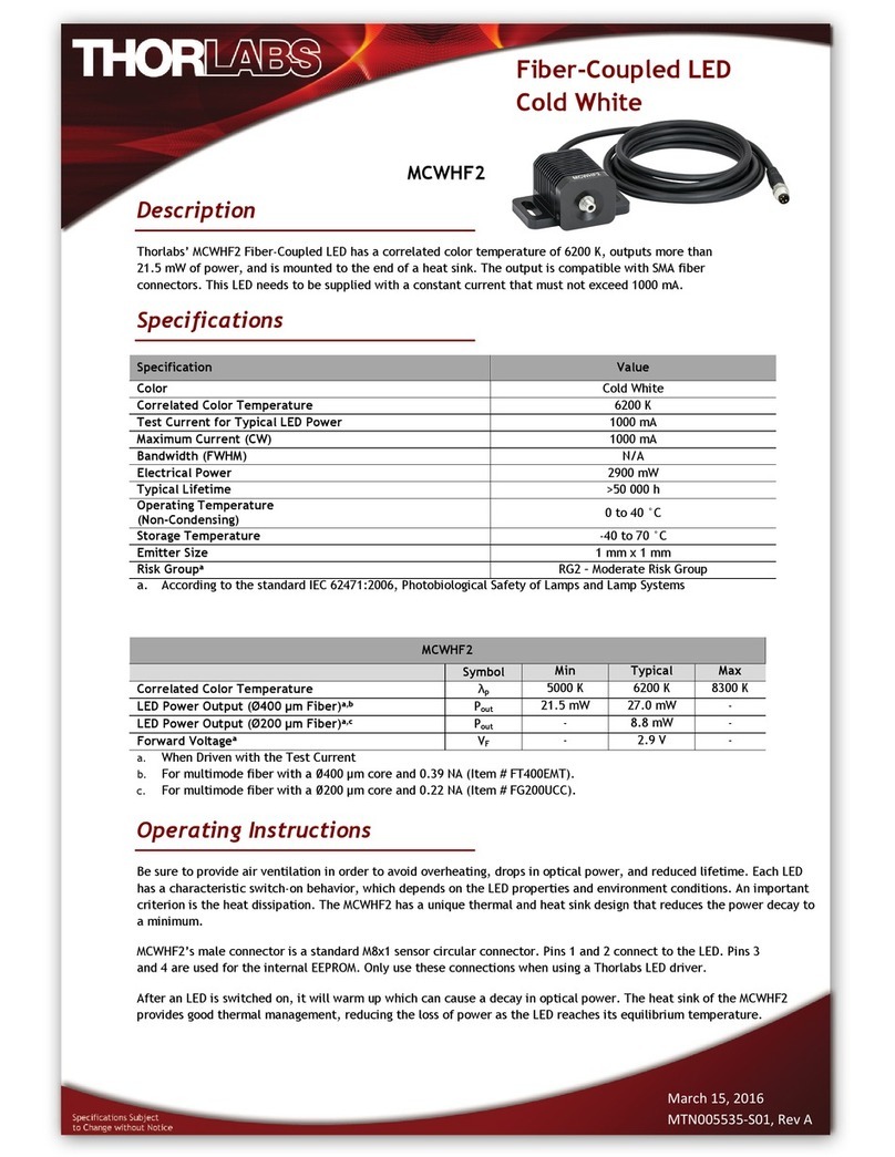
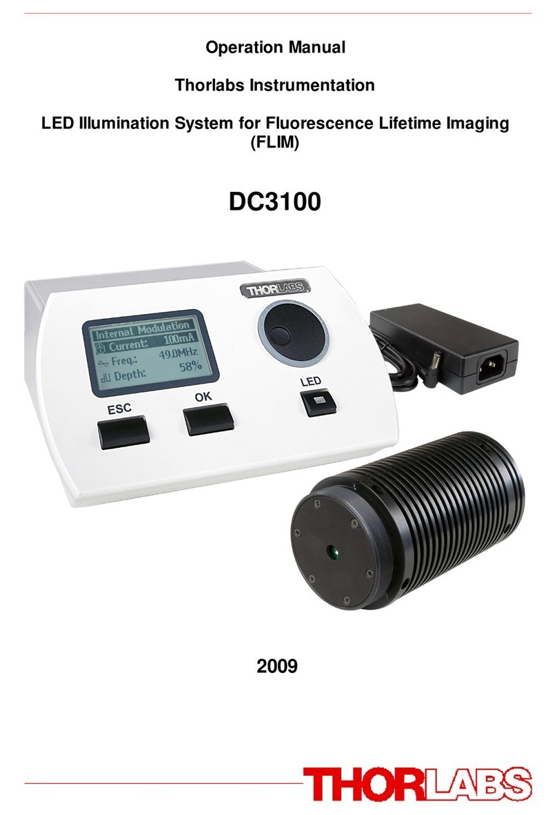
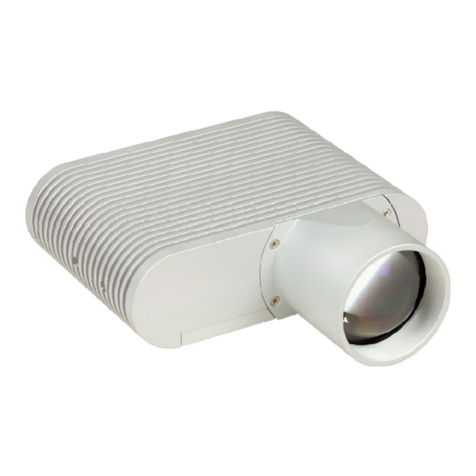
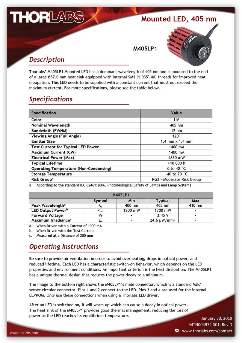
THORLABS LEDD3 Series User manual

2009
Operation Manual
Thorlabs Instrumentation
LED Illumination System for Fluorescence Lifetime Imaging
(FLIM)
LEDD3

Version:
Date: 1.2
03.03.2009
© 2009Thorlabs
© 2009 Thorlabs

© 2009 Thorlabs
Table of Contents
Foreword 3
Part I General Information 5
................................................................................................................................... 51Safety
................................................................................................................................... 82 Ordering Codes and Accessories
Part II Getting Started 10
................................................................................................................................... 101Unpacking
................................................................................................................................... 102Preparation
................................................................................................................................... 113Physical Overview
.........................................................................................................................................................11Operating Elements on the Front Panel
.........................................................................................................................................................12Operating Elements on the Rear Panel
.........................................................................................................................................................12Operating Elements on the LED Head
Part III Operating the LEDD3 14
................................................................................................................................... 141Operation and Settings
.........................................................................................................................................................14Navigating the Menus
.........................................................................................................................................................15Operation Modes
.........................................................................................................................................................18Settings and Configuration
................................................................................................................................... 202Remote Application
.........................................................................................................................................................20Installation
.........................................................................................................................................................28Operating the LEDD3 by the Remote Application
................................................................................................................................... 323Changing the LED
Part IV Computer Interface 34
................................................................................................................................... 341Connecting a Computer
................................................................................................................................... 342LEDD3 Utility Software
................................................................................................................................... 353Command Reference
.........................................................................................................................................................35Command List
.........................................................................................................................................................35Description
................................................................................................................................... 394 Status Reporting
Part V Maintenance and Repair 41
................................................................................................................................... 411Maintenance
................................................................................................................................... 412Firmware Update
................................................................................................................................... 413 Troubleshooting
Part VI Appendix 44
................................................................................................................................... 441Warranty
................................................................................................................................... 452Certifications and Compliances
................................................................................................................................... 473Technical Data
.........................................................................................................................................................47Common Data
.........................................................................................................................................................47Technical Data
.........................................................................................................................................................48LED for Frequency Domain FLIM
................................................................................................................................... 524Thorlabs 'End of Life' Policy (WEEE)
.........................................................................................................................................................52Waste Treatment on your own Responsibility
© 2009 Thorlabs
.........................................................................................................................................................52Ecological Background
Part VII Listings 54
................................................................................................................................... 541List of Acronyms
................................................................................................................................... 542List of Figures
................................................................................................................................... 563Addresses
Part VIII Application Note 58
................................................................................................................................... 581Fluorescence Lifetime Imaging (FLIM)
.........................................................................................................................................................58Time Domain FLIM
.........................................................................................................................................................59Frequency Domain FLIM
Index 1

We aim to develop and produce the best solution for your application
in the field of optical measurement technique. To help us to come up
to your expectations and develop our products permanently we need
your ideas and suggestions. Therefore, please let us know about
possible criticism or ideas. We and our international partners are
looking forward to hearing from you.
Thorlabs GmbH
Thispartoftheinstructionmanualcontainseveryspecificinformationonhow
to handle and use the LEDD3 - FLIM LED Driver. A general description is
followedbyexplanationsofhowtooperatetheunitremotelyviatheUSB
connection.
Attention
This manual contains "WARNINGS" and "ATTENTION" label in
this form, to indicate danger for persons or possible damage of
equipment.
Please read these advises carefully!
NOTE
Thismanualalsocontains"NOTES"and"HINTS"writteninthisform.
© 2009 Thorlabs

General Information
LEDD3 - FLIM LED Driver User
Manual
Part I

5General Information
© 2009 Thorlabs
1General Information
TheLEDmodulatingsystem(LEDD3series)isdesignedforfrequencydomain
FluorescenceLifetimeImaging(FLIM)andothermicroscopyapplicationsthat
requiremodulatedhigh-powerLEDilluminationsources.
Thecompact LED driver in theLEDD3 series can supply ahigh current (up to 1A)to
high-powerLEDs.TheLEDD3seriessystemincludesanopticalhead,modulating
electronics,andaheat sink designedtodissipatetheheatgeneratedby high-power
LEDs.Thedesignoftheheadallowstheusertomountanycompatiblestar-shaped
PCB packaged LED.
Pleaserefer tochapter FluorescenceLifetimeImagingforapplicationnotes.
1.1 Safety
GAttentionG
All statements regarding safety of operation and technical data in
this instruction manual will only apply when the unit is operated
correctly.
Before applying power to your LEDD3 system, make sure that the
protective conductor of the 3 conductor mains power cord is
correctly connected to the protective earth contact of the socket
outlet!
Improper grounding can cause electric shock with damages to
your health or even death!
The LEDD3 must not be operated in explosion endangered
environments!
The LED head, control inputs and outputs must only be
connected with duly shielded connection cables.
Only with written consent from Thorlabs may changes to single
components be carried out or components not supplied by
Thorlabs be used.
Do not obstruct the air ventilation slots in housing!
Do not remove covers!
Refer servicing to qualified personal!
This precision device is only dispatchable if duly packed into the
complete original packaging including the plastic form parts. If
necessary, ask for a replacement package.
Mobile telephones, cellular phones or other radio transmitters are
not to be used within the range of three meters of this unit since

6LEDD3 - FLIM LED Driver User Manual
© 2009 Thorlabs
the electromagnetic field intensity may then exceed the maximum
allowed disturbance values according to IEC 61326-1.
This product has been tested and found to comply with the limits
according to IEC 61326-1 for using connection cables shorter than
3 meters(9.8feet).
GCautionG
The head of LEDD3 can contain an UV light LED! In this case the
LED radiates intense UV light during operation. Precautions must
be taken to prevent looking directly at the UV light with
unprotected eyes.
Do not look directly into the UV light or look through the optical
system during operation of the device. This can be harmful to the
eyes even for brief periods due to the high intensity of the UV light.
If there is the possibility to receive a reflection of the UV light, UV
light protective glasses have to be used to prevent that UV light
can catch one's eye directly.
If viewing the UV light is necessary, use UV light protective
glasses to avoid damage by the UV light.
GCautionG
The head of the LEDD3 is also a heat sink for the LED and will be
heated up to more than 50°C!

7General Information
© 2009 Thorlabs
GAttentionG
The following statement applies to the products covered in this
manual, unless otherwise specified herein. The statement for other
products will appear in the accompanying documentation.
Note: This equipment has been tested and found to comply with
the limits for a Class B digital device, pursuant to Part 15 of the
FCC Rules and meets all requirements of the Canadian
Interference-Causing Equipment Standard ICES-003 for digital
apparatus. These limits are designed to provide reasonable
protection against harmful interference in a residential installation.
This equipment generates, uses, and can radiate radio frequency
energy and, if not installed and used in accordance with the
instructions, may cause harmful interference to radio
communications. However, there is no guarantee that interference
will not occur in a particular installation. If this equipment does
cause harmful interference to radio or television reception, which
can be determined by turning the equipment off and on, the user is
encouraged to try to correct the interference by one or more of the
following measures:
·Reorient or relocate the receiving antenna.
·Increase the separation between the equipment and receiver.
·Connect the equipment into an outlet on a circuit different from
that to which the receiver is connected.
·Consult the dealer or an experienced radio/T.V. technician for
help.
Thorlabs GmbH is not responsible for any radio television
interference caused by modifications of this equipment or the
substitution or attachment of connecting cables and equipment
other than those specified by Thorlabs GmbH. The correction of
interference caused by such unauthorized modification,
substitution or attachment will be the responsibility of the user.
The use of shielded I/O cables is required when connecting this
equipment to any and all optional peripheral or host devices.
Failure to do so may violate FCC and ICES rules.

8LEDD3 - FLIM LED Driver User Manual
© 2009 Thorlabs
1.2 Ordering Codes and Accessories
Ordering code Short description
LEDD3-365 LEDD3 - FLIM LED Driver with LED Head @ 365nm
LEDD3-405 LEDD3 - FLIM LED Driver with LED Head @ 405nm
LEDD3-470 LEDD3 - FLIM LED Driver with LED Head @ 470nm
LEDD3-630 LEDD3 - FLIM LED Driver with LED Head @ 630nm
Other wavelength on request ranging from 365nm up to 940nm.
Pleasevisit ourhomepage http://www.thorlabs.comforfurtherinformation.

Getting Started
LEDD3 - FLIM LED Driver User
Manual
Part II

10 LEDD3 - FLIM LED Driver User Manual
© 2009 Thorlabs
2Getting Started
2.1 Unpacking
Inspectthepackagingfordamage.
Iftheshippingcontainerseemstobedamaged,keepit untilyouhaveinspectedthe
contentsandyouhaveinspectedtheLEDD3mechanicallyandelectrically.
Verifythatyouhavereceivedthefollowingitems:
1. 1 LEDD3 (main unit and LED head)
2. 1 Powercord,connectoraccordingtoorderingcountry
3. 1 Power supply 12V / 3.75A
4. 1 USB cable
5. 1 Operationmanual
6. 1 Applications and driver CD
2.2 Preparation
1.Connect LED head cable with socket labeled "LED" at the back of the main
controlunit,seefigure1
2.Connectpowersupplycablewithmaincontrolunit,useonlythepowersupply
suppliedwithyourLEDD3unit
3.Pluginpowersupply
Figure 1 Connecting the LED Head
GAttentionG
Prior to switching on your LEDD3 please check if the line voltage
corresponds to the input voltage range of the power supply!
Turntheunitonbypressingthepowerswitchontherearsideoftheunit.
Afterthedeviceispowered up, the graphics display willshowa'Welcome'screen

11Getting Started
© 2009 Thorlabs
fora fewseconds.
TheLEDD3isimmediatelyreadytouseafterturningon.Theratedaccuracyis
reached,however,afterawarming-upperiodofapproximately10minutes.
2.3 Physical Overview
2.3.1 Operating Elements on the Front Panel
Figure 2 Display and Operating Elements on the Front Panel

12 LEDD3 - FLIM LED Driver User Manual
© 2009 Thorlabs
2.3.2 Operating Elements on the Rear Panel
Figure 3 Operating Elements on the Rear Panel
2.3.3 Operating Elements on the LED Head
Figure 3a Operating Elements on the LED Head

Operating the LEDD3
LEDD3 - FLIM LED Driver User
Manual
Part III

14 LEDD3 - FLIM LED Driver User Manual
© 2009 Thorlabs
3Operating the LEDD3
TheLEDD3caneitherbecontrolledviathefrontpanelofthemainunit(seechapter
OperationandSettings) or by a remote application (see chapter Remote
Application).
3.1 Operation and Settings
Thefollowingsubchapterscontainthedescriptionabouttheoperationofthe
LEDD3.
3.1.1 Navigating the Menus
TheLEDD3iscontrolledbythreebuttonsandthemulti-controlknobonthefront
panel.ThetwobuttonsbelowthegraphicsdisplayhaveanEnterandEscape
functionality.ThebuttonwithLEDindicatorisusedtoswitchtheLEDonoroff.The
multi-controlisusedtoselectthedesiredmenuortochangethesettings.
Afterswitching on theLEDD3 a 'Welcome' screen appears for a few seconds.
Figure 4 Welcome Screen
Incase noLEDheadis connectedyouwillbe promptedtoswitchoff themainunit,
connecttheLEDheadandswitchonthedevice.
Thedisplaywill show the screen ofoneofthe 3 LED operation modes(Constant
Current, InternalModulation or External Control Mode).The'MainMenu'canbe
accessedviathe'ESC' button.
Figure 5 Main Menu
Toselectanoperationmodeoraconfigurationdisplaythemulti-controlknobis
used.Pressthe'Ok'buttontoentertheselecteditem.

15Operating the LEDD3
© 2009 Thorlabs
3.1.2 Operation Modes
Onlyifoneofthethreeoperationmodes(ConstantCurrent,InternalModulationor
ExternalControl)isselectedtheLEDcanbeenabled/switchedon.
Itispossibleto leave theactivemodewhentheLEDis switched on andenterthe
mainmenu.However,theLEDhastoswitchoffbeforeyoucanenteranother
operationmode.This canbedonewhilethe mainmenuisselectedby pressingthe
LEDbutton.
Constant Current Mode
The'ConstantCurrentMode'providesaconstantnon-modulatedLEDcurrent.The
currentcanbesetdirectlywiththemulti-controlknob.Noconfirmationisnecessary.
The'Ok'buttonhasnofunctionalitywithinthismode.TheLEDisswitchedonoroff
withtheLED button.TheLEDcurrent canbechangedwhenthe LEDisoffaswell as
whenitis in operation.Thisallowstoincreaseor reducethebrightnessoftheLED.
Thecurrentlimitisdisplayedatthebottomofthescreen.
Returntothemainmenuwiththe'ESC'button.
Figure 6 Constant Current Mode
Internal Modulation Mode
Thismode can be used toapply a sine wave modulationto the LED with adefined
frequency.
The'InternalModulationMode'featuresthreesettings:current,frequencyand
modulationdepth.Thefirstparameteristhe DCcomponent. Thefrequencycanbe
setbetween10MHzand100MHzinstepsof0.1MHz.Themodulationdepth
describestherelationbetweenconstantandvariablecomponent.
Figure 7 Internal Modulation Mode
Tochangethesettingsselectoneoftheparametersusingthemulti-controlknoband
pressthe'Ok'button.Thecorrespondingscreenappearsandthevalueforthe
current,thefrequencyorthemodulationdepthcanbeadjustedwiththemulti-control

16 LEDD3 - FLIM LED Driver User Manual
© 2009 Thorlabs
knob.Changingthevaluewilltakeeffectimmediately.However,sincetheediting
modeis activethevaluehas tobeconfirmedwith the'Ok'buttonor canbecanceled
withthe'ESC'button.
Figure 8 Internal Modulation - Current Adjustment
Figure 9 Internal Modulation - Frequency Adjustment
Figure 10 Internal Modulation - Modulation Depth Adjustment
Seethechapter TechnicalDataforinformationaboutcut-offfrequenciesforcertain
LEDs.
Thefollowingdiagramillustratesthedefinitionofcurrentandmodulationdepth:

17Operating the LEDD3
© 2009 Thorlabs
Figure 11 Definition of the Parameter Current and Modulation Depth
External Control Mode
ThismodeallowstocontroltheLEDD3byanexternalsignal.
The'ExternalControlMode'hasnoparametersettings.TheLEDcanonlybe
controlledvia theBNCconnectorattherearpaneloftheLEDD3.Theapplied
voltagecorresponds totheLEDcurrent.1VisequivalenttoaLEDcurrentof
100mA.Amaximum voltageof10Vcanbe applied,whichresultsina currentof
1000mA.
Pleasenote:Themaximumcurrentislimitedbytheuserdefinedcurrentlimitsetin
the'AdjustLimit'menu.
Figure 12 External Control Mode
TheModulationFrequencyrangeis0to100kHzandvalidforsinewavemodulation.
Thelastselectedoperation mode will be saved. Afterswitchingonthe LEDD3 again
thisoperationmodewillbeautomaticallytheactivemode.Allsettingsaresavedand
validatedafterashutoff.Thecurrentsettingsinthe'ConstantCurrentMode'andin

18 LEDD3 - FLIM LED Driver User Manual
© 2009 Thorlabs
the'InternalModulationMode'aretwoseparateparametersandwillbehandled
individually.
3.1.3 Settings and Configuration
Therearesettingsandsystemconfigurations,whichcanbeaccessedviathemain
menu.Toenterthemainmenufromoneofthe operationmodespressthe'ESC'
button.
Figure 13 Main Menu
Selectanitemwiththemulti-controlknobandpressthe'Ok'buttontoaccessthe
desiredsettingorconfigurationpanel.
User Limit
Thecurrentlimitcanbechangedbyselecting'UserLimit'.Thefollowingscreen
appearsandtheLEDcurrentlimitcanbesetusingthemulti-controlknob.Thenew
valuehastobeconfirmedwiththe'Ok'buttonorcanceledwiththe'ESC'button.The
LEDcurrentlimitcanbesetuptothemaximumLEDcurrentlimit(LEDImax),which
isdefinedin the EEPROM of theLEDhead.See next section for moreinformation.
Figure 14 LED Current Limit Setting
LED Configuration
IncaseanewLEDwasinstalledtheLEDsmaximumcurrentandfrequencyneedto
beconfigured.ThesevaluesaresavedintheEEPROMoftheLEDheadandcanbe
changedinthe'LEDConfiguration'menu.
Thismenuentryishiddeninnormaloperationmode.Gotothe'UserLimit'screen
describedaboveandholdthe"LED"button foraboutthreeseconds.
A submenuappearsandtheLEDsmaximumcurrent(LEDImax)andfrequency
(LEDfmax)canbeset.Pressthe'Ok'buttontoselectoneoftheselimits.Themulti-
controlknobisusedtochangethevalueandhastobeconfirmedwiththe'Ok'button
orcanceledwiththe'ESC'button.
This manual suits for next models
4
Table of contents
Other THORLABS Lighting Equipment manuals

THORLABS
THORLABS BC106-VIS User manual

THORLABS
THORLABS SLS401 User manual

THORLABS
THORLABS DC3100 Series User manual

THORLABS
THORLABS HPLS343 User manual

THORLABS
THORLABS MCWHF2 User manual

THORLABS
THORLABS SLS203L User manual

THORLABS
THORLABS PSY240E User manual

THORLABS
THORLABS SLS201L User manual

THORLABS
THORLABS LDM21 User manual

THORLABS
THORLABS SLS205 User manual