THORLABS SLS303 User manual

SLS303
Stabilized Benchtop IR
Light Source
User Guide

Stabilized Benchtop IR Light Source
Table of Contents
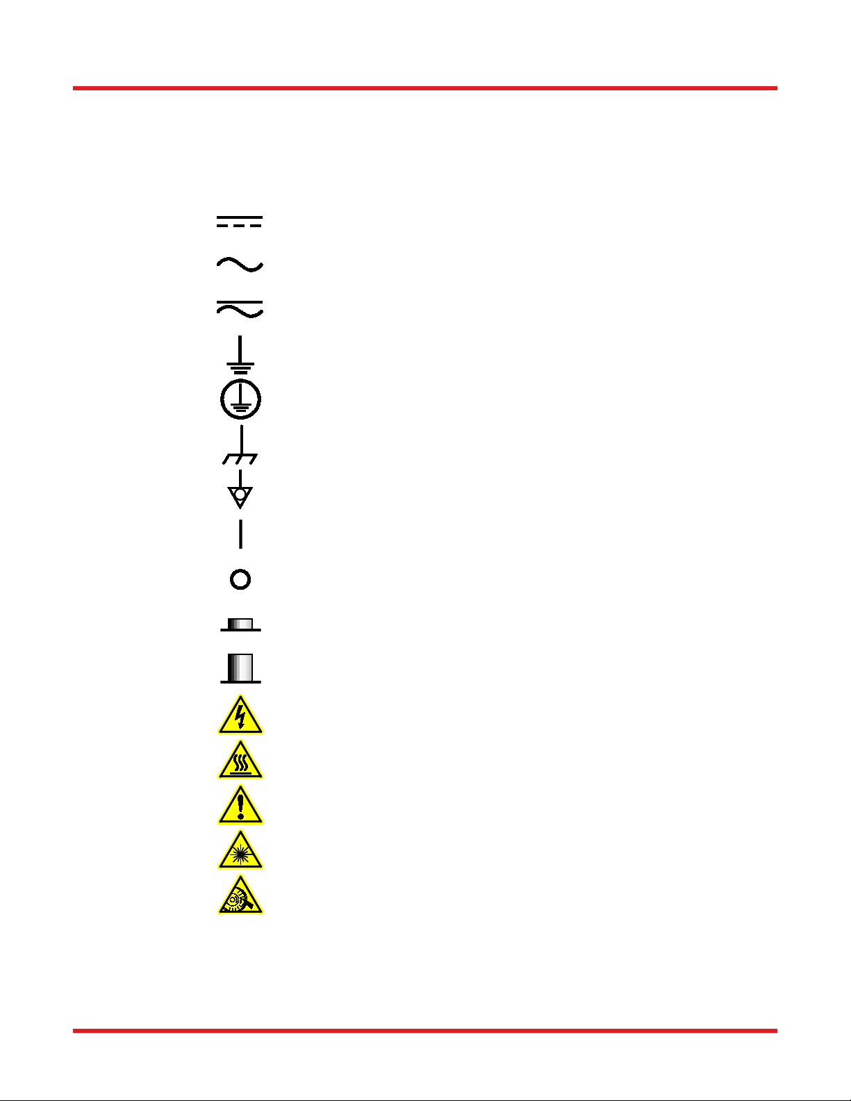
Chapter 1 Warning Symbol Definitions.............................................................................................1
Chapter 2 Safety...................................................................................................................................2
Chapter 3 Product Overview ..............................................................................................................3
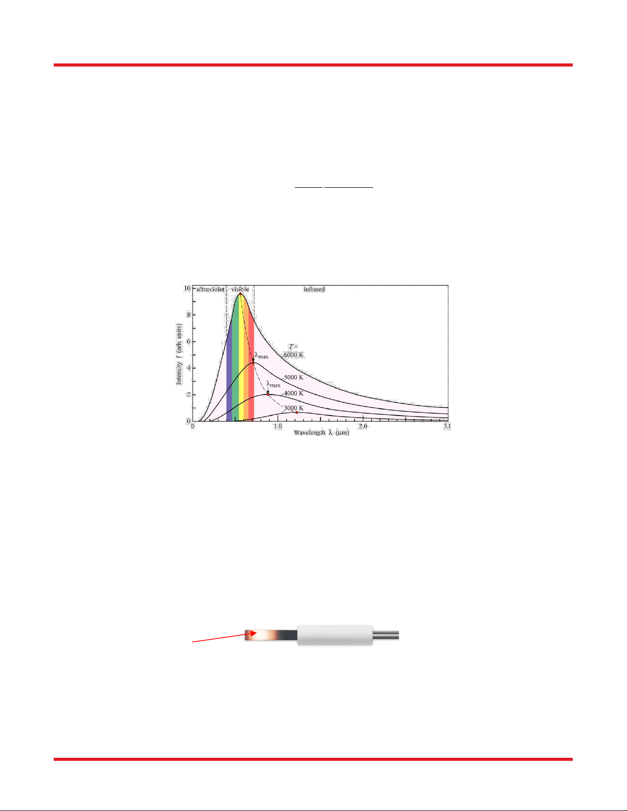
3.1. Planck's Law and Blackbody Radiation ...................................................................... 3
3.2. Silicon Nitride Globar ................................................................................................... 3
3.3. Optical Configuration ................................................................................................... 4
3.4. Output Stabilization...................................................................................................... 5
Chapter 4 Getting Started ...................................................................................................................6
4.1. Parts List ....................................................................................................................... 6
4.2. Unpacking ..................................................................................................................... 6
4.3. Operation Elements...................................................................................................... 7
4.3.1. Lamp Housing Front and Back Panels .................................................................................7
4.3.2. Controller Front Panel ...........................................................................................................7
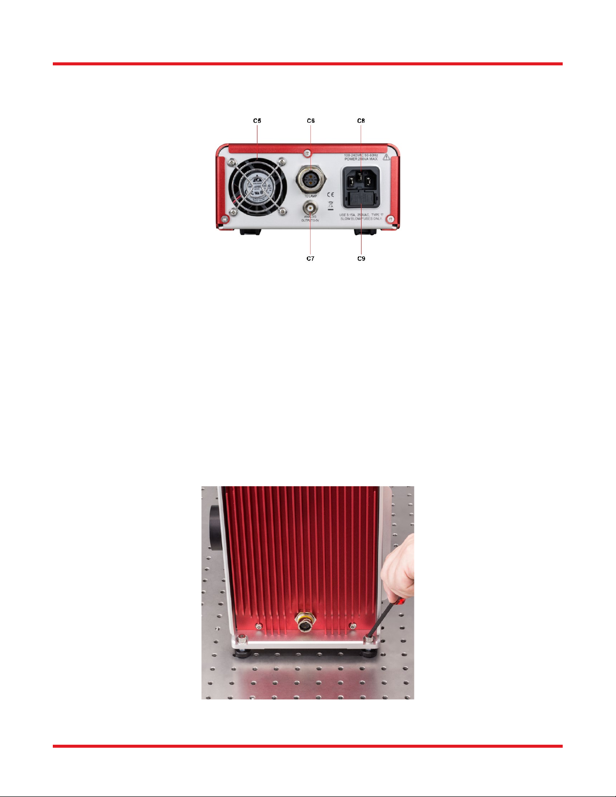
4.3.3. Controller Back Panel ...........................................................................................................8
4.4. Setup ............................................................................................................................. 8
Chapter 5 Operation ..........................................................................................................................11
5.1. Starting the Lamp ....................................................................................................... 11
5.2. Shutter......................................................................................................................... 11
5.3. Stabilized Operation and Monitor Output ................................................................. 11
5.4. Adjusting Collimation................................................................................................. 11
5.5. Application Ideas........................................................................................................ 12
5.6. LED Error Indicator..................................................................................................... 12
Chapter 6 Maintenance .....................................................................................................................13
6.1. Fuse Replacement ...................................................................................................... 13
6.2. Globar Replacement................................................................................................... 13
Chapter 7 Specifications...................................................................................................................16
Chapter 8 Mechanical Drawings ......................................................................................................17
Chapter 9 Certifications and Compliances.....................................................................................18
Chapter 10 Regulatory ........................................................................................................................19
Chapter 11 Thorlabs Worldwide Contacts........................................................................................20

Stabilized Benchtop IR Light Source Chapter 1: Warning Symbol Definitions
Rev B, August 4, 2021 Page 1
Chapter 1 Warning Symbol Definitions
Below is a list of warning symbols you may encounter in this manual or on your device.
Symbol Description
Direct Current
Alternating Current
Both Direct and Alternating Current
Earth Ground Terminal
Protective Conductor Terminal
Frame or Chassis Terminal
Equipotentiality
On (Supply)
Off (Supply)
In Position of a Bi-Stable Push Control
Out Position of a Bi-Stable Push Control
Caution: Risk of Electric Shock
Caution: Hot Surface
Caution: Risk of Danger
Warning: Laser Radiation
Caution: Spinning Blades May Cause Harm

Stabilized Benchtop IR Light Source Chapter 2: Safety
Page 2 CTN010315-D02
Chapter 2 Safety
The lamp comes with a switching power supply compatible with voltages from 100 to 240 VAC. There is no need
to change the fuse when selecting your regional voltage. If the user needs to change the fuse located below the AC
plug on the back of the unit, see Fuse Replacement on page 13.
SHOCK WARNING
High voltage inside. To avoid electrical shock, before powering unit, make sure that the protective
conductor of the 3-conductor power cord is correctly connected to the protective earth contact of
the socket outlet. Improper grounding can cause electric shock resulting in severe injury or even
death. Do not operate without cover installed.
WARNING
This unit must not be operated in explosive environments.
WARNING
Do Not Operate in Wet/Damp conditions.
WARNING
Do NOT look directly at the light source beam during operation. Do NOT place hand or body part in
the light beam as this may cause burning.
CAUTION: HOT SURFACE
The housing of the lamp housing can get very hot during operation.
Extensive contact may cause burning.
WARNING: HOT SURFACE
The temperature of the Globar module will exceed 200˚C during operation. Always wait for at least
30 minutes for the module to cool down before performing a module replacement. Always wear
gloves when handling modules or bulbs.

Stabilized Benchtop IR Light Source Chapter 3: Product Overview
Rev B, August 4, 2021 Page 3
Chapter 3 Product Overview
3.1. Planck's Law and Blackbody Radiation
A black body is an object that absorbs all incident electromagnetic radiation (e.g. light), no light passes through or
is reflected. However, despite the name, a black body will also emit electromagnetic radiation. The radiation of a
black body in thermal equilibrium is described by Planck’s Law:
(,) = 2
1
1
Where
I
is the radiated power per unit area of emitting surface per unit wavelength at temperature
T
;
K
is the
Boltzmann constant,
h
is the Planck constant,
c
is the speed of light.
By measuring the spectrum of the blackbody radiation, we can calculate the temperature of this black body.
Figure3.1 shows the radiated power per unit area I as a function of wavelength at various temperature.
Figure 3.1 Blackbody radiation at different temperatures
In real life, broadband light sources may vary widely from the ideal black body in terms of the frequency and intensity
of the light emitted. By comparing the light source to an ideal black body at a given temperature, one can
characterize the light source by the temperature of the black body radiator which has the same chromaticity, which
is known as the color temperature of the light source.
3.2. Silicon Nitride Globar
The Globar is a rod of silicon nitride with >99% purity. It comprises a high-resistance hot zone and low-resistance
cold end(s). A passage of current causes the high-resistance hot zone to heat, reaching a temperature of about
1200 Kelvin.
Figure 3.2: A Silicon Nitride Globar
At this temperature, the Globar generates light radiation mostly in the IR region. Figure 3.3 shows a typical output
spectrum of the SLS303 measured from 1000 to 5600 nm, compared to an ideal back body radiation at 1200 K.
The actual output of the SLS303 may extend to over 15 µm.
Hot zone

Stabilized Benchtop IR Light Source Chapter 3: Product Overview
Page 4 CTN010315-D02
Figure 3.3 Typical Spectrum of SLS303
3.3. Optical Configuration
The SLS303 is a silicon nitride Globar light source. The Globar is placed inside the housing. The output from the
Globar is then collected and collimated again with an Aluminum Reflector and a ZnSe collimating lens.
Figure 3.4 gives an outline of the optical configuration of the SLS303 Globar light source.
Figure 3.4 Basic Optical Configuration of SLS303
0.5 2.5 4.5 6.5 8.5 10.5 12.5 14.5 16.5
1E-5
1E-4
1E-3
0.01
0.1
1
SLS303
1200 K Blackbody
SLS303 Spectral Power Distribution
Relative Intensity (a.u.)
Wavelength (µm)
Globar
Aluminum Reflector
ZnSe Collimating Lens

Stabilized Benchtop IR Light Source Chapter 3: Product Overview
Rev B, August 4, 2021 Page 5
3.4. Output Stabilization
Unlike traditional light sources, the SLS303 will not suffer from a gradual decrease nor short term fluctuation in
brightness during its lifetime.
The SLS303 silicon nitride light source is equipped with an internal feedback loop and therefore can ensure a
constant intensity, low noise, and long life span. The principle of operation is depicted in the block diagram below.
The optical intensity is measured by an internal photodiode, which feeds its monitor signal to the controller unit.
The controller unit then adjusts the driving current of the power supply to compensate any drift or fluctuation in the
optical output.
Figure 3.5 Closed Feedback Loop in SLS303

Stabilized Benchtop IR Light Source Chapter 4: Getting Started
Page 6 CTN010315-D02
Chapter 4 Getting Started
4.1. Parts List
The package contains the following items:
•1 lamp housing
•1 controller unit
•1 operation manual
•1 cable for connecting lamp housing and controller
•1 power cord
•1 4 mm hex key
•1 2 mm hex key
4.2. Unpacking
The packaging of the SLS303 is shown in the picture below.
Figure 4.1 Packaging of SLS303
There are 6 major pieces of foam inserts in the packaging of SLS303 as shown in Figure 4.1. Remove them carefully
and take out the lamp and controller.
Controller
Lamp
Lamp Control Cable
Power Cord

Stabilized Benchtop IR Light Source Chapter 4: Getting Started
Rev B, August 4, 2021 Page 7
4.3. Operation Elements
4.3.1. Lamp Housing Front and Back Panels
Figure 4.2 Front and Back Panel of SLS303 Lamp Housing
•L1. Shutter Control Knob
•L2. Collimating Lens
•L3. 4-40 Threaded Holes for 60 mm Cage Systems
•L4. Adjustable Feet
4.3.2. Controller Front Panel
Figure 4.3 Front Panel of SLS303 Controller
•C1. Power Switch
•C2. Temperature Warning LED
•C3. Bulb Status Indication LED
•C4. Lifetime Warning LED

Stabilized Benchtop IR Light Source Chapter 4: Getting Started
Page 8 CTN010315-D02
4.3.3. Controller Back Panel
Figure 4.4 Back Panel of SLS303 Controller
•C5. Cooling Fan
•C6. Connector for Lamp Control Cable
•C7. Analog Out, 0-5V
•C8. Power Connector
•C9. Fuse Socket
4.4. Setup
Take the lamp housing out of its packaging and place it onto a table top. All four feet are height adjustable to
compensate for unevenness of the work surface.
To adjust the height, use a 4 mm ball driver or hex key (one is included with the SLS303) to loosen and remove the
cap.
Figure 4.5 Removing Caps on the Adjustable Feet

Stabilized Benchtop IR Light Source Chapter 4: Getting Started
Rev B, August 4, 2021 Page 9
Use a 10 mm wrench (not included) to rotate the washer underneath the bottom plate. Press slightly on the plastic
foot to make sure it does not rotate together with the washer. A counter clockwise rotation will increase the height.
All feet are set to minimum height by default.
Figure 4.6 Adjusting the Height of the Support Feet
The lamp housing also allows direct mounting to an optical breadboard or table. It is compatible with both metric
and imperial breadboards/tables. Simply remove all four feet with a 4 mm hex key and use 6 mm or 1/4"-20 cap
screws (not included) to secure the bottom plate to a working surface.
Figure 4.7 Lamp Housing Mounted on a Breadboard
Connect the lamp cable to both the lamp house and controller. Please notice that there is an arrow marker on both
the plug and the socket. Make sure those the markers are in line with each other, then press the thread cap onto
the socket, turning it clockwise to lock the connector. To remove the cable, press the threaded cap slightly and turn
it counter-clockwise to unlock the connector.

Stabilized Benchtop IR Light Source Chapter 4: Getting Started
Page 10 CTN010315-D02
Figure 4.8 Connecting the Lamp Control Cable
Plug the power cable into the power socket and the unit is ready to use.
WARNING
Always ensure the unit is powered off before connecting or disconnecting the lamp cable. Failing to
do so could damage the lamp.

Stabilized Benchtop IR Light Source Chapter 5: Operation
Rev B, August 4, 2021 Page 11
Chapter 5 Operation
5.1. Starting the Lamp
The front panel of the controller is shown in Figure 4.2. Make sure both the power cable and the lamp control cable
are securely connected, then press power switch (C1) to turn on the lamp.
After the lamp is turned on, the three LEDs on the front panel will show the state of the lamp. Under normal operation
all LEDs will be in GREEN.
Please allow a 45 to 60 minutes warm up period for the lamp to reach a stable state.
CAUTION
The surface of the lamp housing may get hot during operation. The temperature may reach ~60 °C.
Avoid extensive contact with the lamp housing.
5.2. Shutter
The lamp comes with a manual shutter. Simply turn the knob L1 shown in Figure 4.2 clockwise to turn the shutter
into open postion. And turn it counterclockwise to a closed position.
5.3. Stabilized Operation and Monitor Output
The SLS303 has a stabilized operation feature that allows it to retain constant optical output throughout the life
span of the Globar module. However, the output power is NOT user adjustable.
The “Analog Out” port C7 on the pack panel of the controller provides a voltage output that is proportional to the
lamp optical output power. A ~4 V output corresponds to the nominal output light intensity. Any surge or drops in
voltage may indicate that the Globar module is reaching the end of its lifetime or the lamp has a malfunctioned.
5.4. Adjusting Collimation
The front lens L2 shown in Figure 4.2 is pre-adjusted to achieve optimal collimation. The position of the lens can
also be adjusted by the user to change the collimation.
To adjust the collimation lens, loosen the locking ring as shown in Figure 5.1. Turn the lens tube to change the lens
position, clockwise to move closer to bulb, counterclockwise to move further away from Globar module. Once the
desired collimation is achieved, lock the lens back in place.
Figure 5.1 Adjust Collimating Lens Position

Stabilized Benchtop IR Light Source Chapter 5: Operation
Page 12 CTN010315-D02
5.5. Application Ideas
As shown in Figure 4.2. There are four 4-40 threaded holes on the front panel of the lamp housing to allow for
integration of Thorlabs' 60 mm cage system.
Figure 5.2 shows a 60 mm cage systems with cage plate attached to the front of an SLS303 lamp housing.
Figure 5.2 SLS303 with 60 mm Cage System
5.6. LED Error Indicator
As shown in Figure 4.3, there are 3 LEDs on the front panel of the controller:
•C2. Temperature Warning LED
•C3. Bulb Status Indication LED
•C4. Lifetime Warning LED
During normal operation, all LEDs will turn GREEN.
On occasions when the controller is over heated, the temperature warning LED, C2, will turn RED and the lamp will
be shut off automatically.
On occasions when there is no Globar module or a wrong module is installed, the bulb/module status indication
LED, C3, will turn RED.
When the Globar module reaches 75% of its lifetime, the lifetime warning LED will turn YELLOW and the lamp
should still be operational.
When the Globar module reaches 100% of its lifetime, the lifetime warning LED will turn RED and the lamp will not
be operational.

Stabilized Benchtop IR Light Source Chapter 6: Maintenance
Rev B, August 4, 2021 Page 13
Chapter 6 Maintenance
6.1. Fuse Replacement
The fuse is located in the fuse socket, C9, above the power inlet, as shown in Figure 4.4.
Please use 3.15 A, 250 VAC, Type "T", slow blow fuse only.
6.2. Globar Replacement
WARNING
Always power off the unit before opening the lamp housing.
WARNING
The Globar module surface temperature may reach a few hundred °C during operation. Always wait
at least 30 minutes after turning off the lamp for cool down before performing a module
replacement.
WARNING
Always wear protective gloves when handling the Globar module.
Locate the removable side panel according to the engraved message on the top cover of the lamp housing.
Figure 6.1 An engraving on the top cover indicates the removable side panel.
Only this side can be opened.

Stabilized Benchtop IR Light Source Chapter 6: Maintenance
Page 14 CTN010315-D02
Use the included 4 mm hex key or a ball driver to remove the four cap screws on the corners of the side plate, then
remove the side plate.
Figure 6.2 Remove the side plate.
Use the included 2 mm hex key to loosen the top setscrew and remove the side screw locking the Globar.
Figure 6.3 Loosen the two locking screws.

Stabilized Benchtop IR Light Source Chapter 6: Maintenance
Rev B, August 4, 2021 Page 15
Flip the orange levers that lock the two yellow wires to their vertical position and pull out the two white cables from
their sockets.
.
Figure 6.4 Disconnect the two white wires.
Then pull the Globar out.
Figure 6.5 Remove the Globar.
To install a new Globar module, insert the new module. Tighten the two locking screws with the included 2 mm
hex key and connect the two yellow wires. Then reinstall the side plate and tighten the four cap screws on the
corners.

Stabilized Benchtop IR Light Source Chapter 7: Specifications
Page 16 CTN010315-D02
Chapter 7 Specifications
Specification
Value
Wavelength Range
550 – 15 000 nm
Color Temperature
1200 K
Globar Module Power
70 W
Output Optical Power 4.5 W
Globar Lifespan
5000 hrs
VIS Typical Output (400-700 nm)
100 mW
IR Typical Output (>700 nm)
4.4 W
Output Power Drift 0.2% per °C; 0.01% per hour
Output Power Stability 0.05%
Output Beam Diameter 50 mm
Power Supply
90-264 VAC, 47-63 Hz
Operating Temperature 0 to 35 ˚C
Storage Temperature -15 to 70 ˚C
Lamp House Dimension
(L x W x H)
213.7 mm × 217.0 mm x 261.2 mm
(8.41" × 8.54" × 10.28")
Controller Dimension
(L x W x H)
299.9 mm × 149.8 mm × 80.2 mm
(11.81" × 5.90" × 3.16")

Stabilized Benchtop IR Light Source Chapter 8: Mechanical Drawings
Rev B, August 4, 2021 Page 17
Chapter 8 Mechanical Drawings
Figure 8.1 Lamp Housing Diagram
Figure 8.2 Controller Diagram

Stabilized Benchtop IR Light Source Chapter 9: Certifications and Compliances
Page 18 CTN010315-D02
Chapter 9 Certifications and Compliances
This device complies with Part 15 of the FCC Rules. Operation is subject to the following two conditions:
(1) this device may not cause harmful interference, and
(2) this device must accept any interference received, including interference that may cause undesired operation.
Table of contents
Other THORLABS Lighting Equipment manuals

THORLABS
THORLABS PSY240E User manual

THORLABS
THORLABS LDM21 User manual

THORLABS
THORLABS S5FC Series User manual

THORLABS
THORLABS LEDD3 Series User manual

THORLABS
THORLABS LED4C Series User manual

THORLABS
THORLABS OSL2 User manual

THORLABS
THORLABS CHROLIS User manual

THORLABS
THORLABS SLS203L User manual

THORLABS
THORLABS M365L1 User manual

THORLABS
THORLABS SLS401 User manual