THORLABS LDM21 User manual

LDM21(/M)
5.6mm/9mm
LaserDiodeMount
UserGuide


TableofContents
Chapter1
Safety...................................................................1
Chapter2
Description...........................................................2
Chapter3
Setup....................................................................3
3.6.1
TheoreticalResistanceValues............................................10
Chapter4
Operation...........................................................12
Chapter5
Troubleshooting.................................................14
Chapter6
Specifications.....................................................16
Chapter7
MechanicalDrawing...........................................17
Chapter8
WarrantyandRMAInformation.........................18
Chapter9
ThorlabsWorldwideContacts............................19


5.6mm/9mmLaserDiodeMount Chapter1:Safety
Rev.L,March23,2023 Page1
Chapter1 Safety
Warning
This unit must not be operated in explosive
environments.
Warning
Avoidexposure–laserradiationemittedfromapertures

5.6mm/9mmLaserDiodeMount Chapter2:Description
Page2 TTN013394‐D02
Chapter2 Description
TheLDM21(/M)isatemperature‐controlled laser diode mount. When
usedwithThorlabsLDCSeriesLaserControllersandTEDSeriesTEC
Controllers, a laser diode can be operated with precise temperature
controlforwavelengthandpowerstability.Afourpinsocketacceptsall
9mmand5.6mmlaserdiodes.Easytousepolarityswitchesallowthe
lasermounttobeconfiguredforallpossiblelaserpinassignments.
TheLDM21(/M)wasdesignedwithfeaturesthatallowittobeeasily
incorporatedintocomplexsystems.ThefrontoftheLDM21(/M)hasan
SM1(1.035"‐40)threadtoacceptawide variety of Thorlabs SM11.0"
opticsmountsandaccessories.Alsostandardwiththemountare4‐40
tappedholeson 30mmcentersformountinganynumberofThorlabs
cageassemblyproducts.Therearealsofour8‐32(M4x0.7)tappedholes
toallowtheunittobepostmounted.
TheLDM21(/M)usesathermo‐electriccooler(TEC)topreciselyregulate
the operating temperature of a laser diode. Temperature sensingis
accomplished using an integrated thermistor and AD592 solid state
temperaturesensor.TheThorlabsTED200Csupportsthesesensors.
NOTE:TheLDM21(/M)isintendedforlaserdiodesrequiringlowinput
power and operating across a limited temperature range. Its primary
functionis tomaintainthelaserdiode casetemperatureataconstant
temperature to within 0.2 °C, ideally at 25 °C in a typical laboratory
ambientenvironment(20to30°C).PleaserefertotheSafeOperating
AreachartinthismanualtoensurethattheLDM21(/M)isusedwithinits
capabilities.
Figure1 InsideViewofLDM21andIncludedComponents

5.6mm/9mmLaserDiodeMount Chapter3:Setup
Rev.L,March23,2023 Page3
Chapter3 Setup
LaserInstallation
1. Unpackthelasermountandremovethefour2‐56socket‐head
screwsfromthefrontcoverusinga5/64"hexdriver(provided).
2. Remove the two Phillips head 2‐56 screws from the laser‐
mountingflangeandremovetheflange.
3. Determine the laser pin configuration from the laser diode
manufacturer’sdatasheetsandsettheLD(LaserDiode)andPD
(Photodiode)switcheslocatedontheinsideoftheunitaccording
toFigure2.
Figure2 PolaritySwitchSettings
LD
Style A
Style B
Style C
Style D
AG CG
PD
CG AG
LD
AG CG
PD
CG AG
LD
AG CG
PD
CG AG
LD
AG CG
PD
CG AG
Case
LD PD
LD PD
LD PD
LD PD
Case
Case
Case

5.6mm/9mmLaserDiodeMount Chapter3:Setup
Page4 TTN013394‐D02
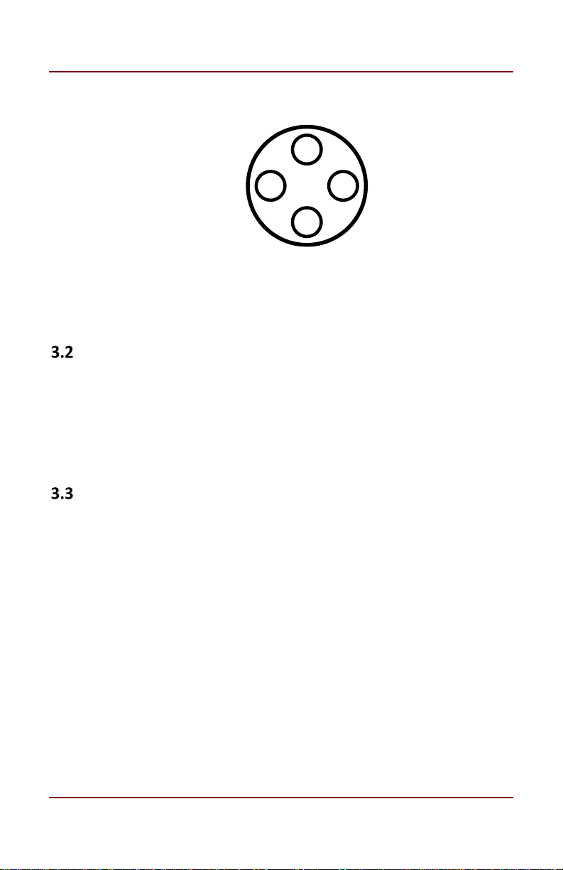
The four sockets comprising the laser diode connector are
through‐hole type sockets with a blind clearance of 0.48”
(1.22cm)measuredfromthefrontfaceofthecoppercoldplate.
Itisnotnecessarytotrimthelaserdiodeleadspriortomounting
intothisconnectorunlesstheyarelongerthan0.48”(1.22cm).
Thelaserconnectorislocatedcloseenoughtothefrontfaceof
thecoppercoldplatetoalloweasyinstallationofshort‐leaded
lasers. The clearance area around the LD and PD sockets is
sufficienttopreventthepinsfromcontactingthecoldplate.
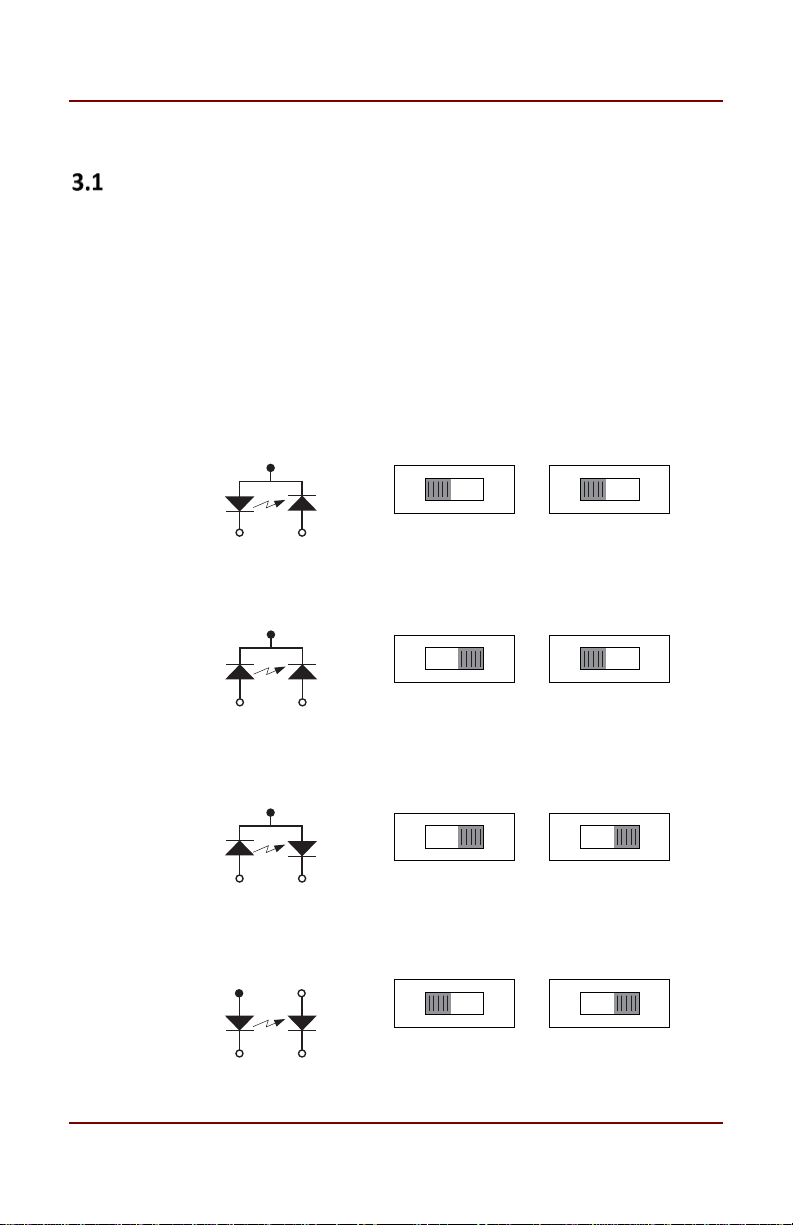
Mostlaserdiodesarethreepinswiththecasetiedtooneofthe
laserpinsandalsotooneofthephotodiodepins.Theotherlaser
and photodiode pins will be isolated from the case. The
LDM21(/M) was designed to operate the laser case at ground
potential,thereforethiscommonpinwillbeinsertedintoeither
the12o’clockorthe6o’clockpositionofthelaserconnector.
Locatetheisolatedlaserpinandinsertitinthe3o’clockposition.
Theisolatedphotodiodeshouldnowbeinthe9o’clockposition.
Refer to Fig. 3. (Orient the mount with the PD polarity switch
abovetheLDsocket).
TheLDM21(/M)MountisalsocompatiblewithstyleEandstyle
Hlaserdiodes,whichdonothaveaphotodiode;theyhaveonly
alaserdiodeandagroundpin.Theycanthereforebesetupthe
same as style A (LD Anode Ground) or style B (LD Cathode
Ground)respectively.
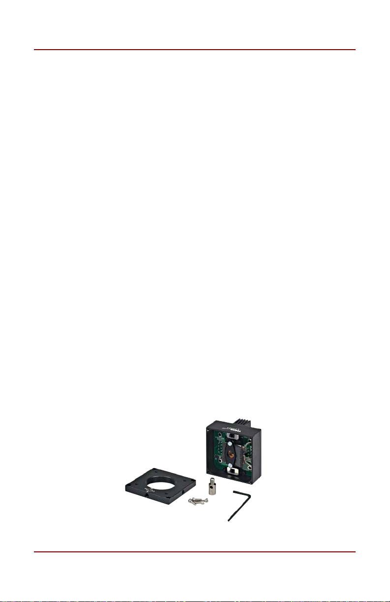
Replace the laser mounting flange and the cover. Install both
screwsthroughthemountingflangeandlooselyintothemount.
Carefullytighteneachscrewalittlebitatatimeuntiltheflange
isjustsnug.Donotover‐tighteneitherscrew‐theflangeshould
sitslightlyabovethecoldplate.Reinstallthecoverusingthefour
2‐56capheadscrewsprovided.

5.6mm/9mmLaserDiodeMount Chapter3:Setup
Rev.L,March23,2023 Page5
Figure3 LDandPDOrientation
5.6mmAdapter
Bydefault,theLDM21(/M)isdesignedtobeusedwithstandard9mm
laserdiode packages.Themountcanbeusedwithastandard 5.6mm
using the included adapter, which can be found in the small brown
envelopemarked“Accessories”ontheoutside.Includedinthisenvelope
isthe9mmmountingplateandtheimperialtometricmountingadapter.
4‐PinLaserDiodes
TheLDM21(/M)alsosupports4‐pinlaserdiodes.Insertthelaserintothe
4‐pinsocketandnotewhichlaserpinisinthe3o’clockposition(laser
anodeorcathode). Also note whichphotodiode pin is inthe9 o’clock
position(anodeorcathode).Themountwilltiethelaserandphotodiode
pinslocatedat12o’clockand6o’clocktogetherandalsotoground.By
notingwhichpolaritypinsareinsertedintothesocket,youcanconvert
the4‐pinlayouttooneofthe3‐pinlayoutsinFigure2onpage3.Setthe
LDandPDpolarityswitchesaccordingly.
G
G
LDPD

5.6mm/9mmLaserDiodeMount Chapter3:Setup
Page6 TTN013394‐D02
LaserControllerConnections
UsingtheThorlabsLDC/ITCSeriesLaserControllers:
TheLDM21(/M)iscompatiblewithallThorlabsLDCLD
controllersandITCseriescombinationcontrollers(LDandTEC).
Appropriate cables with DB9 connectors are included with
Thorlabs controllers and ensure that the controllers cannot be
connectedincorrectly.Additionally,thesecontrollershavebuilt‐
inprotectioncircuitrythatprotectsthelaserwhennotinuse.
ThenomenclaturefortheLaserDiodepolarityswitchonthe
LDC/ITC driver and the LDM21(/M) are consistent with each
other.Forexample,ifthelaserpolarityonthedriverissetto
“AG” (anode grounded), then the LD polarity switch on the
LDM21(/M)shouldalsobesettoAG,andsoforth.
ThenomenclatureforthePhotoDiodepolarityswitchonthe
LDC4000SeriesBenchtopControllers,PRO8LaserDiodeCurrent
ControlModules,andITCseriesdriversandtheLDM21(/M)isas
follows:ThephotodiodepolarityswitchontheLDM21(/M)must
alwaysbesetto“CG”.Thephotodiodepolarityshouldbesetwith
theinternalLasercontrollerswitchonly.Formoreinformation
onhowtosetPolaritysettingsontheLasercontroller,please
refertotheappropriateLaserControllermanual.
Usingathird‐partylasercontroller:
Whenusingathird‐partycontroller,acustomcablewillhaveto
bemadetoproperlyinterfacetothelasermount.Pleasereferto
thetableonthenextpageforlaserconnections:

5.6mm/9mmLaserDiodeMount Chapter3:Setup
Rev.L,March23,2023 Page7
Pin Signal Description
1Interlock
(LDCSpecific)
ThispinistheinputtotheInterlockCircuits.
WhenusingThorlabsLDCs,noexternalcircuitry
isrequired.
2Photodiode
Cathode
Thispinisconnectedtothe9o’clockpinonthe
lasersocketwhenthePDPolaritySwitchissetto
AG(AnodeGrounded).Itisattachedtoground
andthe12o’clockand6o’clockpinsonthelaser
socketwhenthePDPolaritySwitchissettoCG
(CathodeGrounded).
3LaserGround
(Case)
Thispinisconnectedtothe12o’clockand6
o’clockpinsonthelasersocketandcorresponds
tothesettingsoftheLDandPDpolarity
switches.i.e.,iftheLDandPDswitchesareset
toAG,thenthispingroundstheAnodesofthe
laserandphotodiode.
4 Photodiode
Anode
Thispinisconnectedtothe9o’clockpinonthe
lasersocketwiththePDPolaritySwitchissetto
CG(CathodeGrounded).Itisattachedtoground
andthe12o’clockand6o’clockpinsonthelaser
socketwhenthePDPolaritySwitchissettoAG
(AnodeGrounded).
5 Interlock
Return
ThispinisthereturnsideoftheInterlock
circuitry.Pins1and5areshortedinternallyin
theLDM21(/M).
6 N/A
7 LaserDiode
Cathode
Thispinisconnectedtothe3o’clockpinonthe
lasersocketwhentheLDPolaritySwitchissetto
AG(AnodeGrounded).Ifthepinisnot
connected,itwillbefloating
8 LaserDiode
Anode
Thispinisconnectedtothe3o’clockpinonthe
lasersocketwhentheLDPolaritySwitchissetto
CG(CathodeGrounded).Ifthepinisnot
connected,itwillbefloating
9 N/A

5.6mm/9mmLaserDiodeMount Chapter3:Setup
Page8 TTN013394‐D02
TECControllerConnections
UsingtheThorlabsTEDSeriesTECControllers:
TheLDM21(/M)isbestusedwithThorlabsTED200Correlated
TECControllers.TheTEDseriesareshippedwithamatingDB9
cable that plugs directly into the controller and laser mount.
UsingthecablesuppliedwiththeTED,thecontrollercannotbe
connected incorrectly. Simply connect the cable included with
theTEDtotheLaserMountandtothecontroller.
Usingathird‐partyTECcontroller:
Whenusingathird‐partycontroller,acustomcablewillhaveto
bemadetoproperlyinterfacetothelasermount.Pleasereferto
thetablebelowforlaserconnections.
Pin Signal Description
1 N/A N/A
2 Thermistor(+) The10kΩ@25°CNTCthermistor(providedfor
temperaturefeedback).
3 Thermistor(‐) Thethermistorreturnpin
4 TEC(+) ThispinisconnectedtothepositiveterminaloftheTEC
element.
5 TEC(‐) ThispinisconnectedtothenegativeterminaloftheTEC
element.
6 N/A N/A
7 AD592(‐)
ThenegativeterminaloftheAD592temperature
transducer.WhenusingThorlabsTEDs,noexternal
circuitryisrequired.Tousethisdevicewiththirdparty
controllers,itmustbeproperlybiased.RefertoAnalog
DevicesAD592Dataforapplicationinformation.
8 N/A N/A
9 AD592(+) ThepositiveterminaloftheAD592

5.6mm/9mmLaserDiodeMount Chapter3:Setup
Rev.L,March23,2023 Page9
ThermistorData
Figure4 ThermistorCurveandData
Resistance(Ω) °C Resistance(Ω) °C
15895 15 9563 26
15153 15 9149 27
14451 17 8755 28
13785 18 8380 29
13155 19 8023 30
12558 20 7684 31
11991 21 7362 32
11454 22 7055 33
10944 23 6762 34
10460 24 6484 34
10000 25

5.6mm/9mmLaserDiodeMount Chapter3:Setup
Page10 TTN013394‐D02
3.6.1 TheoreticalResistanceValues
The relationship between resistance and temperature can also be
calculatedusingthefollowingequations.
𝑅
𝑅
𝑒
//
⁄
𝑇
𝐴
𝐵
ln 𝑅
𝑅
𝐶
ln
𝑅
𝑅
𝐷
ln
𝑅
𝑅
WhereA,B,C,D,A
1
,B
1
,C
1
,andD
1
areconstantvaluesthatdependon
thematerial;seetablebelowforvalues.R
ref
istheresistancevalueata
referencetemperature,whichisroomtemperatureinthiscase.Tisthe
temperatureinK.
Constants Value Unit
A ‐14.6337 ‐
B 4791.842 K
C ‐115334 K
2
D 3.730535E+06 K
3
A
1
3.354016E‐03 ‐
B
1
2.569850E‐04 K
‐1
C
1
2.620131E‐06 K
‐2
D
1
6.383091E‐08 K
‐3
T
0
298.15 K
R
ref
10000 Ω
MountingOtherAccessories
TheLDM21(/M)includesaSM1threadedholecenteredonthelaserfor
mountingThorlabsSM1‐seriesopticmounts.Thisismostoftenusedfor
mountingasphericcollimatingopticsavailableseparatelyfromThorlabs.

5.6mm/9mmLaserDiodeMount Chapter3:Setup
Rev.L,March23,2023 Page11
Alsoincludedarefour4‐40tappedholesmountedon30mmcentersfor
attachingourcageassemblyproducts.UsingthecombinationoftheSM1
threaded mount and the cage assemblies’ products, a wide variety of
opticalsystemscanbeeasilyassembledfromoff‐the‐shelfproducts.

5.6mm/9mmLaserDiodeMount Chapter4:Operation
Page12 TTN013394‐D02
Chapter4 Operation
Withthelasermountedandthelaserandtemperaturecontroller
connected,theLDM21(/M)isreadytooperate.Pleasereferto
theoperatinginstructionsforthelaserandtemperature
controllerforspecificoperatinginstructions.
Whenoperatingatlowtemperaturesinhighhumidityclimates,
the laser mount may develop internal condensation. If this
occurs,turnthelaseroff,openthecase,andallowthemountto
dryoffcompletelybeforere‐using.
Whenusingacollimatingopticinthe1"threadedmount,thelens
may be positioned slightly laterally by loosening the four 2‐56
screwsonthecoverandshiftingthecoverplatemanually.
SafeOperatingArea
TheLDM21(/M)isintendedtobeoperatedatafixedtemperatureset‐
pointof25°Cbutcanbeoperatedaslowas20°Caslongastheinput
powertothelaserdiode(inputcurrentxLDvoltage)doesnotexceedthe
valuesspecifiedintheSafeOperatingAreacurveasafunctionofambient
temperature.ItisnotrecommendedthattheLDM21(/M)bedrivenwith
morethan600mWofinputpower,settoatemperaturebelow20°C,or
operatedinanambienttemperatureabove35°C.Operatingthe
LDM21(/M) outside of the safe operating area will result in thermal
runaway of the cooling system which will damage the laser diode
mountedintheunit.
Additionally, the 2 W maximum cooling capacity includes the power
dissipatedbytheTECelementinadditiontotheinputpowerofthelaser
diode.CarefulmonitoringoftheTECpower(TECCurrentxTECVoltage)
alongwiththeparametersoftheSOAcurvewillfurtherensurethatthe
systemisoperatingwithinitscapabilities.

5.6mm/9mmLaserDiodeMount Chapter4:Operation
Rev.L,March23,2023 Page13
MaintainingtheLDM21(/M)
TherearenoserviceablepartsintheLDM21(/M).Thehousing maybe
cleanedbywipingwithasoftdampcloth.Ifyoususpectaproblemwith
yourLDM21(/M),pleasecallThorlabsTechnicalSupport,andanengineer
willbehappytoassistyou.

5.6mm/9mmLaserDiodeMount Chapter5:Troubleshooting
Page14 TTN013394‐D02
Chapter5 Troubleshooting
1. LaserDriverwillnotenable.
If you are using our laser and TEC controllers with our
LDM21(/M) mount, make sure that both cables are fully
insertedintotheirDB9connectors.
2. Laser wavelength or power is unstable even though the TEC
controllershowsastabletemperature.
Make sure that your laser diode is fully inserted into the
LDM21(/M)lasersocketandthatitsbodyisinfullcontact
withthecoppercoldplate.
Makesurethattheappropriatemountingflangeisinstalled
over your laser. There are two different flanges; one
specificallyfor5.6mmdiodesandonefor9mmdiodes.
3. TheLDCserieslaserdriverindicatesan“OpenCircuit”alarm
whenItrytoenablethelaser.
TheLDandPDpolarityswitchsettingsareincorrect.Referto
Fig.1andthedatasheetforyourspecificlaserdiodeto
ensurethepropersettings.TheLDpolarityswitchsettingon
yourLDM21(/M)mustalsomatchtheLDpolarityswitchon
therearpanelofyourLDCserieslaserdiodecontroller.
Thelaserdiodeisinstalledintothewrongpinsonthelaser
diodesocket.RefertoFig.2forthecorrectorientationofthe
laserdiodepinsandcomparethistothedatasheetforyour
laserdiode.
4. My laser diode does not have an integrated photodiode. How
doesitgetinstalled,andhowdothepolarityswitchesgetset?
Ifyourlaserdiodehasoneofitstwoactiveleadscommonto
thecaseofthelaser,thatleadmustbeconnectedtooneof
the“G”socketsonthelaserdiodeconnector(refertoFig.2)
whiletheotherpinisconnectedtothe“LD”socketinthe3
o’clock position. Depending on the pin orientation of your
laser,youmightbeusingeitherthe“G”socketat12o’clock

5.6mm/9mmLaserDiodeMount Chapter5:Troubleshooting
Rev.L,March23,2023 Page15
orthe“G”socketat6o’clock.Refertoyourlaserdiodedata
for pin orientation. If your cathode pin is common to the
bodyofyourlaserdiode,settheLDpolarityswitchto“CG”.
Ifyouranodepiniscommontothebodyofyourlaserdiode,
set the LD polarity switch to “AG”. The setting for the PD
polarityswitchisirrelevant.
Ifyoustillhaveproblemsorquestionsregardingtheoperationofyour
LDM21(/M),pleasecontactThorlabsTechSupport.

5.6mm/9mmLaserDiodeMount Chapter6:Specifications
Page16 TTN013394‐D02
Chapter6 Specifications
Item# LDM21(/M)
General
Size 1.75"x1.75"x1.66"
(44.5mmx44.5mmx42.1mm)
Weight 3oz(0.08kg)
AccessoryMounting
1.035"‐40ThreadforSM1SeriesOpticsMounts
4‐40x30mmTappedHolesforCageAssembly
Products
MountingHoles LDM21:8‐32orLDM21/M:M4
LaserSpecifications
LasersSupported 5.6mmand9mm
MaxLaserCurrent 500mAa
MaxLaserInputPower 600mWa
LaserPin Ø5.6andØ9.0mmLaserDiodes
A,B,C,D,E,andHConfigurations
Configurations Selectable
LaserPolaritySelect SlideSwitches
LaserInterface DB9Female
TECSpecifications
MaxTECCurrent 2.5A
MaxTECVoltage 1.8V
TECHeating/
CoolingCapacity 2W
TypicalTemperatureRange(LDdependent)
TemperatureRange 20–30°C
TempSensor1
Thermistor
10kΩ±3%,NTC
Beta=3977K±0.75%
TempSensor2
AnalogDevicesAD592 1µA/K
TECInterface DB9Male
a.SeeSafeOperatingAreaonpage14formoreinformation.
Other manuals for LDM21
1
This manual suits for next models
1
Table of contents
Other THORLABS Lighting Equipment manuals

THORLABS
THORLABS OSL2 User manual

THORLABS
THORLABS M405LP1 User manual

THORLABS
THORLABS SLS201L User manual

THORLABS
THORLABS LEDD3 Series User manual

THORLABS
THORLABS PSY240E User manual

THORLABS
THORLABS S5FC Series User manual

THORLABS
THORLABS LED4C Series User manual

THORLABS
THORLABS CHROLIS User manual

THORLABS
THORLABS M365L1 User manual

THORLABS
THORLABS SLS303 User manual