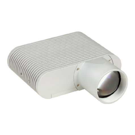
THORLABS SLS401 User manual

SLS401 & SLS402
Benchtop Arc Lamp
User Guide

Benchtop Arc Lamp
Table of Contents
Chapter 1Warning Symbol Definitions..............................................................................................1
Chapter 2Safety....................................................................................................................................2
Chapter 3Product Overview................................................................................................................3
3.1.Planck's Law and Black Body Radiation.......................................................................3
3.2.Xenon and Mercury Xenon Arc Lamp ...........................................................................4
3.3.Optical Configuration......................................................................................................4
Chapter 4Getting Started.....................................................................................................................7
4.1.Part List ............................................................................................................................7
4.2.Unpacking ........................................................................................................................7
4.3.Operation Elements ........................................................................................................8
4.3.1.Lamp Housing Front and Back Panels .................................................................................8
4.3.2.Controller Front Panel ...........................................................................................................8
4.3.3.Controller Back Panel ...........................................................................................................9
4.4.Bulb Handling ..................................................................................................................9
4.5.Bulb Installation ............................................................................................................10
4.6.Setting Up on a Work Surface......................................................................................13
Chapter 5Operation.............................................................................................................................16
5.1.Starting the Lamp..........................................................................................................16
5.2.Shutter Operation..........................................................................................................16
5.3.Adjusting Collimation ...................................................................................................16
5.4.Adjusting the Rear Concave Mirror .............................................................................17
5.5.Application Ideas...........................................................................................................18
5.6.Troubleshooting ............................................................................................................19
5.6.1.Overheating.........................................................................................................................19
5.6.2.Lamp Not Connected ...........................................................................................................19
5.6.3.Bulb State Warning .............................................................................................................19
Chapter 6Bulb Replacement..............................................................................................................20
Chapter 7Specifications.....................................................................................................................21
Chapter 8Mechanical Drawing...........................................................................................................22
Chapter 9Certifications and Compliances.......................................................................................23
Chapter 10Regulatory...........................................................................................................................24
Chapter 11Thorlabs Worldwide Contacts..........................................................................................25
Benchtop Arc Lamp Chapter 1: Warning Symbol Definitions
Rev C, September 28, 2018 Page 1
Chapter 1 Warning Symbol Definitions
Below is a list of warning symbols you may encounter in this manual or on your device.
Symbol Description
Direct Current
Alternating Current
Both Direct and Alternating Current
Earth Ground Terminal
Protective Conductor Terminal
Frame or Chassis Terminal
Equipotentiality
On (Supply)
Off (Supply)
In Position of a Bi-Stable Push Control
Out Position of a Bi-Stable Push Control
Caution: Risk of Electric Shock
Caution: Hot Surface
Caution: Risk of Danger
Warning: Laser Radiation
Caution: Spinning Blades May Cause Harm

Benchtop Arc Lamp Chapter 2: Safety
Page 2 CTN002644-D02
Chapter 2 Safety
The lamp comes with a switching power supply compatible with voltages from 100 to 240 VAC. There is no need
to change the fuse when selecting your regional voltage.
SHOCK WARNING
High voltage inside. To avoid electrical shock, before powering unit, make sure that the protective
conductor of the 3-conductor power cord is correctly connected to the protective earth contact of the
socket outlet. Improper grounding can cause electric shock resulting in severe injury or even death.
Do not operate without cover installed.
WARNING
This unit must not be operated in explosive environments.
WARNING
Do not operate in wet/damp conditions.
WARNING
Do NOT look directly at the light source beam during operation. Do NOT place hand or body part in
the light beam as this may cause burning.
CAUTION: HOT SURFACE
The housing of the lamp housing can get very hot during operation.
Extensive contact may cause burning.
WARNING: HOT SURFACE
The temperature of the bulb will exceed 200˚C during operation. Always wait for at least 30 minutes
for the bulb to cool down before performing a bulb replacement. Always wear gloves
when handling bulbs.

Benchtop Arc Lamp Chapter 3: Product Overview
Rev C, September 28, 2018 Page 3
Chapter 3 Product Overview
3.1. Planck's Law and Black Body Radiation
A black body is an object that absorbs all incident electromagnetic radiation (e.g., light): no light passes through or
is reflected. However, despite the name, a black body will also emit electromagnetic radiation. The radiation of a
black body in thermal equilibrium is described by Planck’s Law:
, 2
1
1
Where
I
is the radiated power per unit area of emitting surface per unit wavelength at temperature
T
;
K
is the
Boltzmann constant,
h
is the Planck constant,
c
is the speed of light.
By measuring the spectrum of the black body radiation, we can calculate the temperature of this black body. Figure
1 shows the radiated power per unit area I as a function of wavelength at various temperatures.
Figure 1 Blackbody Radiation at Different Temperatures
In real life, broadband light sources may vary widely from the ideal black body in terms of the frequency and intensity
of the light emitted. By comparing the light source to an ideal black body at a given temperature, one can
characterize the light source by the temperature of the black body radiator which has the same chromaticity, which
is known as the color temperature of the light source.

Benchtop Arc Lamp Chapter 3: Product Overview
Page 4 CTN002644-D02
3.2. Xenon and Mercury Xenon Arc Lamp
An arc lamp is a light source that generates light from gas discharge. The construction of a double ended arc lamp
bulb is shown in Figure 2. The bulb consists of two metal electrodes sealed in a quartz envelope that is filled with
inert gas.
Figure 2 Structure of a Double-Ended Arc Lamp Bulb
During ignition, high-voltage pulses are sent through the electrodes to ionize the gas in between, causing arc
discharge to occur. After the arc discharge has been initiated, only a low voltage is required to maintain it. During
arc discharge, pinpoint-sized cloud of plasma in the arc will generate light with very high brightness.
Thorlabs offers both Xenon and Mercury-Xenon Arc Lamps. Both bulbs are filled with Xenon gas, while the Mercury-
Xenon bulb has traces of mercury mixed in. The Xenon arc lamp provides a continuous emission over the 240 nm
to 2400 nm spectral region with some intense lines between 800 nm and 1000 nm. A Mercury-Xenon arc lamp
provides higher peaks at the blue and UV end of the spectrum due to the characteristic spectral lines of Mercury.
The SLS401 Xenon arc lamp has a nominal color temperature of 5800 K and the SLS402 Mercury-Xenon arc lamp
has a nominal color temperature of 6000 K. Figure 3 provides the typical spectra of Xenon and Mercury-Xenon
lamps.
Figure 3 Spectra of Xenon (left) and Mercury-Xenon (right) Lamps
3.3. Optical Configuration
The SLS401 is a Xenon Arc lamp with a 150 W Xenon bulb. SLS402 is a Mercury Xenon Arc lamp with a 150 W
Mercury-Xenon bulb. The bulb is placed inside the lamp housing at the back focal point of the collimating lens, with
Quartz Envelope
Anode
Cathode

Benchtop Arc Lamp Chapter 3: Product Overview
Rev C, September 28, 2018 Page 5
the long axis of the arc aligned vertically and parallel to the plano surface of the lens, to produce a collimated output
beam.
There is a silver-coated concave mirror at the rear of the lamp housing, with its center of curvature aligned with
center of the arc lamp bulb, as shown in Figure 4. This configuration focuses the light from arc back back to the arc
position so that it can be be collimated by the front lens.
Figure 4 gives an outline of the optical configuration of the Arc lamp.
Figure 4 Basic Optical Configuration of SLS401 and SLS402 Lamps
Here are the dimensions of the bulbs.
Bulb Specifications
Dimensions
A 125 mm
B 150 mm
C 58 mm
Arc Gap 1.9 mm
Figure 5 Xenon and Mercury-Xenon Bulb Dimensions
Bulb Lens
Back Focal Length
Rear Mirror
Radius of Curvature
A
B
+
-
C

Benchtop Arc Lamp Chapter 3: Product Overview
Page 6 CTN002644-D02
The collimating lens is a plano-convex aspherical lens, with the plano surface facing the arc. The main specifications
of the collimating lens are listed below.
Lens Specifications
Parameter Symbol Value
Clear Aperture CA 35 mm
Diameter Dia 38 mm
Focal Length f 79.16 mm
Back Focal Length fb73.68 mm
Center Thickness tc8 mm
Edge Thickness te2.87 mm
Material UV-Grade Fused Silica
Design Wavelength 587.6 nm
Figure 6 Collimating Lens Specifications
The silver-concave mirror is oriented with the coated, concave surface facing the arc. The main specifications of
the collimating lens are listed below.
Mirror Specifications
Parameter Symbol Value
Diameter Dia 50.8 mm
Focal Length f 38.1 mm
Radius of Curvature ROC 76.2 mm
Center Thickness tc9 mm
Edge Thickness te13.3 mm
Material N-BK7
Coating Protected Silver
Figure 7 Rear Mirror Specifications
H"
Dia
t
e
t
c
f
b
f
f
f
R
f
t
Diameter
e
ROC
tc

Benchtop Arc Lamp Chapter 4: Getting Started
Rev C, September 28, 2018 Page 7
Chapter 4 Getting Started
4.1. Part List
The package contains the following items:
1 Lamp Housing
1 Controller Unit
1 Bulb
1 Operation Manual
1 Cable for Connecting Lamp Housing and Controller
1 Power Cord
1 4 mm Hex Key
1 1.3 mm Hex Key
4.2. Unpacking
The packaging of the SLS401 and SLS402 is illustrated below.
Figure 8 Packaging of the SLS401 and SLS402 Lamps
There are 6 major pieces of foam inserts in the packaging of an SLS401 or SLS402 as shown in Figure 8. Remove
them carefully and take out the lamp and controller.
Controlle
r
Lam
p
House
Lam
p
Control Cable
Power Cord

Benchtop Arc Lamp Chapter 4: Getting Started
Page 8 CTN002644-D02
4.3. Operation Elements
4.3.1. Lamp Housing Front and Back Panels
Figure 9 Front and Back Panel of SLS401 or SLS402 Lamp Housing
L1. Shutter Control Knob
L2. Collimating Lens
L3. 4-40 Threaded Hole for 60 mm Cage Systems
L4. Adjustable Feet
L5. Knobs for Adjusting Rear Concave Mirror Alignment
4.3.2. Controller Front Panel
Figure 10 Front Panel of Arc Lamp Controller
C1. Power Switch
C2. Lifetime Reset Button
C3. Bulb Status Indicator LED
C4. Temperature Warning LED
C5. LCD Screen
C4
C3
C1
L5
L3
L1
L2
L4
C2 C5

Benchtop Arc Lamp Chapter 4: Getting Started
Rev C, September 28, 2018 Page 9
4.3.3. Controller Back Panel
Figure 11 Back Panel of Arc Lamp controller
C5. Cooling Fan
C6. Connector for Lamp Control Cable
C7. USB Connector (Reserved for Future Firmware Updates)
C8. Power Connector
4.4. Bulb Handling
WARNING
Always wear protective gloves when handling the bulb. Moisture and grease from hands left on the
bulb may affect the integrity of the bulb envelope, shortening the bulb lifetime. At worst, it could
cause the bulb to explode.
WARNING
The bulb contains compressed gas and may explode if the integrity of the glass envelope is
compromised. Always wear splinter-proof eyewear when handling the bulb.
The bulb of an arc lamp requires caution during handling. When handled correctly, the bulb is a very safe instrument.
However, improper handling may cause hazard to users.
The bulb of an arc lamp contains high internal pressure and would burst if handled incorrectly even when not in
operation, causing serious injuries. Always wear eye/face and body protection when handling a bulb. Never bump,
drop, apply excessive stress, or scratch the bulb.
Please always wear protective gloves when handling the bulb. Moisture and grease from hands left on the bulb may
affect the integrity of the bulb envelope, shortening the bulb lifetime. At worst, it could cause the bulb to burst.
Please only hold the bulb at its electrodes. Avoid holding the bulb at the glass envelope.
Keep the glass envelope clean at all times. If needed, clean any dirt, oil, or lint away from the bulb with alcohol and
a lint free cloth or tissue
When not using, always put the bulb in its original package and seal it.
C8
C5
C6
C7

Benchtop Arc Lamp Chapter 4: Getting Started
Page 10 CTN002644-D02
The temperature of the bulb may reach a few hundred degrees Celsius during operation. Always wait at least 30
minutes for the bulb to cool down before handling the bulb after operation.
Make sure that the bulb is always installed with the correct direction and polarity.
4.5. Bulb Installation
WARNING
Always power off the unit before opening the lamp housing.
WARNING
The bulb surface temperature may reach a few hundred °C during operation. Always wait at least 30
minutes after turning off the lamp for cool down before performing a bulb replacement.
WARNING
Always wear protective gloves when handling the bulb. Moisture and grease from hands left on the
bulb may affect the integrity of the bulb envelope, shortening the bulb lifetime. At worst, it could
cause the bulb to explode.
Take the lamp out of its packaging and place it onto a table top. Locate the removable side panel indicated by the
engraving on top cover of the lamp.
Figure 12 An engraving on the top cover indicates the removable side panel.
Only this side can be opened.

Benchtop Arc Lamp Chapter 4: Getting Started
Rev C, September 28, 2018 Page 11
Use a 4 mm hex key or ball driver to remove the four cap screws on the corners of the side plate, then remove the
side plate.
Figure 13 Removing the Side Plate
The SLS401/402 is equipped with a dummy bulb to secure the top bulb holder during transportation. Loosen the
thumb screws on top and bottom bulb holder by turning counterclockwise and remove the dummy bulb. Keep the
dummy bulb for future use.
Carefully take out the bulb from its original package. ALWAYS hold the bulb at its electrodes. Avoid holding the
glass envelope. Always wear protective gloves when handling the bulb.
Figure 14 Taking the Bulb out of its Original Package

Benchtop Arc Lamp Chapter 4: Getting Started
Page 12 CTN002644-D02
Insert the bulb into the bottom bulb holder. MAKE SURE THAT THE ANODE IS POINTING UP. Trying to ignite a
bulb installed upside-down may cause damage to the bulb and the controller.
Figure 15 Insert the bulb with anode pointing up.
Install the upper bulb holder on the anode. Make sure the anode is securely inserted into the holder and then tighten
both thumb screws by turning clockwise.
Figure 16 Secure the Bulb
After the bulb is installed, put the side plate back onto the housing and tighten the four cap screws on the corners
of the side plate. Please keep the original box for the bulb for future storage of a used bulb.
Thumbscrews
A
node
Cathode

Benchtop Arc Lamp Chapter 4: Getting Started
Rev C, September 28, 2018 Page 13
4.6. Setting Up on a Work Surface
All four feet on the lamp housing are height adjustable to compensate for any unevenness of a work surface. To
adjust the height, use a 4 mm hex key (one is included with the SLS401 and SLS402) to loosen and remove the
cap screws.
Figure 17 Removing Caps from the Adjustable Feet
Use a 10 mm wrench (not included) to rotate the washer underneath the bottom plate. Press lightly on the plastic
feet to make sure that they do not rotate together with the washer. A counterclockwise rotation will increase the
height. All feet are set to minimum height by default.
Figure 18 Adjusting the Height of the Supporting Feet

Benchtop Arc Lamp Chapter 4: Getting Started
Page 14 CTN002644-D02
The lamp also allows direct mounting to an optical breadboard or table. It is compatible with both metric and
imperial breadboards/tables. Simply remove all four feet with a 4 mm hex key and use M6 or 1/4"-20 cap screws
(not included in the package) to secure the bottom plate to a working surface.
Figure 19 Lamp house mounted on a breadboard

Benchtop Arc Lamp Chapter 4: Getting Started
Rev C, September 28, 2018 Page 15
Connect the lamp cable to both the lamp housing and controller. Please notice that there is an arrow marker on
both the plug and the socket. Make sure those two makers are in line with each other, then lightly press the
connector onto the socket and turn the threaded cap screw clockwise to lock the connector using the included
1.3 mm hex key. To remove the cable, press the connector against the socket lightly and turn the cap screw
counterclockwise to unlock the connector.
Figure 20 Connecting the Lamp Control Cable
Plug the power cable into the power socket and the unit is ready to use.
WARNING
Always ensure the unit is powered off before connecting or disconnecting the lamp cable. Failing to
do so could damage the lamp.

Benchtop Arc Lamp Chapter 5: Operation
Page 16 CTN002644-D02
Chapter 5 Operation
5.1. Starting the Lamp
The front panel of the controller is shown in Figure 21. Make sure both the power cable and the lamp control cable
are securely connected, then press power switch (C1) to turn on the lamp.
After the lamp is turned on, the two LEDs on the front panel will show the state of the lamp. Under normal operation,
both LEDs will be GREEN.
The LCD screen will show the type and wattage of the bulb. For the SLS401 and SLS402, the bulb type will show
as SLS400 regardless of which bulb is installed (Xenon or Mercury Xenon). On the left corner of the screen, a timer
will count down the hours left in the bulb’s lifetime. On the right corner of the screen, an error message will appear
if there is any error during the operation of the lamp.
Figure 21 Front Panel of the SLS401 or SLS402 Controller During Operation
Please be advised that 2000 hours is just the typical lifetime of a bulb. The end of lifetime is defined as the time
when the output optical power of the bulb reaches half of its initial value. The actual life time value varies between
individual bulbs. The timer provides a reference of how much time may be left on the current bulb based on the
typical lifetime.
After switching the lamp on, please allow a 45 to 60 minute warm up period for the lamp to reach a stable state.
After shutting the lamp down, allow at least 30 minutes for the bulb to cool down before switching the lamp back
on. A hot bulb cannot be ignited by the controller, leading to a bulb state warning.
CAUTION
The surface of the lamp housing may get hot during operation. The temperature may reach ~60 °C.
Avoid extensive contact with the lamp housing.
5.2. Shutter Operation
The lamp comes with a manual shutter. Simply turn the knob (L1 shown in Figure 9) clockwise to turn the shutter
into the open position. Turning it counterclockwise sets the shutter to a closed position.
5.3. Adjusting Collimation
The front lens (L2 shown in Figure 9) is pre-adjusted to achieve the best collimation. Users can also adjust the
position of the lens to change the collimation themselves.

Benchtop Arc Lamp Chapter 5: Operation
Rev C, September 28, 2018 Page 17
As shown in Figure 22, loosen the locking ring and then turn the lens tube to change the lens position: clockwise to
move closer to bulb or counterclockwise to move further away from bulb. Thorlabs' SPW503 Spanner Wrench (sold
separately) can be used to easily loosen or tighten the SM2 locking ring.
Figure 22 Adjusting the Collimating Lens Position
5.4. Adjusting the Rear Concave Mirror
The concave mirror is shipped preset in the optimum position. If adjustment is required, remove the side plate as
instructed in Section 4.4 to reveal the rear mirror.
The mirror is mounted on a kinematic mirror mount with its three adjusters locked prior to shipping. Use a 5/64" or
2 mm hex key to loosen the three locking screws on the mirror mount, then close the lamp housing by putting back
the side plate.
Figure 23 Locking screws on the rear mirror mount
Now the mirror is adjustable. Use the three knobs on the back panel for mirror adjustment.

Benchtop Arc Lamp Chapter 5: Operation
Page 18 CTN002644-D02
Figure 24 Adjustment Knobs on the Back Panel
5.5. Application Ideas
As shown in Figure 9, there are four 4-40 threaded holes on the front panel of the lamp house to allow the integration
of Thorlabs 60 mm Cage System. The collimating lens also has internal SM2 threads to allow the integration of
Thorlabs SM2 mounts and lens tubes.
Figure 25 shows an application idea of how to integrate the SLS401 with Thorlabs’ 60 mm cage system and an
SM2 lens tube.
Figure 25 SLS401 with an SM2 Lens Tube and 60 mm Cage System
This manual suits for next models
1
Table of contents
Other THORLABS Lighting Equipment manuals

THORLABS
THORLABS M365L1 User manual

THORLABS
THORLABS LDM21 User manual

THORLABS
THORLABS S5FC Series User manual

THORLABS
THORLABS SLS303 User manual

THORLABS
THORLABS PSY240E User manual

THORLABS
THORLABS CHROLIS User manual

THORLABS
THORLABS MCWHF2 User manual

THORLABS
THORLABS LED4C Series User manual

THORLABS
THORLABS M405LP1 User manual

THORLABS
THORLABS DC3100 Series User manual