THORLABS SLS205 User manual

SLS205
75 W Xenon Light Source
User Guide

75 W Xenon Light Source
Table of Contents
Chapter 1 Warning Symbol Definitions ...........................................1
Chapter 2 Safety.................................................................................2
Chapter 3 Product Overview.............................................................4
3.1. Xenon Light Source ........................................................ 4
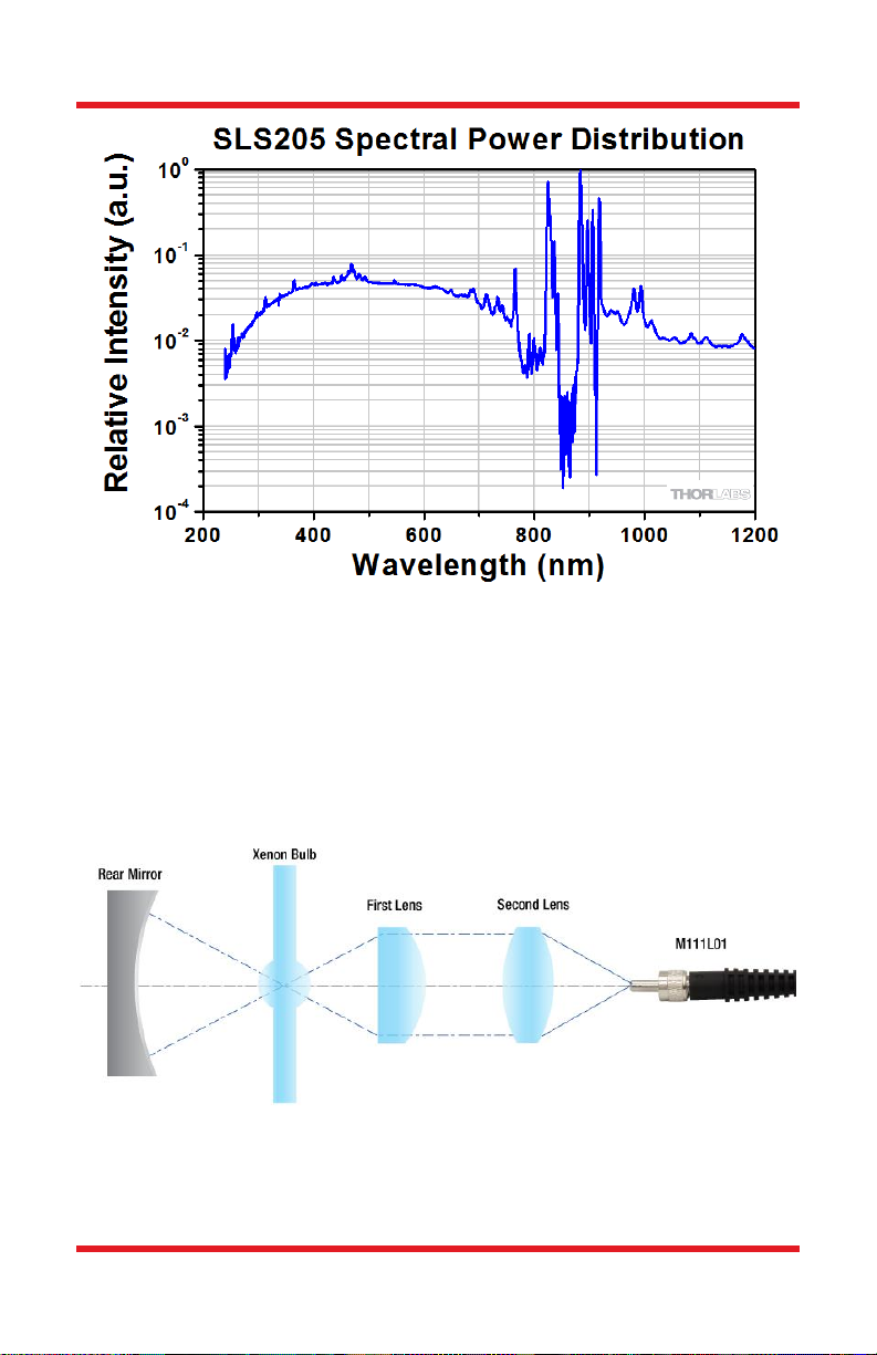
3.2. Spectrum ....................................................................... 4
3.3. Optical Configuration .................................................... 5
Chapter 4 Operation...........................................................................6
4.1. Parts List........................................................................ 6
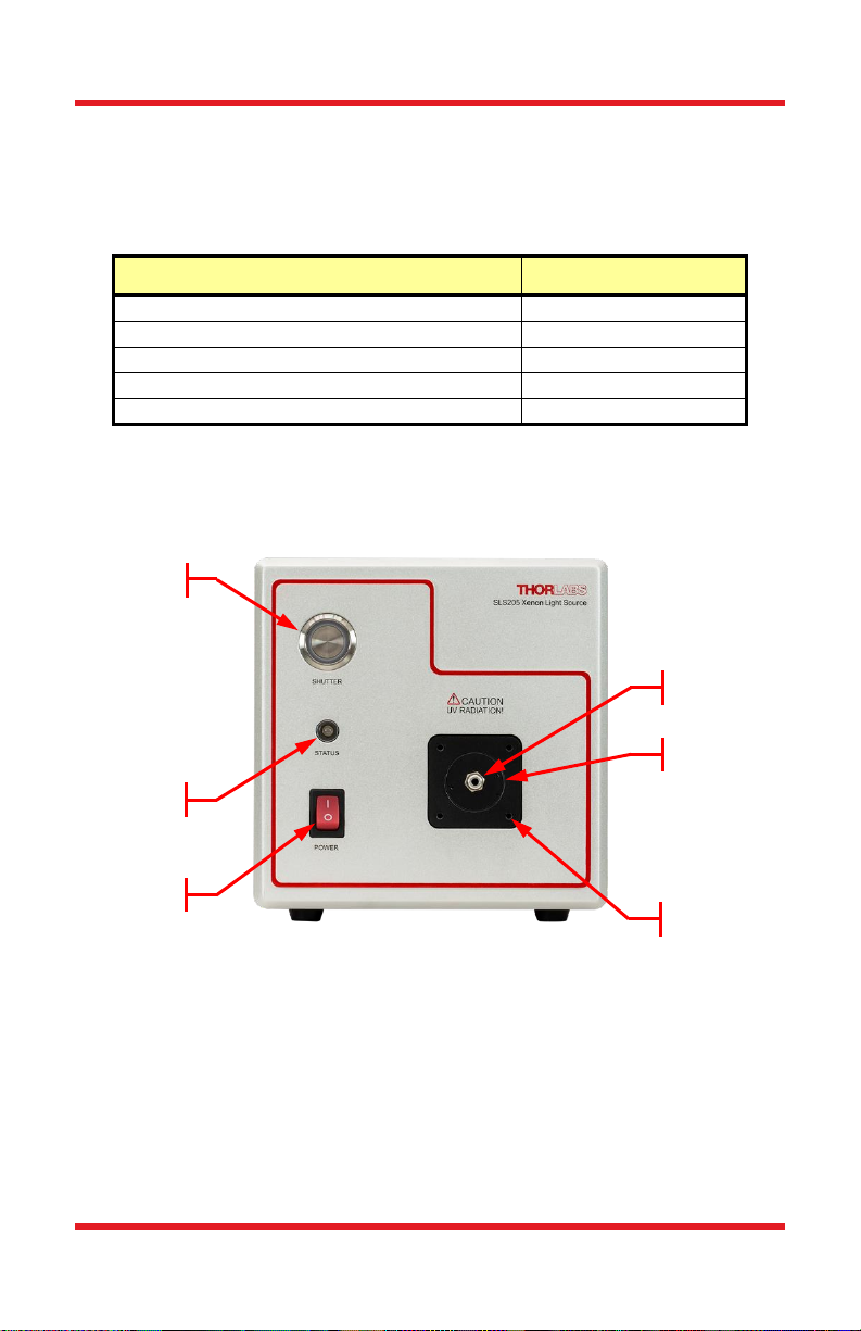
4.2. Operating Elements ....................................................... 6
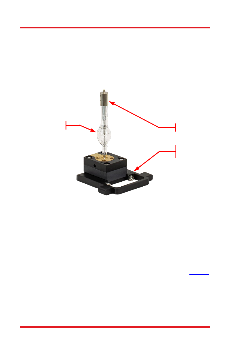
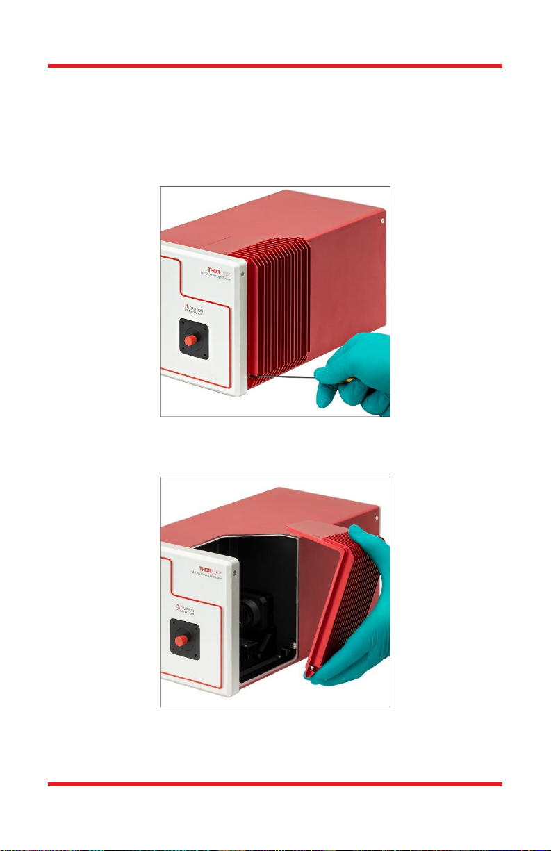
4.3. Bulb Installation ............................................................ 7
4.4. Switching on the Light Source ...................................... 11
4.5. Status Indicator ........................................................... 13
4.6. Application Ideas ......................................................... 13
Chapter 5 Maintenance....................................................................14
5.1. Fuse Replacement........................................................ 14
5.2. Bulb Replacement........................................................ 15
Chapter 6 Specifications.................................................................18
Chapter 7 Mechanical Drawing.......................................................19
Chapter 8 Certifications and Compliances ...................................20
Chapter 9 Regulatory.......................................................................22
Chapter 10 Thorlabs Worldwide Contacts.......................................23

75 W Xenon Light Source Chapter 1: Warning Symbol Definitions
Rev C, September 9, 2020 Page 1
Chapter 1 Warning Symbol Definitions
Below is a list of warning symbols you may encounter in this manual or on your
device.
Symbol
Description
Direct Current
Alternating Current
Both Direct and Alternating Current
Earth Ground Terminal
Protective Conductor Terminal
Frame or Chassis Terminal
Equipotentiality
On (Supply)
Off (Supply)
In Position of a Bi-Stable Push Control
Out Position of a Bi-Stable Push Control
Caution: Risk of Electric Shock
Caution: Hot Surface
Caution: Risk of Danger
Warning: Laser Radiation
Caution: ESD Sensitive Components

75 W Xenon Light Source Chapter 2: Safety
Page 2 CTN014628-D02
Chapter 2 Safety
The lamp comes with a switching power supply compatible with voltages from 100
to 240 VAC. There is no need to change the fuse.
WARNING
Do not operate this device in explosive environments.
WARNING
Do not operate this device in wet or damp conditions.
WARNING
Do NOT look directly at the light source beam during operation. Do NOT place
hand or body part in the light beam as this may cause burning.
CAUTION: HOT SURFACE
The housing of the lamp can get very hot during operation.
Extensive contact may cause burning
WARNING: HOT SURFACE
The temperature of the bulb may reach a few hundred ˚C during operation.
Always wait for at least 30 minutes for the bulb module to cool down before
performing a bulb module replacement. Always wear gloves when handling bulb
modules.

75 W Xenon Light Source Chapter 2: Safety
Rev C, September 9, 2020 Page 3
WARNING: SHOCK
High voltage inside. To avoid electrical shock, before powering unit, make sure
that the protective conductor of the 3-conductor power cord is correctly
connected to the protective earth contact of the socket outlet. Improper
grounding can cause electric shock resulting in severe injury or even death.
Do not operate without cover installed.

75 W Xenon Light Source Chapter 3: Product Overview
Page 4 CTN014628-D02
Chapter 3 Product Overview
3.1. Xenon Light Source
An arc lamp is a light source that generates light from gas discharge. The
construction of a double ended arc lamp bulb is shown in Figure 1 mounted to the
handle. The bulb consists of two metal electrodes sealed in a quartz envelope that
is filled with inert gas.
Figure 1 Structure of the Xenon Lamp Bulb Module
During ignition, high-voltage pulses are sent through the electrodes to ionize the
gas in between, causing arc discharge to occur. After the arc discharge has been
initiated, only a low voltage is required to maintain it. During arc discharge, a
pinpoint-sized cloud of plasma in the arc will generate light with very high
brightness.
3.2. Spectrum
The SLS205 Xenon Light Source provides continuous emission over the 240 to
1200 nm spectral region with intense lines between 800 and 1000 nm. Figure 2
shows the typical output spectrum of the SLS205.
Anode
Base with
Handle
Quartz Envelope

75 W Xenon Light Source Chapter 3: Product Overview
Rev C, September 9, 2020 Page 5
Figure 2 Typical Spectrum
3.3. Optical Configuration
The bulb is placed inside the housing, at the back focus of the first lens. This lens
collimates the output light from the bulb. Then, a second lens focuses the
collimated beam into a multimode fiber patch cable. The rear mirror helps to
increase the coupling efficiency, providing a fiber coupled broadband light source.
The SLS205 light source includes a M111L01 fiber patch cable.
Figure 3 SLS205 Internal Optics

75 W Xenon Light Source Chapter 4: Operation
Page 6 CTN014628-D02
Chapter 4 Operation
4.1. Parts List
The package contains the items listed in the table below.
Name
Quantity
SLS205 Light Source
1
SLS255B Bulb Module
1
M111L01 Fiber Patch Cable
1
2 mm (5/64") Hex Key
1
Location-Specific Power Cord
1
4.2. Operating Elements
Figure 4 Front Panel
Shutter
Switch with
LED
Shutter Switch
with LED
Removable
SMA905
Fiber Adapter
LED Status
Indicator
LED Status
Indicator
SM1 Threading

75 W Xenon Light Source Chapter 4: Operation
Rev C, September 9, 2020 Page 7
Figure 5 Back Panel
4.3. Bulb Installation
WARNING
Always power off the unit and disconnect the power cord before installing the
bulb.
WARNING
Always wear protective gloves when handling the bulb. Moisture and grease
from hands left on the bulb may affect the integrity of the bulb envelope,
shortening the bulb lifetime. At worst, it could cause the bulb to burst.
WARNING
Always use both hands to open the box that stores the bulb. Always handle the
bulb with extreme care when remove its shipping restraints. Always hold the
bulb module by its base. Never hold the bulb by its envelop or electrodes. The
bulb envelop is extremely fragile and mishandling will cause the bulb to crack
or even burst.
AC Power Outlet
Fuse
Label
BNC Port for Bulb
Power Monitor
BNC Port For
External CMOS
Shutter Control
Ventilation
Hole

75 W Xenon Light Source Chapter 4: Operation
Page 8 CTN014628-D02
The bulb module must be installed before operation. Please follow the steps listed
in this section.
1. Make sure the light source is powered off and the power cord is
disconnected.
2. Use the included 5/64" (2 mm) hex key to loosen the 2 panel screws on
the side of the light source.
Figure 6 Loosen the Two Panel Screws
3. Grip the bulb cover and pull to remove it from the housing.
Figure 7 Remove the Bulb Cover
4. Carefully take out the bulb module from its original package. While
handling the bulb module, hold it only by its base.

75 W Xenon Light Source Chapter 4: Operation
Rev C, September 9, 2020 Page 9
Figure 8 Take out the Bulb from Packaging
5. Loosen the four cap screws that hold the shipping restraints to the bulb
base with included 2.5 mm hex key. Carefully remove the two shipping
restraints.
Figure 9 Loose the four cap screws and remove the shipping restraints
6. After removing the shipping restraints, carefully remove the silicone
cushion on the anode of the bulb.
Shipping
Restraints

75 W Xenon Light Source Chapter 4: Operation
Page 10 CTN014628-D02
Figure 10 Silicone Cushion on Bulb Anode
7. Carefully slide in the bulb module into the optics base. Always hold the
module by the base. Do not hold the bulb by the glass envelope.
Figure 11 Install the Bulb

75 W Xenon Light Source Chapter 4: Operation
Rev C, September 9, 2020 Page 11
8. Mount the heat sink on the anode and ensure it is securely in place,
then tighten the thumbscrew by turning it clockwise by hand.
Figure 12 Mount the Heat Sink and Tighten the Thumbscrew
9. Slide in the bulb cover back onto the housing and tighten the panel
screws. Please keep the original bulb module package for future
storage of a used bulb.
4.4. Switching on the Light Source
CAUTION: HOT SURFACE
The housing of the light source can get very hot during operation. The
temperature may reach ~60 °C.
Avoid extensive contact with skin.
WARNING
The light source generates UV output. Do NOT look directly at the light source
beam during operation. Do NOT place hand or body part in the light beam as
this may cause burning.
After setting up the light source on a work surface, follow the steps below to switch
it on.

75 W Xenon Light Source Chapter 4: Operation
Page 12 CTN014628-D02
1. Ensure the rocker switch is in the “O” position. Then, connect the power
cord.
2. Connect one SMA connector of the included fiber patch cable to the fiber
adapter on the front panel, and lock the SMA connector.
3. Toggle the rocker switch to the “I” position to light up the lamp. After it is
switched on, the status LED indicator will be on and show GREEN color
if there is no error. For other status indicators, see Section 4.4.
4. Press the SHUTTER button to open the shutter. The LED on the button
will be ON and light up white after the button is pressed.
5. Please allow 45 - 60 minutes for the light source to stabilize and reach a
state of equilibrium.
6. To close the shutter, press the SHUTTER button again; the LED on the
button will go OFF as well.
7. To power off the unit, toggle the rocker switch to “O” position.
Two shutter control modes are available for the SLS205 Xenon Light Source:
manual control using the switch on the front panel and external control using the 0
- 5 V CMOS BNC port on the back panel. The BNC connection can provides up to
10 Hz (burst) shutter control with the high state (3.8 V to 5 V) closing the shutter
and the low state (0 V to 1.5 V) opening the shutter. In order to switch control
modes, the shutter must be closed.
Figure 13 Switching on the SLS205

75 W Xenon Light Source Chapter 4: Operation
Rev C, September 9, 2020 Page 13
4.5. Status Indicator
The LED next to the power switch indicates the status of the light source.
•If the indicator is GREEN, the device is operating under regular conditions
without any error.
•If the indicator is YELLOW, the device is still operational but the bulb is
close to end of life.
•If the indicator is RED, either the device has overheated, the bulb has
failed to ignite, or the bulb has reached the end of life. Please power off
the light source and wait for it to reachroom temperature before powering
on again. If the error remains, contact Thorlabs Tech Support.
Additionally, the bulb power monitor provides a voltage that can be used as a
feedback signal to monitor the brightness of the bulb. This is calibrated to 2.5 V ±
0.1 V in factory for the included bulb module. The brightness of bulb varies from
lot to lot. If the bulb is replaced this voltage could change +/-10%.
4.6. Application Ideas
The SLS205 Xenon Light Source provides compatibility with Thorlabs’ cage
system and standard SM1 (1.035"-40) optomechanics. The fiber adapter on the
front panel is an SMA-SM1 fiber adapter and can be removed with a Thorlabs
SPW909 Spanner Wrench to expose the internal SM1 thread.
With the fiber adapter removed, the light source operates as a free-space source.
Complex optical systems can be built on to the light source utilizing the 30 mm
cage system and SM1 optomechanics, as shown in Figure 7.
Figure 14 SLS205 with 30 mm Cage System and SM1 Lens Tube
It is also possible to replace the SMA-SM1 fiber adapter with other types of SM1
fiber adapter for compatibility with various types of fiber patch cables.

75 W Xenon Light Source Chapter 5: Maintenance
Page 14 CTN014628-D02
Chapter 5 Maintenance
5.1. Fuse Replacement
WARNING
Always power off the unit and disconnect power cord before operating a fuse
replacement.
The fuse is located in the fuse drawer below the power inlet. To replace the fuse,
press the two clips on the drawer and pull it out, as shown in Figure 8.
Figure 15 Fuse Replacement
Take out the used fuses and put in new ones. Please use a 3.15 A, 250 VAC, Type
"T”, slow blow fuse only.

75 W Xenon Light Source Chapter 5: Maintenance
Rev C, September 9, 2020 Page 15
5.2. Bulb Replacement
WARNING
Always power off the unit and disconnect power cord before replacing the bulb.
CAUTION
The bulb surface temperature may reach a few hundred °C during operation.
Always wait at least 30 minutes after turning off the lamp for cool down before
performing a bulb module replacement.
WARNING
Always wear protective gloves when handling the bulb. Moisture and grease
from hands left on the bulb may affect the integrity of the bulb envelope,
shortening the bulb lifetime. At worst, it could cause the bulb to explode.
WARNING
Always use both hands to open the box that storages the bulb. Always handle
the bulb with extreme care when remove its shipping restraints. Always hold the
bulb module on this base. Never hold the bulb on its envelop or eletrodes. The
bulb envelop is extremely fragile and mishandling would cause the bulb to
crack or even burst.
Thorlabs defines the end of life condition of the bulb as a drop in intensity to ≤50%
of the initial output. When the lifetime of the bulb is reached, the LED indicator on
the front panel will turn red. Please follow the steps listed in this section to replace
the bulb.
1. Power off the unit and disconnect the power cord. Wait at least
30 minutes for the unit to cool down.
2. Use the included 5/64" (2 mm) hex key to loosen the 2 panel
screws on the side of the light source.Grip the bulb cover and
slide it sideways to remove it from the housing.

75 W Xenon Light Source Chapter 5: Maintenance
Page 16 CTN014628-D02
Figure 16 Remove the Bulb Cover
3. While holding the anode heat sink, loosen the black thumbscrew
by hand, turning it counter-clockwise. Remove the heat sink and
mount it on the internal side of the front panel.
4. Carefully slide out the old bulb module from the optics base.
Always hold the module at its handle. Avoid holding the glass
envelope.
Figure 17 Remove the Heat Sink and Take Out the Bulb

75 W Xenon Light Source Chapter 5: Maintenance
Rev C, September 9, 2020 Page 17
5. Put the silicone cushion from orginal package on the bulb anode.
Figure 18 Put Silicone Cushion on Bulb Anode
6. Install the shipping restraints. Please note that the two shipping
restraints are NOT identical to each other: the left piece is
slightly shorter in the top arm than the right piece is. Tighten the
four cap screws, locking the shipping restraints to the bulb base.
Figure 19 Install the Shiping Restraints on the Bulb Base
7. Carefully put the bulb back to its original package.
8. Install a new bulb by following the instruction in section 4.3 Bulb
Installation.
Shipping
Restraints

75 W Xenon Light Source Chapter 6: Specifications
Page 18 CTN014628-D02
Chapter 6 Specifications
Name
Quantity
Wavelength Range
240 - 1200 nm (Fiber Coupled)
Bulb Electrical Power
75 W
Output Fiber
M111L01 Patch Cable (Included)
Ø105 μm, 0.22 NA, SMA905 Connectors
Fiber-Coupled Output Power1
5.5 mW (Typical)
Free-Space Output Power2
290 mW (Typical)
Fiber-Coupled Color Temperature1
5400 K (Typical)
Free-Space Color Temperature2
5800 K (Typical)
Output Power Drift
0.12% Per Hour (Typical)
0.1% Per °C (Typical)
Output Power Stability3
<0.5%
Bulb Life Time4
2000 h
Bulb Arc Gap
1.3 mm
Shutter Switch Time
5 ms
Shutter Repetition Rate (Max)
10 Hz (Burst)
Monitor
0 –5 V Analog
External Shutter Control
0 –5 V CMOS
Power Supply
100 - 240 VAC, 50 - 60 Hz
Operating Temperature
0 - 45 °C
Storage Temperature
-15 - 70 °C
Dimension (L x W x H)
325.6 mm x 162.5 mm x 162.8 mm
(12.82" x 6.40" x 6.41")
1
Measured with included fiber patch cable at beginning of bulb lifetime.
2
Measured at the Output Port with the Fiber Adapter Removed at
Beginning of Bulb Lifetime
3
Standard deviation of optical power measured at room temp. over a 1
hour period (after 45 minutes of warm-up) with a 1 Hz sampling rate.
4
Thorlabs defines the end of life condition of this light source as a drop
in intensity to ≤50% of the initial output at 532 nm.
Table of contents
Other THORLABS Lighting Equipment manuals

THORLABS
THORLABS M365L1 User manual

THORLABS
THORLABS SLS203L User manual

THORLABS
THORLABS SLS401 User manual

THORLABS
THORLABS S5FC Series User manual

THORLABS
THORLABS SLS303 User manual

THORLABS
THORLABS HPLS343 User manual

THORLABS
THORLABS OSL2 User manual

THORLABS
THORLABS PSY240E User manual

THORLABS
THORLABS LEDD3 Series User manual

THORLABS
THORLABS CHROLIS User manual