MV0 / MV1 / MV2 QUICK INSTALLATION GUIDE
REER S.p.A. Via Carcano 32, 10153 Torino Italia 8541455 - Rev. 0 - 06/04/2021 1
Tel. +39 0112482215 r.a. Fax +39 011859867
Installazione - Precauzioni particolari
Una installazione meccanica dei sensori di prossimità non adeguata può provocare un funzionamento pericoloso. Prestare particolare attenzione al
dimensionamento della ruota fonica e al fissaggio meccanico dei sensori.
In ogni condizione di velocità prevista il modulo MVxxx deve essere in grado di rilevare la velocità. Durante l’installazione (e poi periodicamente) eseguire un
test completo del sistema. Mediante il software MSD oppure verificando l’accensione dei LED relativi ai sensori accertarsi che il modulo non rilevi in nessun caso
delle anomalie.
Il dimensionamento della ruota fonica, e/o il posizionamento dei sensori e degli encoder, deve essere fatto seguendo i dati tecnici di questi ultimi e le relative
linee guida del costruttore.
Prestare inoltre particolare attenzione a guasti di modo comune (CCF) che possano coinvolgere i sensori (corto circuito di cavi, caduta di oggetti dall’alto,
rotazione folle della ruota fonica, distacco dell’encoder, etc).
Installation - Particular precautions
An inadequate mechanical installation of proximity sensors can cause dangerous operation. Pay particular attention to the size of the phonic wheel and to the
mechanical fixing of the sensors.
In any condition of expected speed, the MVxxx module must be able to detect the speed. During the installation (and then periodically) perform a complete
system test. By using the MSD software or by checking that the LEDs relating to the sensors are lit, make sure that the module does not detect any anomalies
in any case.
The sizing of the exciter, and/or the positioning of the sensors and the encoders, must be done following the technical data of the latter and the manufacturer’s
guidelines.
Pay particular attention to Common Cause Failures (CCF) that may involve the sensors (short circuit of cables, objects falling from above, idle rotation of the
phonic wheel, encoder separation, etc.)
Installation - Précautions particulières
Une installation mécanique incorrecte des capteurs de proximité peut entraîner un fonctionnement dangereux. Portez une attention particulière au
dimensionnement de la roue phonique et à la fixation mécanique des capteurs.
Le module MVxxx doit être capable de détecter la vitesse dans toutes les conditions de vitesse prévues. Effectuez un test complet du système pendant
l'installation (et périodiquement par la suite). Au moyen du logiciel MSD ou en vérifiant que les LED des capteurs s'allument, assurez-vous que le module ne
détecte aucune anomalie.
Le dimensionnement de la roue phonique, et/ou le positionnement des capteurs et des encodeurs, doivent être effectués conformément aux données
techniques des capteurs et aux directives pertinentes du fabricant.
En outre, il faut prêter une attention particulière aux défaillances de mode commun (CCF) qui peuvent affecter les capteurs (court-circuit des câbles, chute
d'objets par le haut, rotation à vide de la roue phonique, détachement de l'encodeur, etc).
Installation - Besondere Vorsichtsmaßnahmen
Eine unsachgemäße mechanische Installation der Näherungssensoren kann zu einer gefährlichen Situation beim Betrieb führen. Achten Sie besonders auf die
Dimensionierung des Impulsrads und die mechanische Befestigung der Sensoren.
Das MVxxx-Modul muss in der Lage sein, die Drehzahl unter allen zu erwartenden Drehzahlbedingungen zu erfassen. Führen Sie während der Installation (und
in regelmäßigen Abständen danach) einen vollständigen Systemtest durch. Stellen Sie mit Hilfe der MSD-Software oder durch Überprüfung des Aufleuchtens
der LEDs an den Sensoren sicher, dass das Modul keine Anomalien erkennt.
Die Dimensionierung des Impulsrads, und/oder die Positionierung der Sensoren und Geber, müssen gemäß den technischen Daten letztere und den
entsprechenden Richtlinien des Herstellers erfolgen.
Achten Sie außerdem besonders auf gemeinsam verursachte Ausfälle (GVA), die Sensoren beinhalten können (Kurzschluss von Kabeln, herabfallende
Gegenstände von oben, Leerlauf des Impulsrads, Gebertrennung, usw).
Instalación - Precauciones especiales
Una instalación mecánica incorrecta de los sensores de proximidad puede provocar un funcionamiento peligroso. Preste especial atención al dimensionamiento
de la rueda fónica y a la fijación mecánica de los sensores.
El módulo MVxxx debe ser capaz de detectar la velocidad en todas las condiciones de velocidad previstas. Realice una prueba completa del sistema durante la
instalación (y periódicamente después). Mediante el software MSD o comprobando que los LEDs de los sensores se encienden, asegúrese de que el módulo no
detecta ninguna anomalía.
El dimensionamiento de la rueda fónica, y/o la colocación de los sensores y codificadores, debe hacerse de acuerdo con los datos técnicos de los sensores y las
directrices pertinentes del fabricante.
Además, preste especial atención a los fallos de modo común (CCF) que pueden afectar sensores (cortocircuito de los cables, caída de objetos desde arriba,
rotación en vacío de la rueda fónica, separación de codificadores, etc.).
A) MONTAGGIO MECCANICO - MECHANICAL ASSEMBLY - MONTAGE MECANIQUE - BEFESTIGUNG - MONTAJE MECÁNICO
Le operazioni che seguono devono essere effettuate in assenza di alimentazione.
Fissare alla barra Omega DIN 35mm (EN 5022) un numero di connettori posteriori “MSC” a 5 poli uguale al numero di moduli da
montare (agganciandoli prima in alto). Collegare fra loro i connettori appena montati. Fissare quindi i moduli alla barra ponendo
attenzione a inserire la contattiera posta sul fondo del modulo sul rispettivo connettore. Premere il modulo delicatamente fino a
sentire lo scatto del bloccaggio. Per rimuovere un modulo è necessario tirare verso il basso (utilizzando un cacciavite) il gancio di
arresto posto sul retro del modulo; sollevare quindi il modulo dal basso e tirare.
Do not apply power supply before carry out the following operations.
Fix to the Omega DIN 35mm (EN 5022) the same number of "MSC" 5-pole rear panel connectors as the number of units to be
installed (hooking them at the top first). Connect between them the connectors just mounted. Fasten the units to the rail,
arranging the contacts on the base of the unit on the respective connector. Press the unit gently until you feel it snap into place.
To remove a unit, use a screwdriver to pull down the locking latch on the back of the unit; then lift the unit upwards and pull.
Les opérations suivantes doivent être effectuées en l'absence d'alimentation.
Fixer à la barre oméga DIN 35mm (EN 5022) un nombre de connecteurs arrière "MSC" à 5 pôles égal au nombre de modules à
monter (en les accrochant d'abord en haut). Connectez ensemble les connecteurs nouvellement montés. Fixer ensuite les
modules à la barre en faisant attention d’introduire le contact situé sur le fond du module dans le connecteur correspondant.
Appuyer délicatement sur le module jusqu’à entendre le déclic de blocage. Pour enlever un module, il faut tirer vers le bas (à l’aide
d’un tournevis) le crochet d’arrêt situé à l’arrière du module; puis soulever le module par le bas et tirer.
Die im Anschluss beschriebenen Vorgänge müssen bei unterbrochener Stromversorgung ausgeführt werden.
Befestigen Sie an der DIN 35mm-Omega-Schiene (EN 5022) eine der Anzahl der zu montierenden Module entsprechende Anzahl
von 5-poliger "MSC"-Rücksteckern (zuerst oben einhängen). Verbinden Sie die neu montierten Stecker miteinander. Dann die
Module an der Schiene befestigen und dabei darauf achten, die Kontaktvorrichtung auf dem Boden des Moduls auf den
entsprechenden Verbinder zu setzen. Das Modul vorsichtig einsetzen, bis das Einrasten zu hören ist. Um das Modul zu entfernen,
muss (unter Verwendung eines Schraubenziehers) der Sperrhaken auf der Rückseite des Moduls nach unten gezogen und dann
das Modul von unten angehoben und nach oben gezogen werden.
Las siguientes operaciones se deben llevar a cabo con la alimentación cortada.
Fije a la barra Omega DIN 35mm (EN 5022) un número de conectores traseros "MSC" de 5 polos igual al número de módulos a
montar (enganchándolos primero en la parte superior). Conecte los conectores recién montados. Luego, fijar los módulos en la
barra comprobando la introducción del elemento de contacto, presente en la parte inferior del módulo, en el conector
correspondiente. Ejercer una delicada presión sobre el módulo hasta sentir el chasquido de bloqueo. Para retirar un módulo es
necesario tirar hacia abajo (utilizando un destornillador) el gancho de fijación presente en la parte trasera del mismo; luego, alzar
el módulo desde abajo y tirar.
B) SEGNALAZIONI - STATUS INDICATORS - INDICATEURS - STATUSANZEIGEN - INDICADORES DE ESTADO
OFF
if the unit is waiting
for the first
communication
from the MASTER
FLASHES
if no INPUT or
OUTPUT requested
by the
configuration
ON
if INPUT or OUTPUT
requested by the
configuration
Shows the
NODE_SEL0/1
signal table
ON
Encoder
connected
and
operative
ON
Proximity
connected
and
operative
OFF
Axis in
normal
speed range
BLINKING
Axis in
overspeed
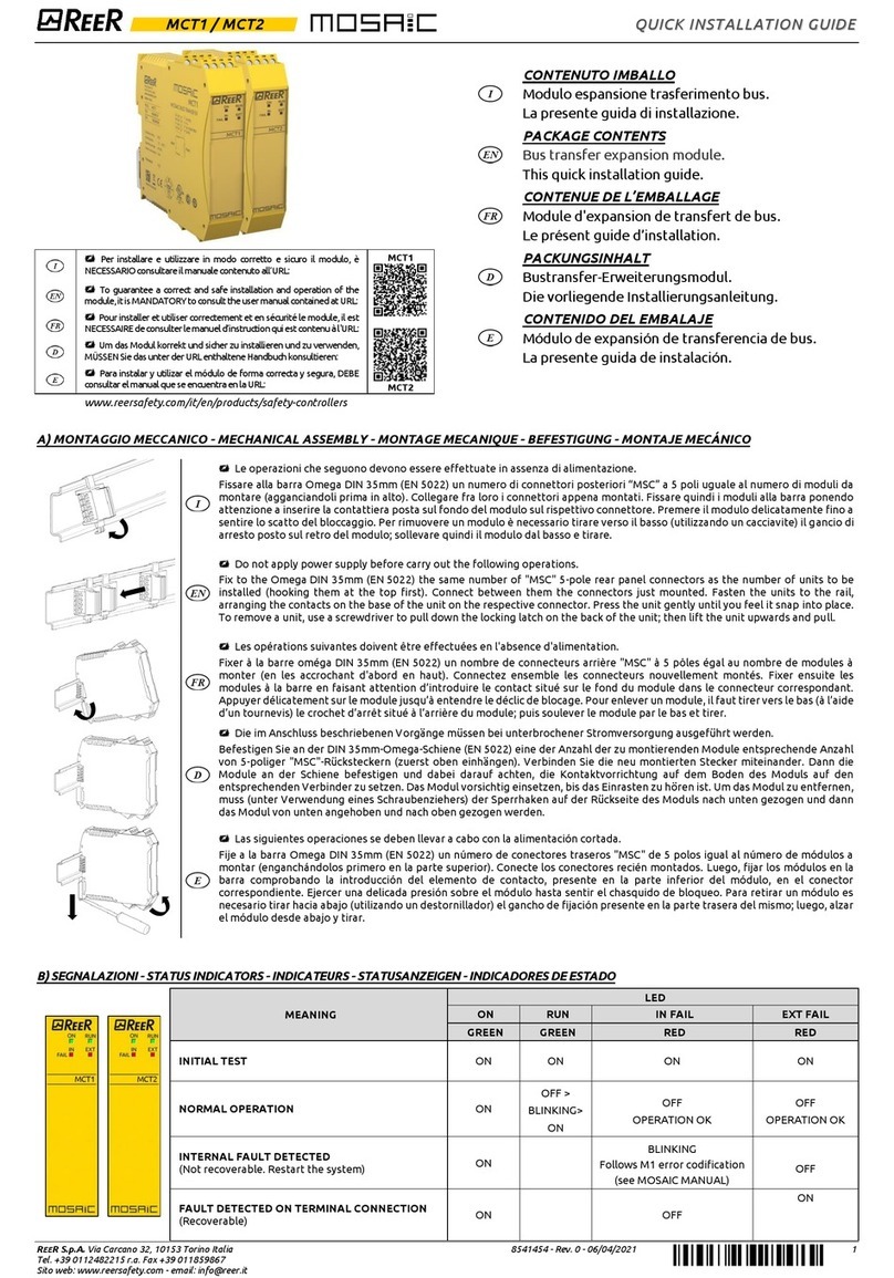
CONTENUTO IMBALLO
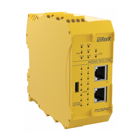
Moduli di sicurezza per il controllo di velocità.
La presente guida di installazione.
PACKAGE CONTENTS
Safety speed monitoring modules.
This quick installation guide.
CONTENUE DE L’EMBALLAGE
Modules de sécurité pour le contrôle de la vitesse.
Le présent guide d’installation.
PACKUNGSINHALT
Sicherheitsmodule zur Geschwindigkeitsüberwachung.
Die vorliegende Installierungsanleitung.
CONTENIDO DEL EMBALAJE
Módulos de seguridad para el control de la velocidad.
La presente guida de instalación.
Per installare e utilizzare in modo corretto e sicuro il modulo, è
NECESSARIO consultare il manuale contenuto all’URL:
To guarantee a correct and safe installation and operation of the
module,it is MANDATORY to consult the user manual contained at URL:
Pour installer et utiliser correctement et en sécurité le module, il est
NECESSAIREdeconsulterlemanueld’instruction qui est contenu à l'URL:
Um das Modul korrekt und sicher zu installieren und zu verwenden,
MÜSSENSie das unter der URL enthaltene Handbuch konsultieren:
Para instalar y utilizar el módulo de forma correcta y segura, DEBE
consultar elmanual que se encuentra en la URL:
www.reersafety.com/it/en/products/safety-controllers
